
Related Manuals for Bertazzoni HER366BCFEPAVT


Summary of Contents for Bertazzoni HER366BCFEPAVT
- Page 1 INSTALLATION MANUAL USER AND MAINTENANCE MANUAL FREESTANDING DUAL FUEL RANGES, GAS WORKTOP, ELECTRIC SELF CLEAN OVEN MODEL www.bertazzoni.com...
- Page 3 Bertazzoni becomes a real pleasure. This manual will help you learn to use and care for your Bertazzoni appliance in the safest and most effective way, so that it can give you the highest satisfaction for years to come.
- Page 5 USER MANUAL VALIDITY The following manual is valid for all the product codes mentioned below: • MAS366BCFEPXT • PRO366BCFEPGIT • PRO366BCFEPNET • PRO366BCFEPROT • PRO366BCFEPART • PRO366BCFEPBIT • PRO366BCFEPXT • HER366BCFEPAVT • HER366BCFEPNET • HER366BCFEPXT...
-
Page 6: Table Of Contents
............... . . BERTAZZONI SERVICE . - Page 7 ..............KEEPING YOUR BERTAZZONI CLEAN .
-
Page 9: Installation Manual
WHAT TO DO IF YOU SMELL GAS Natural or LP gas. • Do not try to light any appliance. FOR THE INSTALLER: Before installing the Bertazzoni • Do not touch any electrical switch. appliance, please read these instructions carefully. This appliance shall be installed in accordance with the •... -
Page 10: Data Rating Label
WARNINGS WARNING Cancer and Reproductive Harm — www. P65Warnings.ca.gov. DATA RATING LABEL The data rating label shows the model and serial number of the range. It is located under the control panel and in the last page of this manual. Fig. -
Page 11: Before Installation
BEFORE INSTALLATION • This appliance shall only be installed by an authorized A manual valve shall be installed in an accessible location professional. in the gas line external to the appliance for the purpose of turning on or shutting off gas to the appliance. •... -
Page 12: Ventilation Preparation
VENTILATION PREPARATION This range will best perform when installed with Bertazzoni exhaust hoods. These hoods have been designed to work in conjunction with the Bertazzoni range and have the same finish for a perfect look. Before installation of the exhaust hood, consult local or regional building and installation codes for additional specific clearance requirements. -
Page 13: Specifications
SPECIFICATIONS 25'' 15/16 3 '' 7/16 11/16 Fig. 2 • A 36″ • B 37″½ MAX INJEC- PRES- BURNER MAX RATE MIN RATE BY–PASS SURE diam.[mm] Type [iwc] [Btu/hr] [Btu/hr] diam.[mm] 3,500 0.90 4″ 1,025 Regulated Auxiliary 3,300 0.54 10″ 0.29 (Propane) 5,900... -
Page 14: Clearance Dimensions
CLEARANCE DIMENSIONS INSTALLATION ADJACENT TO KITCHEN METAL HOOD CABINETS 36″(91.5 cm) This range may be installed directly adjacent to existing 25 1/2″(65 cm) and 31 1/2″ (80 cm) countertop high cabinets (36″ or 91.5 cm from the floor). 13″ (33.0 cm) For the best look, the worktop should be level with the 18″... -
Page 15: Installation Requirements
INSTALLATION REQUIREMENTS Fig. 5 Fig. 6 installation area for the connection ELECTRICAL A properly-grounded horizontally- mounted electrical receptacle should be installed no higher than 3″ (7.6 cm) above the floor, no less than 2″ (5 cm) and no more than 8″ (20.3 cm) from the left side (facing product). -
Page 16: Electrical Connection
ELECTRICAL CONNECTION ELECTRICAL GROUNDING WARNING ELECTRICAL SHOCK HAZARD This appliance is equipped with a three-prong plug for your protection against shock hazard and should be plugged Disconnect electrical power at the directly into a properly grounded socket. Do not cut or circuit breaker box or fuse box before remove the grounding prong from this plug. -
Page 17: Four Wires Connection
ELECTRICAL CONNECTION FOUR WIRES CONNECTION • Connect the L1 receptacle terminal to the incoming BLACK electrical supply wire (L1-hot wire) • Connect the L2 receptacle terminal to the incoming RED electrical supply wire (L2-hot wire) • Connect the NEUTRAL receptacle terminal to the incoming NEUTRAL (WHITE) electrical supply wire •... -
Page 18: Wiring Diagram
WIRING DIAGRAM The electric wiring diagrams and schematics are attached behind the range, and should not be removed except by a service technician, then replaced after service. Fig. 11... -
Page 19: Gas Connection
GAS CONNECTION FLEXIBLE CONNECTIONS WARNING DO NOT USE AN OPEN FLAME WHEN In case of installation with flexible couplings and/ or quick- CHECKING FOR LEAKS! disconnect fittings, the installer must use a heavy-duty, AGA design-certified commercial flexible connector of at Leak testing of the appliance shall be conducted according least 1/2″... -
Page 20: Pressure Regulator
GAS CONNECTION PRESSURE REGULATOR Since service pressure may fluctuate with local demand, every gas cooking appliance must be equipped with a pressure regulator on the incoming service line for safe and efficient operation. The pressure regulator shipped with the appliance has two female threads 1/2″... -
Page 21: Installation
INSTALLATION APPLIANCE INSTALLATION REMOVING THE OVEN DOOR UNPACKING THE RANGE Prepare the door for removal. Flip up the locking clamps on each door hinge. Slowly shut the door until the protruding • Remove all packing materials from the shipping pallet clamps stop the movement. -
Page 22: Installing The Legs
INSTALLATION INSTALLING THE LEGS INSTALLING THE WORKTOP FRONTGUARD Bertazzoni ranges must be used only with the legs properly To increase the clearance between the front edge of the installed. worktop and the burners, it is possible to install a front guard for the worktop. -
Page 23: Installing The Island Trim
INSTALLATION INSTALLING THE ISLAND TRIM INSTALLING BACKGUARD (OPTIONAL) The island trim must be installed prior to operation of the The backguard must be installed prior to operation of the appliance appropriate ventilation oven appliance appropriate ventilation oven compartment. compartment. The island trim is only placed on the cooktop, remove all The backguard is an optional contact you dealer for buying tape and packaging before installing it. -
Page 24: Installing The Anti/Tip Devices
INSTALLING THE ANTI/TIP DEVICES ANTI-TIP BRACKETS ANTI/TILT CHAIN The anti-tip bracket shipped with the range must be The anti-tilt chain shall be installed on right or left side properly secured to the rear wall as shown in the picture alternatively according below instructions. The chain shall below. - Page 25 INSTALLING THE ANTI/TIP DEVICES Fig. 24 • A CLOSED RING • B OPEN HOOK...
-
Page 26: Gas Conversion
GAS CONVERSION STEP 1: PRESSURE REGULATOR WARNING Before carrying this operation, The pressure regulator supplied with the appliance is a disconnect the appliance from gas and convertible type pressure regulator for use with Natural electricity. Gas at a nominal outlet pressure of 4″ iwc or LP gas at a nominal outlet pressure of 10″... -
Page 27: Step 2: Surface Burners
Replace nozzles using the conversion set supplied with the and will disappear with use. With propane (LP) gas, slight range or by a Bertazzoni authorized parts warehouse. Each yellow tips on the primary icon are normal. nozzle has a number indicating its flow diameter printed on the body. -
Page 28: Step 4: Minimum Flame Adjustment
GAS CONVERSION STEP 4: MINIMUM FLAME ADJUSTMENT SURFACE BURNERS WARNING Light one burner at a time and set the knob to the MINIMUM position (small flame). These adjustments should be made only for use of the appliance with natural gas. Remove the knob. -
Page 29: Installation Checklist
INSTALLATION CHECKLIST A qualified installer should carry out the following checks: Range mounted on its legs Island trim or Backguard attached according to instruction Anti-tip device properly installed Clearance to cabinet surfaces as manufacturer’s guideline Proper ground connection Gas service line connected following manufacturer’s guideline Valves, stoppers and gasket installed between the range and the service line... -
Page 30: Final Preparation
FINAL PREPARATION • Before using the appliance, remove any protective wrap from the stainless steel. • All stainless steel body parts should be wiped with hot, soapy water and with a liquid stainless steel cleanser. • If buildup occurs, do not use steel wool, abrasive cloths, cleaners, or powders! •... -
Page 31: Bertazzoni Service
Bertazzoni is committed to providing the best customer and product service. We have a dedicated team of trained professionals to answer your needs. If you own a Bertazzoni appliance and need service in the US or Canada please use the following contact information: If located in the USA: 866 905 0010 https://us.bertazzoni.com/more/support... -
Page 32: User And Maintenance Manual
WARNINGS TO PREVENT FIRE OR SMOKE DAMAGE Warning and Important Safety Instructions appearing in this manual are not meant to cover all possible conditions and • Be sure all packing materials are removed from the situations that may occur. Common sense, caution, and appliance before operating it. -
Page 33: Cooking Safety
WARNINGS COOKING SAFETY • DO NOT cook directly on the oven bottom. This could result in damage to your appliance. Always use the oven racks when cooking in the oven. • Once the unit has been installed as outlined in the Installation Instructions, it is important that the fresh air Do not connect any appliances to the plugs above or near supply is not obstructed. -
Page 34: Induction Cooking Surfaces
WARNINGS INDUCTION COOKING SURFACES OVEN HEATING ELEMENTS • Surface areas on or adjacent to the unit may be hot • NEVER touch oven bake and broil burner areas or enough to cause burns. Do not touch the cooking area interior surfaces of oven. as long as the light indicating residual heat on the glass- •... -
Page 35: Electrical Shock Hazard
WARNINGS ELECTRICAL SHOCK HAZARD WARNING-TIPPING HAZARD Make sure all controls are OFF and oven is COOL before Children and adults can tip over the range if it has not been cleaning. Failure to do so can result in burns or electrical secured. -
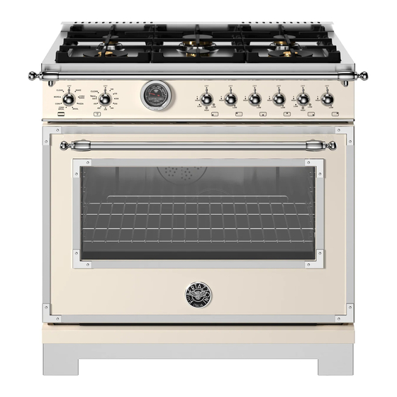
Page 36: Worktop And Knobs Layout
WORKTOP AND KNOBS LAYOUT Fig. 31 HEATING ELEMENT Oven functions selector Oven thermostat Left front burner Left rear burner Central front burner Central rear burner Right front burner Right rear burner... -
Page 37: Gas Cooktop
GAS COOKTOP BURNER CAPS AND GRATES MAKING SURE THE FLAME IS OPTIMAL The burners and the burner caps must be properly placed The flame should be stable with no excessive noise or for the cooktop to function properly. fluttering. The color should be blue with no yellow on the tips. -
Page 38: Using The Gas Burners
GAS COOKTOP USING THE GAS BURNERS USING THE POWER BURNERS • Press in the control knob and turn it anti-clockwise, to To give further flexibility, the dual power burner can be used HIGH position. as a single simmer burner if the central burner alone is ignited or as a power burner if the outer burner is also •... -
Page 39: Using Specialty Cookware
GAS COOKTOP USING SPECIALTY COOKWARE SIMMER RING For very slow cooking the porcelain coated simmer ring WOKS should be used. In some models the porcelain- coated cast Either flat-based or round-bottom woks with the accessory iron simmer ring must be purchased separately. Simmer ring can be used on all models. -
Page 40: Electric Oven
ELECTRIC OVEN OVEN COOKING MODES CAUTION When using the oven for the first time it The oven is equipped with 4 heating elements, used alone should be operated for 15-30 minutes at a or in combination to create different cooking modes: temperature of about 500℉/260℃... -
Page 41: Special Functions/More
ELECTRIC OVEN SPECIAL FUNCTIONS/MORE BROIL Heat from the broil element only. DEHYDRATE The BROIL setting creates intense heat from the top of the Heat from lower element and air flow convection with fan. cavity. The broil mode is effective when food is placed on upper racks. -
Page 42: Condensation
ELECTRIC OVEN CONDENSATION GETTING THE BEST RESULTS • Minimize opening and closing the oven door during It is normal for a certain amount of moisture to evaporate operation. from the food during any cooking process. The amount depends on the moisture content of the food. The moisture •... -
Page 43: Broiling Recommendation
ELECTRIC OVEN BROILING RECOMMENDATION FOOD ITEM CONTROL APPROXIMATE COOKING SPECIAL INSTRUCTIONS TEMPERATURE SETTING TIME AND TIPS SELECTOR BEEF 500℉ fixed temperature 15 to 20 minutes Broil until no pink in center setting Ground Beef Patties, ½″ thick T-Bone Steak 500℉ fixed temperature 12 to 20 minutes Time depends on rareness setting... -
Page 44: Air Fry Recommendations
ELECTRIC OVEN AIR FRY RECOMMENDATIONS ITEM AMOUNT TEMPERATURE TIME Potatoes Frozen French Fries Frozen 30-35 oz 420℉–440℉ 15-25 min French Fries, Seasoned 25-30 oz 420℉–440℉ 20-25 min Frozen Tater Tots 40–45 oz 400℉–430℉ 20-25 min Frozen Hash Browns 25–30 oz 420℉–440℉... -
Page 45: Oven Temperature Indicator
ELECTRIC OVEN OVEN TEMPERATURE INDICATOR SET THE GAUGE 1) Press MODE. The range is equipped with a device to indicate the temperature in the middle of the oven. This lets you check 2) Use the “<” and “>” buttons to select SET-UP. the temperature inside the oven and adjust food cooking 3) Press MODE. - Page 46 ELECTRIC OVEN TIMER MEAT PROBE 1) Press MODE. The meat probe allows you more control over how your foods are cooked by automatically disabling the specified 2) Use the “<” and “>” buttons to select TIMER. cooking mode when a dish's desired temperature, defined 3) Press MODE.
-
Page 47: Self-Cleaning
ELECTRIC OVEN SELF-CLEANING BEFORE SELF CLEANING THE OVEN WARNING Wipe out large spillages, grease and any loose soil that can be easily removed. Remove any soil that is outside the Children should not be left alone or door seal area. This appliance is designed to clean the unattended in an area where appliances oven interior and the portion of the door that faces the oven are in use. - Page 48 ELECTRIC OVEN AT THE END OF THE SELF-CLEAN CYCLE The self-cleaning cycle lasts approximately 2-2 ¼ hours; 30-40 minutes for pre-heating the oven (pre-heating and clean light both on), 60 minutes for actual cleaning (heating and clean light both on), 30-35 minutes for cool-down (only clean light on).
-
Page 49: Telescopic Glides
ELECTRIC OVEN TELESCOPIC GLIDES REMOVING THE GLIDES 1) Locate the two spring clips at the front and back of the The telescopic glides fit any shelf level and work with the glide. wire shelves provided as standard equipment. 2) Gently pull down the front spring clip. FITTING THE GLIDES 3) Pull the glide away from the oven side - be careful not to 1) Locate the two spring clips at the front and back of the... - Page 50 ELECTRIC OVEN Fig. 43...
-
Page 51: Keeping Your Bertazzoni Clean
KEEPING YOUR BERTAZZONI CLEAN BURN HAZARD CLEANING THE BROILER PAN Make sure the heating elements are turned off and allowed Clean with detergent and hot water. For stubborn spots, to cool completely before any cleaning and/or maintenance use a soap-filled steel wool pad. -
Page 52: Simple Maintenance
866 905 0010 DO NOT touch bulb with bare hands. Clean off any signs of oil from the bulb and handle https://us.bertazzoni.com/more/support with a soft cloth. If located in CANADA 800 561 7265... - Page 53 SIMPLE MAINTENANCE SIDE OVEN LIGHT TOP OVEN LIGHT Bulb type: halogen G9 120 V, 40 W Bulb type: halogen G9 120 V, 40 W • Make sure the heating elements are turned off and • Make sure the heating elements are turned off and allowed to cool completely.
-
Page 54: Troubleshooting
GRILLING IN THE OVEN IS SLOW Here are answer to common problems you may experience. You are also welcome to call our toll free Customer Service line to troubleshoot any issue with your Bertazzoni: Have you selected the correct function? CONDENSATION FORMS IN THE OVEN... -
Page 55: Customer Care
CUSTOMER CARE For any warranty information and service request, contact us: In USA: https://us.bertazzoni.com/more/support In CANADA: https://ca.bertazzoni.com/more/support... - Page 56 Via Palazzina, 8, 42016 Guastalla RE © 2024 BERTAZZONI. All rights reserved. 3100838_v.08...
Need help?
Do you have a question about the HER366BCFEPAVT and is the answer not in the manual?
Questions and answers