
Related Manuals for Heatrae Sadia PremierPlus PP100E


Summary of Contents for Heatrae Sadia PremierPlus PP100E
- Page 1 7032982 Issue 09 PremierPlus Unvented Hot Water Cylinder Installation and User Manual...
-
Page 3: Table Of Contents
IMPORTANT Please read & understand all these instructions before commencing installation. Please leave this manual with the Customer for future reference. page 1 Contents 1. Introduction 1.1 General 1.2 Symbols used 1.3 Abbreviations 1.4 Liabilities 2. Safety 2.1 General safety warnings 2.2 Recommendations 2.3 Specific safety instructions 3. -
Page 4: Introduction
12.1 Spare parts list Benchmark checklist Commissioning & service records Warranty THE BENCHMARK SCHEME Benchmark places responsibilities on both manufacturers and Installers. The purpose is to ensure that Customers are provided with the correct equipment for their needs, that it is installed, commissioned and serviced in accordance with the manufacturer's instructions by competent persons and that it meets the requirements of the appropriate Building Regulations and relevant electrical qualifications. -
Page 5: Abbreviations
Signals important information. 1.3 Abbreviations # T&P - Temperature & Pressure relief valve # PRV - Pressure Reducing Valve # Prv - Pressure relief valve 1.4 Liabilities Manufacturers liability Our products are manufactured in compliance with the requirements of the various applicable European Directives. -
Page 6: Safety
# Water may drip from the discharge pipe of the pressure-relief device and this pipe must be left open to the atmosphere; (see here for more details) # The pressure-relief device is to be operated regularly to remove lime deposits and to verify that it is not blocked;... -
Page 7: Technical Specifications
Do not tamper with any of the safety valves fitted to the system. If a fault is suspected contact a competent Installer. DO NOT bypass the thermal cut-out(s) in any circumstances. Where the inlet supply to the Pressure Reducing Valve (PRV) is routed through a heated space and is fitted with a check valve or other fitting that would prevent backflow, high pressures can be experienced in the inlet pipe due to warming that can cause damage to the PRV or other fittings on the inlet supply. - Page 8 Notes: 1. Indirect cylinders tested in accordance with BS EN 12897:2016. 2. Heat up time from cold through 45°C, based on a flow temperature of 80°C +/- 2°C & normal volume. 3. Although the primary coil pressure rating is 1.0MPa (10bar) the 2 port zone valve and coil compression nuts supplied with the cylinder is only rated 0.86MPa (8.6 bar).
- Page 9 The water heating energy efficiency class of the model The water heating energy 36.2 36.0 37.3 37.1 38.1 37.7 37.7 37.6 37.6 efficiency in The annual electricity 1418 1424 2741 2759 4395 4443 4443 4456 4556 consumption in kWh Daily fuel consumption 6.640 6.680...
-
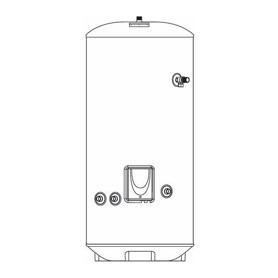
Page 10: Dimensions And Connections
Standing loss 46.3 51.7 60.4 64.2 78.6 86.3 86.3 98.3 98.3 in W Table: Technical parameters in accordance with European Commission regulations 814/2013 and 812/2013 page 6 3.2 Dimensions and connections Figure 1: General dimensions - Direct Item 100E 120E 150E 170E 210E 250E 300E 925 1184 1437 1751 906 1090 1216 1474 1726 2040 Table 3: General dimensions table - Direct... - Page 11 NOTES: Control terminal numbering may differ from those shown. Refer to instructions with controls selected. A double pole isolating switch must be installed in the mains supply. All earth connections must be connected back to the mains earth supply. Figure 2: Schematic wiring diagram - basic 2 x 2 port valve system...
- Page 12 NOTES: Control terminal numbering may differ from those shown. Refer to instructions with controls selected. A double pole isolating switch must be installed in the mains supply. All earth connections must be connected back to the mains earth supply. Figure 3: Schematic wiring diagram - 3 port mid position system page 8 Control Housing Details...
- Page 13 Figure 4: Indirect wiring schematic...
-
Page 14: Description Of The Product
Figure 5: Direct wiring schematic page 9 4. Description of the product 4.1 General description This product is a purpose designed unvented water heater. The unit has a stainless steel inner vessel, which ensures an excellent standard of corrosion resistance. The outer casing is a combination of resilient thermoplastic mouldings and pre-coated steel. -
Page 15: Before Installation
# Cylinder # Factory fitted immersion heater(s) and thermal controls # Factory fitted Temperature and Pressure Relief Valve (set at 90°C / 1 Mpa (10bar)) # Factory fitted indirect thermostat and thermal cut-out # Literature pack Instructions (inc benchmark commissioning checklist & service record) # Cold water control pack Combination valve (inc pressure reducing valve, pressure relief valve and check valve) -
Page 16: Choice Of Location
# It is advantageous in many mixer showers to have a balanced hot and cold water supply, in these instances a balanced cold water connection is available on the combination inlet valve. page 10 Limitations The cylinder should not be used in association with any of the following: # Solid fuel boilers or any other boiler in which the energy input is not under effective thermostatic control, unless additional and appropriate safety measures are installed. -
Page 17: Water Connections
Figure 6: Access schematic (not to scale) page 11 NOTE: A backflow prevention Device may include check valves, a water meter or an additional PRV Figure 7: Typical installation schematic (not to scale) 6.2 Water connections WARNING Under no circumstances should the factory fitted temperature/pressure relief valve be removed other than by a competent person. - Page 18 Refer to the installation schematic (fig 7 above) for details on the pipework layout. Specific details for the discharge pipework layout is also provided in figure 10. # All pipe fittings are made via 22mm compression fittings directly to the unit (nuts and olives supplied).
- Page 19 WARNING: IF THERE IS AN UPSTREAM CHECK VALVE OR FITTING WHICH MAY PREVENT BACKFLOW THEN HIGH PRESSURES CAN BE EXPERIENCED DUE TO AMBIENT TEMPERATURES WHICH CAN CAUSE DAMAGE TO THE VALVES AND FITTINGS. Figure 8: Combination inlet valve page 13 Expansion vessel The expansion vessel accommodates expansion that results from heating the water inside the unit.
- Page 20 Figure 9: Secondary circulation schematic 15mm O.D. = 0.13 l/m (10 litres = 77m) 22mm O.D. = 0.38 l/m (10 litres = 26m) 28mm O.D. = 0.55 l/m (10 litres = 18m) Note: Plastic pipe capacities may be reduced due to thicker wall sections. ½" In direct electric installations where a secondary circulation is required particular attention should be paid by the Installer to maintain the returning water temperature (guidelines state that a minimum of 55°C return temperature...
- Page 21 The following extract is taken from the latest G3 Regulations Discharge pipes from safety devices Discharge pipe D1 3.50 Each of the temperature relief valves or combined temperature and pressure relief valves specified in 3.13 or 3.17 should discharge either directly or by way of a manifold via a short length of metal pipe (D1) to a tundish.
- Page 22 (b) be a separate branch pipe with no sanitary appliances connected to it; (c) if plastic pipes are used as branch pipes carrying discharge from a safety device they should be either polybutalene (PB) to Class S of BS 7291-2:2006 or cross linked polyethylene (PE-X) to Class S of BS 7291-3:2006;...
-
Page 23: Electrical Connections
28mm up to 18m 1.0m 35mm up to 27m 1.4m 28mm up to 9m 1.0m G3/4 22mm 35mm up to 18m 1.4m 42mm up to 27m 1.7m 35mm up to 9m 1.4m 28mm 42mm up to 18m 1.7m 54mm up to 27m 2.3m Table 5: Sizing of copper discharge pipe (D2) for common temperature relief valve outlet sizes... -
Page 24: Filling The Installation
All electrical wiring should be carried out by a competent electrician and be in accordance with the latest I.E.E Wiring Regulations. Each circuit must be protected by a suitable fuse and double pole isolating switch with a contact separation of at least 3mm in both poles. DO NOT operate the immersion heaters until the cylinder has been filled with water. -
Page 25: Operation
# If necessary the temperature can be adjusted by inserting a flat bladed screwdriver in the adjustment spindle on front of the immersion heater thermostat and rotating. The adjustment represents a temperature range of 12°C to 72°C. # Check the operation of thermostat(s) and that no water has discharged from the expansion relief valve or temperature/pressure relief valve during the heating cycle. - Page 26 Benchmark The cylinder is covered by the Benchmark Scheme which aims to improve the standards of installation and commissioning of domestic heating and hot water systems in the UK and to encourage regular servicing to optimise safety, efficiency and performance. Benchmark is managed and promoted by the Heating and Hotwater Industry Council.
-
Page 27: Maintenance
Operational faults and their possible causes are detailed in the Fault Finding section (p.22) of this book. It is recommended that faults should be checked by a competent Installer. The air volume within the expansion vessel will periodically require recharging to ensure expanded water is accommodated within the system. -
Page 28: Troubleshooting
# Attach a hosepipe to the drain cock having sufficient length to take water to a suitable discharge point below the level of the unit. # Open a hot tap close to the unit and open drain cock to drain unit. If water fails to drain vent the unit manually by opening the temperature and pressure relief valve. - Page 29 # NEVER bypass any thermal controls or operate system without the necessary safety valves. # Water contained in the cylinder may be very hot, especially following a thermal control failure. Caution must be taken when drawing water from the unit. The fault finding chart (table 6, below) will enable operational faults to be identified and their possible causes rectified.
-
Page 30: Decommissioning
11. Decommissioning 11.1 Decommissioning procedure # Isolate electrical supplies and make safe # Isolate the water supply # Drain the cylinder # Drain the primary circuit (indirect only) # Remove cylinder # Cap pipework Environmental information Products are manufactured from many recyclable materials. At the end of their useful life they should be disposed of at a Local Authority Recycling Centre in order to realise the full environmental benefits. - Page 31 11 Expansion vessel 12 litre (100,120 and 150 litre models) - not shown 95607863 Expansion vessel 18 litre (170 and 210 litre models) - not shown 95607864 Expansion vessel 24 litre (250 and 300 litre models) - not shown 95607612 Blanking plate assembly - not shown 95605881 Nut &...
- Page 33 Figure 13: Cylinder exploded view page 24 MAINS PRESSURE HOT WATER STORAGE SYSTEM COMMISSIONING CHECKLIST This Commissioning Checklist is to be completed in full by the competent person who commissioned the storage system as a means of demonstrating compliance with the appropriate Building Regulations and then handed to the Customer to keep for future reference.
- Page 34 page 25 SERVICE RECORD It is recommended that your hot water system is serviced regularly and that the appropriate Service Record is completed. Service Provider...
- Page 35 Before completing the appropriate Service Record below, please ensure you have carried out the service as described in the manufacturer's instructions. page 26 Warranty Warranty Terms and Conditions...
- Page 36 For installations outside of the United Kingdom, please contact either the Heatrae Sadia Export Department on Tel: +44 1603 420271 or Baxi International on Tel: +44 1926 478323 for further details of the warranty terms and conditions applicable.
- Page 37 Electric Water Heating Co. 2 Horsecroft Place Pinnacles Harlow Essex CM19 5BT Tel: 0845 0553811 E-Mail: sales@ewh.co.uk Special Product Division Units 9 & 10 Hexagon Business Centre Springfield Road Hayes Middlesex UB4 0TY Tel: 020 8606 3567 Parts Center Tel: 0344 292 7057 www.partscenter.co.uk Newey &...
- Page 38 | :0344 871 1535 e | customersupport@heatraesadia.com heatraesadia.com OUR NATIONWIDE NETWORK OF CUSTOMER SUPPORT ENGINEERS Heatrae Sadia has its very own dedicated nationwide network of highly trained customer support engineers so you can have peace of mind that we are always here to help. PRODUCT RANGE Full specification details on all our products are available to download from our website.
Need help?
Do you have a question about the PremierPlus PP100E and is the answer not in the manual?
Questions and answers