Advertisement
Table of Contents
- 1 Table of Contents
- 2 Introduction
- 3 General Requirements
- 4 Installation - General
- 5 Installation - Direct Units
- 6 Installation - Indirect Units
- 7 Commissioning
- 8 User Instructions
- 9 Maintenance
- 10 Fault Finding & Servicing
- 11 Dimensions & Specifications
- 12 Guarantee
- 13 Contacts
- Download this manual
Advertisement
Table of Contents

Related Manuals for Heatrae Sadia MEGAflo


Summary of Contents for Heatrae Sadia MEGAflo
- Page 1 36005823 issue 6...
-
Page 2: Table Of Contents
Contents SECTION PAGE INTRODUCTION ................3 GENERAL REQUIREMENTS ............4 INSTALLATION - GENERAL ............7 INSTALLATION - DIRECT UNITS ........... 16 INSTALLATION - INDIRECT UNITS ..........18 COMMISSIONING ................23 USER INSTRUCTIONS ..............25 MAINTENANCE ................27 FAULT FINDING & SERVICING ............. 29 DIMENSIONS &... -
Page 3: Introduction
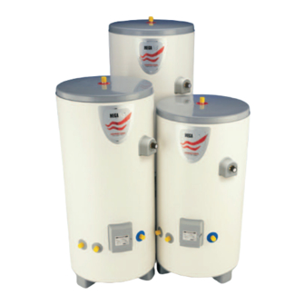
Introduction Congratulations on your purchase of a Heatrae Sadia Megaflo High Efficiency un- vented water heater. The Megaflo is manufactured in the UK from top quality materials and meets all the latest relevant safety and constructional standards. The high grade Duplex stainless steel cylinder offers exceptional strength and corrosion resistance which is backed by a 25 year guarantee. -
Page 4: General Requirements
EXPLAINED TO THE USER (SECTION 7) AND THESE INSTRUCTIONS LEFT WITH THEM FOR FUTURE REFERENCE. 2.1 COMPONENT CHECK LIST Before commencing installation check that all the components for your Megaflo unit are con- tained in the package. The following components are supplied as standard with your Megaflo unit : •... - Page 5 The Megaflo has an operating pressure of 3 bar which is controlled by the Cold Water Com- bination Valve. The Cold Water Combination Valve can be connected to a maximum mains supply pressure of 1.6 MPa (16 bar).
- Page 6 2.5 LIMITATIONS The Megaflo unvented water heater should not be used in any of the following instances: • Solid fuel boilers or any other boiler in which the energy input is not under effective ther mostatic control unless additional and appropriate safety measures are installed.
-
Page 7: Installation - General
The Cold Water Combination Valve can be connected anywhere on the cold water mains supply prior to the Megaflo unit. There is no requirement to site it close to the unit, it can be located at a point where the mains supply enters the premises if this is more conve- nient. - Page 8 Ensure the discharge from the Expansion Valve can be correctly installed. Figure 2 - Cold Water Combination Valve ISOLATING VALVE EXPANSION VALVE CONNECTION (IF ONE-PIECE VALVE IS REQUIRED) OUTLET TO MAINS IN MEGAFLO 22MM 22MM COMPRESSION COMPRESSION CONNECTION CONNECTION TAKE NOTE OF FLOW DIRECTION PRESSURE REDUCING...
- Page 11 If a secondary circulation system is required it is recommended that it be connected to the Megaflo as shown in Figure 6 via a Swept Tee joint (not supplied - available as an ac- cessory, order code no. 95 970 509). The secondary return pipe should be in 15mm pipe and incorporate a check valve to prevent backflow.
- Page 12 The Cold Water Combination Valve must be fitted to the mains water supply to the Megaflo unit. iii) No control or safety valves should be tampered with. iv) Water may drip from the discharge pipe of the pressure relief device (Expansion Valve) and this pipe must be left open to atmosphere.
- Page 13 3.10 DISCHARGE PIPEWORK It is a requirement of Building Regulations that any discharge from an unvented system is conveyed to where it is visible, but will not cause danger to persons in or about the building. The tundish and discharge pipes should be fitted in accordance with the requirements and guidance notes of Building Regulations.
- Page 14 d. have discharges visible at both the tundish and the final point of discharge, but where this is not possible or is practically difficullt there should be clear visibilty at one or other of these locations. Examples of acceptable discharge arrangements are: i.
- Page 15 Table 1 - Sizing of copper discharge pipe (D2) for common T&P relief valve sizes MINIMUM SIZE OF MINIMUM SIZE OF RESISTANCE CREATED BY VALVE OUTLET MAXIMUM RESISTANCE DISCHARGE PIPE D1 DISCHARGE PIPE D2 EACH ELBOW OR BEND SIZE ALLOWED, EXPRESSED FROM TUNDISH AS A LENTGH OF STRAIGHT PIPE (I.E.
-
Page 16: Installation - Direct Units
Installation - Direct units 4.1 IMMERSION HEATER(S) The Megaflo is supplied with either one (D models), two (DD models) or three (DDD models) factory fitted immersion heaters. Each immersion heater is rated 3kW at 240V. The DDD models are supplied with three immersion heaters and a blanking plug fitted to the uppermost of the three lower immersion heater bosses. - Page 17 DO NOT BYPASS THE THERMAL CUT-OUT(S) IN ANY CIRCUMSTANCES DISCONNECT FROM THE MAINS SUPPLY BEFORE REMOVING ANY COVERS NEVER ATTEMPT TO REPLACE AN IMMERSION HEATER OTHER THAN WITH THE REC- OMMENDED HEATRAE SADIA MEGAFLO SPARE PART Figure 9 - EARTH...
-
Page 18: Installation - Indirect Units
Installation - Indirect units 5.1 BOILER SELECTION The Megaflo Indirect (CL) models are suitable for use with most gas or oil fired boilers compat- ible with unvented systems i.e. fitted with a temperature control thermostat and thermal cut-out. If in doubt consult the boiler manufacturer. - Page 19 5.5 IMMERSION HEATER(S) The Megaflo indirect units (CL models) are supplied with an immersion heater which can be used as an alternative heat source should the boiler supply need to be isolated from the Megaflo unit. The immersion heater is located within the controls housing. Refer to Sec- tions 4.2 and 4.3 and Diagram 9 for details of wiring and operation of the immersion heater.
- Page 20 Figure 12 - Indirect controls housing details INDIRECT THERMAL CUT-OUT RESET BUTTON INDIRECT THERMOSTAT THERMAL ADJUSTMENT CUT-OUT INDIRECT THERMOSTAT CABLE CLAMPS TERMINAL BLOCK NOTE: THE HOUSING COVER AND ELEMENT ASSEMBLY HAVE BEEN REMOVED FROM THIS VIEW FOR CLARITY...
-
Page 23: Commissioning
Fill the indirect (primary) circuit following the boiler manufacturer’s commissioning instruc- tions. To ensure the primary heating coil in the Megaflo is filled the 2-port motorised valve (supplied) should be manually opened by moving the lever on the motor housing to the MAN OPEN setting. - Page 24 The log book should be left with the customer along with these instructions. The log book includes sections that should be filled in when any subsequent service or maintenance operation is carried out on the Megaflo.
-
Page 25: User Instructions
Indirect units (CL models) are fitted with an Indirect Thermostat which controls a 2-port motorised valve and hence the temperature of the water in the Megaflo unit. The thermo- stat is factory set to give a water storage temperature of approx. 60... - Page 26 To recharge the air volume :- Turn off the heat source to the cylinder via programmers/immersion isolation switch(es). Turn off the water supply to the Megaflo unit by turning off the isolating valve on the Cold Water Combination Valve.
-
Page 27: Maintenance
In hard water areas consideration should be given to periodically descaling the immersion heater elements. To do this the Megaflo unit will need to be drained, 8.4 and 8.5 below detail how to drain the unit and remove the immersion heater(s). - Page 28 A key spanner is supplied with the Megaflo unit for easy removal/tightening of the immersion heater(s). Over time the immersion heater gasket may become stuck to the mating surface. To break the seal insert a round bladed screwdriver into one of the pockets on the immersion heater and gently lever up and down.
-
Page 29: Fault Finding & Servicing
Caution must be taken when drawing water from the unit. 9.2 SPARE PARTS A full range of spare parts are available for the Megaflo range. Refer to the Technical Data label on the unit to identify the model installed and ensure the correct part is ordered. - Page 30 The Fault Finding chart overleaf (Table 2) will enable operational faults to be identified and their possible causes rectified. Any work carried out on the Megaflo unvented water heater and its as- sociated controls MUST be carried out by a competent installer for unvented water heating systems.
- Page 31 Table 2 - Fault Finding Chart FAULT POSSIBLE CAUSE REMEDY No hot water flow 1. Mains supply off 1. Check and open stop cock 2. Strainer blocked 2. Turn off water supply. Remove strainer and clean (see Section 8.3) 3. Cold Water Combination 3.
-
Page 32: Dimensions & Specifications
Dimensions & Specifications Figure 16 - Dimensions Direct units Temperature/Pressure Relief Valve Indirect units Temperature/Pressure Relief Valve... - Page 33 Table 3 - Dimensions Table 4 - Direct units - Technical specifications Table 5 - Indirect units - Technical specifications NOTE Coil heating performance based on a primary flow rate of 15 l/min at 80 Temperature rise is from 15 C to 60...
- Page 34 OUTLINE SPECIFICATIONS Maximum mains water supply pressure (to Cold Water Combination Valve) 1.6 MPa (16 bar) Operating pressure (Pressure reducing valve set pressure - non adjustable) 0.3 MPa (3 bar) Expansion relief valve set pressure 0.8 MPa (8 bar) Temperature/Pressure relief valve set temp/pressure C/1MPa (10 bar) Immersion heater rating (a.c.
-
Page 35: Guarantee
11.2 GUARANTEE TERMS Heatrae Sadia guarantee the electrical parts, thermal controls and valves for a period of two years, excluding the cold water control valve which is guaranteed for a period of five years, from the date of purchase, with the exception of damage due to scaling. -
Page 36: Contacts
Electric Water Heating Co. E-mail: heatraesadiaservice 2 Horsecroft Place, Pinnacles, @heateam.co.uk Harlow, Essex CM19 5BT ADDRESS Tel: 0845 0553811 Heatrae Sadia Heating E-mail: sales@ewh.co.uk Hurricane Way Norwich Norfolk Special Product Division NR6 6EA Units 9 & 10 Hexagon Business Centre...
Need help?
Do you have a question about the MEGAflo and is the answer not in the manual?
Questions and answers
I have a DD170 Mega flow, do both elements need to be on? If not. Which one has priority?