Table of Contents
Advertisement
Quick Links
Advertisement
Chapters
Table of Contents

Subscribe to Our Youtube Channel
Related Manuals for Kobold DZR


Summary of Contents for Kobold DZR
- Page 1 Operating Instruction Gear Wheel Flow Meter Model: DZR...
-
Page 2: Table Of Contents
14. Pressure Loss Diagrams ................13 15. Dimensions ....................13 16. Disposal ...................... 14 17. EU Declaration of Conformity DZR ............. 15 18. EU Declaration of Conformity SD1 .............. 15 19. Appendix: Operating Instruction for plug-on display SD1 Sold by:... -
Page 3: Note
Please read these operating instructions before unpacking and putting the unit into operation. Follow the instructions precisely as described herein. The instruction manuals on our website www.kobold.com are always for currently manufactured version of our products. Due to technical changes, the instruction manuals available online may not always correspond to the product version you have purchased. -
Page 4: Regulation Use
5. Operating Principle The KOBOLD Gear Wheel Flow Meter series DZR have been designed for a cost-effective flow measurement for viscous fluids. The measuring unit consists of a pair of gear wheels which is moved by the flow according to the principle of gear wheel motor. -
Page 5: Mechanical Installation
While doing so, adhere to the following tightening torque values. Tightening screws Tightening torque for connecting plates 001/003/ Measuring range code Tightening torque Nm • After starting up the process, check all connections for leakage. Tightening screws DZR K09/1023 page 5... -
Page 6: Electrical Connection
Pulse shape for symmetrical output signals Pulse displacement between the two 90° ± 30° channels Power requirement = 0.9 W b max Output power per channel = 0.3 W, short-circuit proof a max Protection type IP 65 page 6 DZR K09/1023... - Page 7 Channel 2 signal indication channel 2 cable gland Channel 1 signal indication channel 1 24 Volt Attention! Once mounting is completed the securing screw and the cable gland must be tightened. Be careful not to over-tighten. DZR K09/1023 page 7...
-
Page 8: Signal Characteristics
Remove the pipe connections from the housing and if necessary, remove the housing from the holding device. Attention! When using media that hardens, clean the Gear Wheel Flow Meter with a suitable cleansing agent as promptly as possible. page 8 DZR K09/1023... -
Page 9: Commissioning
8.1. Permitted Operating Limits Attention! The flow resistance ∆p must not exceed 16 bar, otherwise it leads into mechanical damage. The ambient conditions must comply with the limits given in the technical specifications. DZR K09/1023 page 9... -
Page 10: Maintenance
10. Cleaning DZR-1/2/5 and 6 units: Never open these particular units yourself, as they can only be re-assembled in working order by a specialist. Attention! Ensure that the pipes are de-pressurised and the electrical connection is powerless. - Page 11 (see below). Attention! All parts must be free of contamination. Ensure that no contaminants remain inside the Gear Wheel Flow Meter. Tightening torque for securing the housing, DZR-3 and DZR-4 Measuring range code Tightening torque •...
-
Page 12: Recognising And Correcting Faults
Send Models DZR-1 and 2 measuring unit has stopped units to the manufacturer for repair. Models DZR-3 and 4 units can be dismounted and cleaned (see under "Maintenance") Leakage, escaping medium Faulty O ring in housing. -
Page 13: Technical Information
12. Technical Information Operating instructions, data sheet, approvals and further information via the QR code on the device or via www.kobold.com 13. Order Details Operating instructions, data sheet, approvals and further information via the QR code on the device or via www.kobold.com 14. -
Page 14: Disposal
(Cd, Hg, Li or Pb) of the heavy metal that is decisive for the classification as containing pollutants: 1. „Cd" stands for cadmium 2. „Hg" stands for mercury 3. „Pb" stands for lead 4. „Li" stands for lithium Electrical and electronic equipment page 14 DZR K09/1023... -
Page 15: Eu Declaration Of Conformity Dzr
17. EU Declaration of Conformity DZR We, KOBOLD Messring GmbH, Nordring 22-24, 65719 Hofheim, Germany, declare under our sole responsibility that the product: Gear Wheel Flow Meter Model: DZR-… to which this declaration relates is in conformity with the following EU directives... -
Page 16: Eu Declaration Of Conformity Sd1
18. EU Declaration of Conformity SD1 We, KOBOLD Messring GmbH, Nordring 22-24, 65719 Hofheim, Germany, declare under our sole responsibility that the product: Plug-on display Model: SD1 to which this declaration relates is in conformity with the following EU directives... - Page 17 O p e r a t i n g I n s t r u c t i o n s...
- Page 18 1. SAFETY 2. DESCRIPTION 3. CONNECTING THE SD1 3.1 Connecting the voltage supply 3.2 Connecting SD1 with rectangular output. 3.3 Connecting the SD1 with analog output 3.4 Connecting the SD1 with relay contacts. 3.5 How is the flow rate measurement activated ? 3.6 How is the volume measurement activated ? 3.7 Error display 4.
-
Page 19: Safety
1. Safety The safety notes included in these operating instructions are indicated by this ‘attention-getter’ symbol. If the text accompanying this symbol is not heeded, danger to personnel or equipment may result. Other instructions, which are not safety warnings, but which give advice on optimum operation, are indicated by a hand. -
Page 20: Description
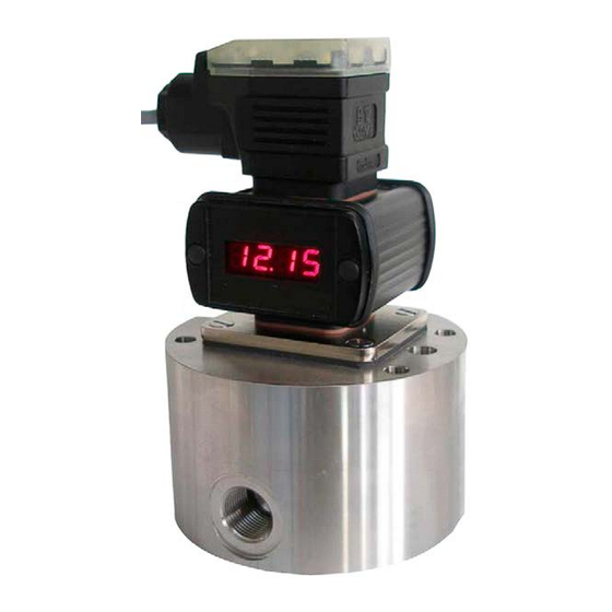
2. Description The plug-in display unit SD 1 may be used with any KOBOLD volume counter which uses a plug-in connection according to DIN 43650. The display unit is simply inserted between the plug and the plug socket on the volume counter. -
Page 21: Connecting The Sd1
3. Connecting the SD1 This section deals with the layout of the connections on the SD1. The electrical connection has to be made by a plug-in connection acc. to DIN 43650. 3.1 Connecting the voltage supply The SD1 is operated with an voltage of 24 VDC or 12 VDC. The adjustment is achieved by means of solder jumpers. -
Page 22: Connecting The Sd1 With Analog Output
3.3 Connecting the SD1 with analog output The SD1 is available in 3 versions SD1-R with two rectangular signals with a pulse offset of 90°, SD1-I with analog output (0-20 mA/4-20 mA), SD1-K with relay contact. Connections are different in every serial-model modification. Option with analog output (0-20mA/4-20 mA): Connection of analog output has to be made on clamps. -
Page 23: Connecting The Sd1 With Relay Contacts
3.4 Connecting the SD1 with relay contacts. The SD1 is available in 3 models: SD1-R with two rectangular signals with a pulse offset of 90°, SD1-I with analog output (0-20 mA/4-20 mA), SD1-K with relay contact. Connections are different in every serial-model modification. Option with relay contact: The SD1 has two relay contacts. -
Page 24: How Is The Flow Rate Measurement Activated
3.5 How is the flow rate measurement activated ? The SD1 can be switched to flow measurement or volume measurement. This will be made by programming SD1 under menu “7” at step “display”. The flow rate will be adjusted by “0” and the volume by “1”. (see 4.1 for overview of input values). -
Page 25: How Is The Volume Measurement Activated
3.6 How is the volume measurement activated ? The SD1 can be switched to flow measurement or volume measurement. This will be made by programming SD1 under menu “7” at step “display”. The flow rate will be adjusted by “0” and the volume by “1”. (see 4.1 for overview of input values). -
Page 26: Error Display
3.7 Error display On two channel volume counters it is possible to monitor the correct pulse sequence on the channels. Faulty pulses are not counted and thus do not change the volume measurement. If an error is established by the SD1, the character sequence “FAUL“ appears in the display. -
Page 27: Sd1 Programming
4. SD1 programming Each time the SD1 is to be operated, it is necessary to adapt the unit to the volume counter that is connected. Input procedure: The input procedure is the same for all input values and is therefore described once only. -
Page 28: Overview Of The Input Values
4.1 Overview of the input values The values which are required to be set can be inserted in the column labelled “Input value-User”. Menu – Input value - Standard Function Unit Reference User setting 0.040 Pulse volume of volume counter 3.500 Maximum value Analogue output 0.400... -
Page 29: What Must Be Programmed When Connecting A Volume Counter
“00 - pulse volume counter”, menu reference “09 - density”, and under menu reference “08” at the position “counter input”. The pulse volumes for KOBOLD Volume counters can be obtained from the Table. The “X” characters in the “Input value Menu reference 08“ column are of no significance in setting the volume counter. -
Page 30: How To Change Time On Flow Display
4.3 How to change time on flow display ? You can choose between second, minute and hour to change time on flow display by adjusting menu 07. Setting the time base: Time base Input value Menu reference 07 Minutes XX00 Minutes XX10 Seconds... -
Page 31: How To Find Out The Flow Rate
4.4 How to find out the flow rate? The SD1 commands two measuring systems to determine the flow: duration of period or measurement of pulse width and gate time. You can choose between “gate time measurement” or “ duration of period measurement”... -
Page 32: What Must Be Programmed When Connecting The Relay Outputs
4.5 What must be programmed when connecting the relay outputs ? Relay function can be adjusted only if the instrument was ordered with option relay contacts (SD1-K.). The relays can be allocated to flow rate or volume measurement. Flow rate measurement A “0”... -
Page 33: What Must Be Programmed When Connecting The Analogue Output
4.6 What must be programmed when connecting the analogue output ? The analog output can be used only if the instrument was ordered with analog output (SD1-I...). The analogue output can be assigned to flow rate or volume measurement. Flow rate measurement A “0”... -
Page 34: Technical Data
5. Technical Data PIC 17C42 Processor Power pack 18 VDC – 28 VDC optional 10 – 19 VDC Supply ca. 120 mA Maximum input current General data Principle : 7 Segment LED, 7,62 mm, red Display Display :0.000 ... 9999 with floating point overrun ( >9999 ) : display 9999 Control keys Two keys behind the front cover... -
Page 35: Type Code
6. Type code Example : SD1 - R - 24 / . Identification for programs volume measurement only with version SD1-I or SD1-K; volume measurement with SD1-R on request. 24 VDC Power supply 12 VDC Power supply Square wave signals (incremental signal) Current output 0-20 mA, 4-20 mA Relay outputs Page 19... -
Page 36: Connections
7. Connections The electrical connections are made by a plug-connection DIN 43650 Connections Version SD1-R-24 PIN 1 = UB+ PIN 2 = GND PIN 3 = Channel 1 = Channel 2 Connections Version SD1-I-24 PIN 1 = UB+ PIN 2 = GND PIN 3 = Analogue output 0/4-20 mA...
Need help?
Do you have a question about the DZR and is the answer not in the manual?
Questions and answers