Table of Contents
Advertisement
Quick Links
Advertisement
Table of Contents

Subscribe to Our Youtube Channel
Related Manuals for Kobold DON Series


Summary of Contents for Kobold DON Series
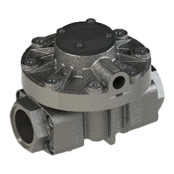
- Page 1 Operating Instructions Oval Gear Flow Meter Model: DON-...
-
Page 2: Table Of Contents
1. Contents Contents ......................2 Note ......................4 Instrument Inspection ..................7 Regulation Use ..................... 7 Operating Principle ..................8 Mechanical Connection ................. 8 General ....................8 ... - Page 3 Manufactured and sold by: Kobold Messring GmbH Nordring 22-24 D-65719 Hofheim Tel.: +49(0)6192-2990 Fax: +49(0)6192-23398 E-Mail: info.de@kobold.com Internet: www.kobold.com DON K36/1222 page 3...
-
Page 4: Note
Please read these operating instructions before unpacking and putting the unit into operation. Follow the instructions precisely as described herein. The instruction manuals on our website www.kobold.com are always for currently manufactured version of our products. Due to technical changes, the instruction manuals available online may not always correspond to the product version you have purchased. - Page 5 as per PED 2014/68/EU DON-1/3 Aluminum-Version diagram 8 diagram 9 Model DON-1/3 [bar group 1 group 2 dangerous liquids no dangerous liquids DON- x 04 ⅛ DON- x 05 ⅛ DON- x 10 ¼ DON- x 15 ⅜ DON- x 20 ½...
- Page 6 DON-1 M4 Aluminum version with mechanical totalizer diagram 8 diagram 9 Option M4 [bar group 1 group 2 Model DON-1/3 dangerous liquids no dangerous liquids DON- x 04 ⅛ DON- x 05 ⅛ DON- x 10 ¼ DON- x 15 ⅜...
-
Page 7: Instrument Inspection
3. Instrument Inspection Instruments are inspected before shipping and sent out in perfect condition. Should damage to a device be visible, we recommend a thorough inspection of the delivery packaging. In case of damage, please inform your parcel service / forwarding agent immediately, since they are responsible for damages during transit. -
Page 8: Operating Principle
Chemical compatibility of the liquid. Be sure that all wetted parts are identified and confirmed suitable for use with the media being measured. If unsure, please contact a KOBOLD engineer for guidance in obtaining the proper reference materials. Verify that the operational pressure and temperature limits are within capability of the fully specified meter. -
Page 9: Orientation
6.2 Orientation When installing the flowmeter, orientation must be considered. The rotor shafts must be in a horizontal plane. To verify that the rotor shafts are in a horizontal plane, electronic cover or optional digital display will be facing in a horizontal direction. -
Page 10: Flow Conditioning And Location
6.3 Flow Conditioning and Location It is highly recommended to INSTALL a filter immediately before (prior to) the meter. Filters are available and sold separately. Recommended Filter (e.g. MFR-DO...): DON-x04…DON-x15: < 75 µm particle size (200 mesh) DON-x20…DON-x35: < 150 µm particle size (100 mesh) DON-x40…DON-x60: <... -
Page 11: Electrical Connection
7. Electrical Connection 7.1 Connecting Cable Proper shielded instrument cable is highly recommended. Low capacitance twisted pair 7 x 0.3 mm (0.5 mm²) for use with the DON and any remote receiving instrumentation. Typical cable would be Belden® 9363 or similar. Connect the cable shield to DC common or designated grounding terminal at the receiving instrument. - Page 12 The HU electronics option provides the NPN output with built-in 4.7 kΩ pull-up resistor. The external supply voltage is 5-30 VDC and the max. switching current is 200 mA (short-circuit protected). Note! The electronic options H0/HE/HA/HU are available with reed switch output while all other options are equipped without additional reed switch.
- Page 13 The individually specified maximum electrical values of the reed switch must never be exceeded, even for a moment. Higher switching values may reduce the service life or even destroy the contact. For capacitive and inductive loads (e.g. via long lines), we recommend the following protective circuits: Lamp load with series or parallel Protection with a RC suppressor...
- Page 14 7.2.3 Quadrature Pulse Output (QUAD, Option D0/DE/DA) For the D0/DE option, the DON devices come with 2 independent hall-sensor elements. The hall-effect sensors are arranged so that they emit separate phase- shifted signals to one another. The QUAD output is best-suited for verified use with a redundant signal or for counting bidirectional currents (detecting the current direction).
-
Page 15: Internal Wiring With Electronic Options -Zx
7.3 Internal wiring with electronic options –Zx The -Zx electronic options are pre-configured ex works in connection with the sensor boards. Reconfiguration is available on request. 7.3.1 For Z1/Z2/Z3/Z5 electronic options (reed switch and Hall sensor) a) Wiring diagram with reed switch (ex works standard, mandatory for supply with battery or in the 2-wire 4-20 mA operation) DON K36/1222 page 15... - Page 16 b) Wiring diagram with Hall sensor (not for battery operation, recommended in connection with external supply) 7.3.2 For Z6/Z7 electronics options (bipolar Hall sensor) The circuitry corresponds to 7.3.1 b.) 7.3.3 For 1A...5A electronics options Refer operating instructions supplement ZOK-Ex wiring options 1A...5A page 16 DON K36/1222...
- Page 17 7.3.4 For Z2/Z8/Z9 electronics options (2 Hall sensors for direction detection) DON K36/1222 page 17...
- Page 18 7.3.5 Analog output 4-20 mA, 2-line (L0/LE option) The L0 and LE (explosion hazard) options include a loop-powered 4-20 mA output. The loop is powered by an external voltage source 16 – 32 V . The maximum working resistance of loads connected in series (PLC-analogue input / electronic displays) depends on the supply voltage level, namely: Max.
-
Page 19: External Wiring With Electronic Unit Zok-Zx
7.4 External wiring with electronic unit ZOK-Zx 7.4.1 Wiring with ZOK-ZxK a) Circuit with Hall sensor (not for battery operation) b) Circuit with Reed switch (only for battery or 4-20mA loop operation, shielded connection cable is recommended, shield on GND) DON K36/1222 page 19... - Page 20 7.4.2 Wiring with ZOK-ZxP a) Circuit with Hall sensor b) Circuit with Reed switch (shielded connection cable is recommended, shield on GND) page 20 DON K36/1222...
-
Page 21: Commissioning
8. Commissioning The piping MUST be flushed of debris before installation. Debris such as slag from welding, grinding dust, rust, pipe tape or sealing compound are common within new piping installations and will damage the flowmeter if not flushed or filtered from the process piping before installation and operation. -
Page 22: Maintenance
9. Maintenance Flowmeter maintenance precautions: Remove/disconnect power to the flowmeter. Ensure that flow supply to the meter is turned off and the system is not under pressure. Completely drain the flowmeter Confirm that any signal output(s) will not affect the system when de- energized or removed from the circuit. -
Page 23: Disassembly Of Don With Pulse Meter
9.1 Disassembly of DON with Pulse meter Concerning options Hx, Dx, Gx, Bx, Kx and Bx 9.1.1 Pulse output board removal (refer exploded view diagram) To remove the pulse output board, remove the 4 electronic cover screws (10), and remove the electronic cover (9). The pulse output board (6) can now be accessed and removed via the removal of the electronic board screws (7). - Page 24 9.1.3 Removal of oval gears for DON-x20 (refer exploded view) For access to the oval gears, remove the 6 upper meter body screws (5). With care, remove the upper meter body assembly (4) being careful not to damage or misplace the O-ring (3). You can then remove the oval gears (2). Optional page 24 DON K36/1222...
- Page 25 9.1.4 Removal of oval gears for DON-x25…DON-x40 (refer exploded view) For access to the oval gears, remove the 8 upper meter body screws (5). With care, remove the upper meter body assembly (4) being careful not to damage or misplace the O-ring (3). You can then remove the oval gears (2). Optional DON K36/1222 page 25...
- Page 26 9.1.5 Removal of oval gears for DON-x45…DON-x60 (refer exploded view) For access to the oval gears, remove the 8 upper body screws (5). With care, remove the upper body assembly (4) being careful not to damage or misplace the O-ring (3). You can then remove the oval gears (2). Optional page 26 DON K36/1222...
- Page 27 9.1.6 Structure of the DON-M4 mechanical counting mechanism Loosen three screws (10) Remove cover (9) Lift out counting mechanism (8) Remove seal (7) Loosen 4 screws (6) Remove lower housing section (5) Remove seal (4), washer (3) and seal (2). When assembling, it is important to ensure the oval gear of (3) is correctly positioned relative to the counting mechanism (8).
- Page 28 DON-x25 to x40 DON-x45 to x60 page 28 DON K36/1222...
- Page 29 9.1.7 Adjusting the DON-M4 mechanical counter mechanism The M4 mechanical counter display comprises a 4-digit mechanical totalizer (1) and an 8-digit sum display (2). Depending on the order option, the display is calibrated in either litres or gallons. The totalizer display can be reset to zero by turning the function dial (3) in an anti- clockwise direction.
-
Page 30: Demounting Of The Electronics Mounted On A Don With Option Zx Or 1A
9.3 Spare Parts Please consult your closest KOBOLD-Office Internet: www.kobold.com or www.koboldusa.com 9.4 Inspection (refer Exploded View) Inspection points will be the following: O-rings –... - Page 31 9.5.1 Re-assembly of DON-x04...DON-x15 The small flow meters (DON-x04 to -x10) have dimples on both housing parts (1 and 4). These markings must be matched during assembly. Only one oval gear is equipped with magnets in these small flow meters. The oval gear without magnet must be mounted on the axis that is closest to the dimple.
- Page 32 9.5.2 Re-assembly of DON-x20...DON-x40 Both oval gears are placed on the axle shafts with the magnets oriented towards the upper meter body (4). Verify that the axle shafts are not loose. Both oval gears are equipped with embedded magnets, allowing them to each be mounted on either axle.
- Page 33 Exploded view of DON-x45...DON-x60 Optional Table tightening torque Housing screws Connections and axes Model x04...x15 x20...x25 x20...x25* x30...x40 x45...x60 Steel screws with Geomet coating for high pressure version DON K36/1222 page 33...
-
Page 34: Technical Data
10. Technical Data Operating instructions, data sheet, approvals and further information via the QR code on the device or via www.kobold.com 11. Pressure drop curves Operating instructions, data sheet, approvals and further information via the QR code on the device or via www.kobold.com 12. -
Page 35: Disposal
14. Disposal Note! Avoid environmental damage caused by media-contaminated parts Dispose of the device and packaging in an environmentally friendly manner Comply with applicable national and international disposal regulations and environmental regulations. Batteries Batteries containing pollutants are marked with a sign consisting of a crossed-out garbage can and the chemical symbol (Cd, Hg, Li or Pb) of the heavy metal that is decisive for the classification as containing pollutants: 1. -
Page 36: Troubleshooting
15. Troubleshooting Oval gear flowmeters have two clearly distinct portions: one of which is mechanical, wetted areas with the oval gears surrounded by a housing, and the other is the electrical area, which includes the pulse output board. Details of some key troubleshooting steps will now be provided. Please also refer to the instructions on troubleshooting errors contained on the following page. - Page 37 Problem Possible cause Solution 1. Ground shielding of the signal cable 1. Disruption of the output signal 2. Re-lay the cable away from sources of high current 1. Eliminate the source of the air or gas pocket 2. Air or gas pockets 2.
-
Page 38: Use In Ex Areas
16.1 General information The flow meter is intended for commercial systems and may only be used in accordance with the information in the technical documentation from Kobold and the information on the nameplate. It is operated exclusively together with certified products via an intrinsically safe circuit. - Page 39 b) If the instructions given here are not followed or if the product is handled improperly, our liability is void. In addition, the warranty on products and spare parts does not apply. c) The products are not safety elements in the sense of their intended use. d) Only original parts from the manufacturer may be used.
- Page 40 16.1.4 Servicing, maintenance Definition of terms according to IEC 60079-17: Maintenance and repair: A combination of all activities carried out in order to keep an object in a condition or to bring it back into a condition that meets the requirements of the relevant specification and ensures the execution of the required functions.
-
Page 41: Atex Version Exi (Electronics Options Xa)
16.1.5 Troubleshooting No changes may be made to products that are operated in connection with potentially explosive areas. Repairs to the product may only be carried out by specially trained and authorized specialists. 16.1.6 Disposal The packaging and used parts must be disposed of in accordance with the regulations of the country in which the product is installed. - Page 42 External earthing clamp 16.2.2 Electrical parameters of the electronic options HA/BA/GA/KA/DA when used in Zone 1/2 Electrical data: Pi ≤ 1 W @ max. 80 ° C ambient temperature Electronics Use in zone option Hall sensor 270 nF HA/BA/GA/KA/DA ≤...
- Page 43 16.2.3 Wiring examples for electronics options HA/KA/BA/GA with Zener barriers Control Drawing for DON-***HA Oval Gear Flowmeter with pulse output (Reedswitch, usage with zener barrier) for Group IIB zone 1 Safe Area Hazardous Area Flowmeter DON-* ** ** ** HA * * Group IIB, zone 1 -20 °C ≤...
- Page 44 Control Drawing for DON-HA/KA/BA/GA Oval Gear Flowmeter with pulse output (Hallsensor, usage with zener barrier) for group IIB zone 1 Safe Area Hazardous Area Flowmeter DON-* ** ** ** HA * * Group IIB, zone 1 -20 °C ≤ Ta ≤ 60 °C simple apparatus Zener barrier 300R...
- Page 45 16.2.5 Commissioning, installation Depending on the IP degree of protection, the time for cleaning the equipment (dust deposits) must be specified. Other important facts: a) The product may only be put into operation in Zone 2 (Cat. 3G, EPL Gc) or in Zone 1 (Cat.
- Page 46 s) The ignition limit curves from EN 60079-11 must be taken into account in Zone 2 without a safety factor and must be observed during installation. The safety factor 1.5 is to be used in zone 1. A control drawing (system description) to be created by the installer / operator is required for the installation of the intrinsically safe circuit.
- Page 47 16.2.6 Identification of the flow meter (nameplate) Basic device label DON- (example) Device label for Ex version intrinsically safe, options HA / GA / DA / KA / BA (example) DON K36/1222 page 47...
-
Page 48: Atex Exd Version (Electronic Options Be/He/De/Ge/Ke/Le)
16.3 ATEX Exd version (electronic options BE/HE/DE/GE/KE/LE) 16.3.1 General information Products which were ordered with the optional encapsulated pressure-proof connector housing (Exd) are marked with an ATEX label (see figure). The label includes details relating to explosion group and temperature class. Before installing and operating the device, the label should be checked to ensure it contains all the required details. - Page 49 16.3.2 Electrical connection In accordance with the installation regulations, both the housing and the electronics cover must be grounded using the attached grounding clamps. The maximum connection cross-section is 4 mm Internal earthing clamp electronics cover External ground terminal The installer must ensure that the maximum supply voltage of 28 Vdc and the maximum current of 100 mA are not exceeded.
-
Page 50: Eu Declaration Of Conformance
17. EU Declaration of Conformance We, KOBOLD Messring GmbH, Hofheim-Ts, Germany, declare under our sole responsibility that the product: Oval Gear Flow Meter Model: DON-... to which this declaration relates is in conformity with the standards noted below: EN IEC 63000:2018 Technical documentation for the assessment of electrical... - Page 51 Also complies with the following European and national standards and technical regulations: Technical rules for hazardous substances (TRGS) 727: 2016, avoidance of ignition hazards due to electrostatic charges Hofheim, 08 Feb. 2022 H. Volz M. Wenzel General Manager Proxy Holder DON K36/1222 page 51...
-
Page 52: Declaration Of Conformance
18. UK Declaration of Conformance We, KOBOLD Messring GmbH, Hofheim-Ts, Germany, declare under our sole responsibility that the product: Oval Gear Flow Meter Model: DON-... to which this declaration relates is in conformity with the standards noted below: BS EN IEC 63000:2018... -
Page 53: Statement Of Conformity
19. Statement of Conformity DON K36/1222 page 53... - Page 54 page 54 DON K36/1222...
- Page 55 DON K36/1222 page 55...
- Page 56 page 56 DON K36/1222...
- Page 57 DON K36/1222 page 57...
-
Page 58: Exd Certificate
20. Exd Certificate page 58 DON K36/1222... - Page 59 DON K36/1222 page 59...
- Page 60 page 60 DON K36/1222...
-
Page 61: Iecex Certificate
21. IECEx Certificate DON K36/1222 page 61... - Page 62 page 62 DON K36/1222...
- Page 63 DON K36/1222 page 63...
- Page 64 page 64 DON K36/1222...
-
Page 65: State Of Safeness
22. State of safeness DON K36/1222 page 65...
Need help?
Do you have a question about the DON Series and is the answer not in the manual?
Questions and answers