Table of Contents
Advertisement
Quick Links
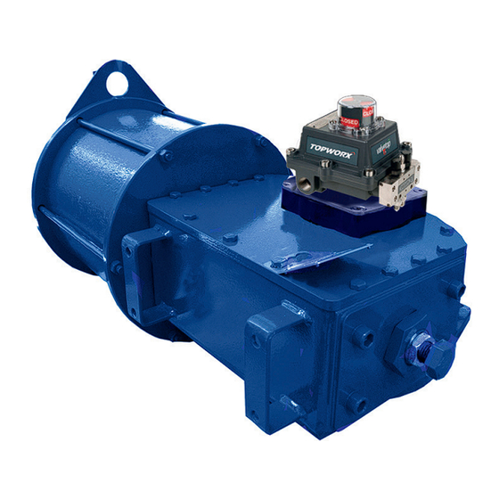
Biffi ALGA
Double-Acting Pneumatic Actuator
Copyright © Biffi. The information in this document is subject to change without notice. Updated installation, operation and maintenance manuals can be obtained from our website
www.biffi.it or from your nearest Biffi Center: Biffi Italia s.r.l. - Strada Biffi 165, 29017 Fiorenzuola d' A rda (PC) – Italy PH: +39 0523 944 411 – biffi_italia@biffi.it
Installation, Operation and Maintenance Manual
MAN 564 Rev. 8
July 2024
Advertisement
Table of Contents
Troubleshooting

Related Manuals for BIFFI ALGA


Summary of Contents for BIFFI ALGA
- Page 1 Copyright © Biffi. The information in this document is subject to change without notice. Updated installation, operation and maintenance manuals can be obtained from our website www.biffi.it or from your nearest Biffi Center: Biffi Italia s.r.l. - Strada Biffi 165, 29017 Fiorenzuola d’ A rda (PC) – Italy PH: +39 0523 944 411 – biffi_italia@biffi.it...
- Page 2 Notes Installation, Operation and Maintenance Manual July 2024 MAN 564 Rev. 8 This page is intentionally left blank.
-
Page 3: Table Of Contents
Operation Description ..................20 Residual Risks ......................27 Calibration of the Angular Stroke ...............27 Calibration of Microswitches ................34 Calibration of the Operation Time (Biffi Limit Switch Box Only) ....34 Section 4: Operational Tests and Inspections Operational Tests and Inspections ................36 Section 5: Maintenance Periodic Maintenance ...................37... - Page 4 Table of Contents Installation, Operation and Maintenance Manual July 2024 MAN 564 Rev. 8 Section 6: Troubleshooting Failure or Breakdown Research ................56 Section 7: Spare Parts Spare Parts Order ....................57 Parts List for Maintenance and Replacement Procedure ......58 Section 8: Date Report for Maintenance Operations Date Report for Maintenance Operations ..............68 Table of Contents...
-
Page 5: Section 1: General Warnings
Installation, Operation and Maintenance (IOM) Manual. However, Biffi Italia s.r.l. is not liable for any mistakes contained in this manual for damage or accidents due to the use of the latter. The information contained is of exclusive reserved ownership of Biffi Italia s.r.l. -
Page 6: Identification Plate
The actuator yoke has a hole with keyways suitable for the assembly of an insert bush the internal hole of which is machined (by Biffi or at customer’s care), according to the shape and dimensions of the valve stem. Biffi can supply different types of control system following customers requirements. -
Page 7: Data Sheet
Manual hand pump - MHP (optional) Valve position indicator Pneumatic cylinder Scotch yoke mechanism Hydraulic cylinder for ALGA-MHP models or second pneumatic cylinder for ALGA* two double cylinder models (optional) Valve coupling NOTE: * C or S canted or symmetric... -
Page 8: Section 2: Installation
Section 2: Installation Installation, Operation and Maintenance Manual July 2024 MAN 564 Rev. 8 Section 2: Installation Checks Upon Actuator Receipt • Check that the model, the serial number of the actuator and the technical data reported on the identification plate correspond with those of order confirmation (Section 1.2). - Page 9 Installation, Operation and Maintenance Manual Section 2: Installation MAN 564 Rev. 8 July 2024 Figure 4. Lifting Points for ALGA/ALGA-MHP/ALGA-MSJ Actuators (1) 1, 2 = Lifting points (obligatory) = Balancing point Figure 5. Lifting Points for ALGA/ALGA-MHP/ALGA-MSJ Actuators (2) 1 = Point of support...
- Page 10 BIFFI IS NOT LIABLE FOR ANY PERSONEL INJURY DUE TO INCORRECT USE REFFER TO IOM WARNING Any lifting method different from what described above is strictly forbidden. Biffi rejects any responsibility for damages to goods or injuries to personnel coming from wrong lifting operations. Installation...
-
Page 11: Storage
For coupling to the valve, the housing is provided with a flange with threaded holes according to Biffi standard tables (Tables 1 to 7. Please refer to the plant for additional details). The number, dimensions and diameter of the holes are made in accordance with ISO 5211, but for actuator models 0.3 to 6 the holes are drilled on... - Page 12 MAN 564 Rev. 8 The yoke has bored with keyways for coupling to the valve stem, the dimensions of which are according to Biffi standard tables (Tables 1 to 7. Please refer to the plant for additional details). Figure 7.
- Page 13 Installation, Operation and Maintenance Manual Section 2: Installation MAN 564 Rev. 8 July 2024 Figure 8. Coupling Dimensions - Models 0.3 to 6 DRIVE SLEEVE Ød +0.1 Ød Ød ±0.2 Ød N. THREADED HOLES PCD, NUMBER AND SIZE ACCORDING TO ISO 5211 (BUT THE HOLES ARE ON CENTERLINE INSTEAD OF STRADDLE THE CENTERLINE) FLOW LINE...
- Page 14 Section 2: Installation Installation, Operation and Maintenance Manual July 2024 MAN 564 Rev. 8 Figure 9. Coupling Dimensions - Model 14 DRIVE SLEEVE Ød +0.1 Ød Ød ±0.2 Ød N. THREADED HOLES PCD, HOLES, NUMBER AND SIZE ACCORDING TO ISO 5211 FLOW LINE Ød +0.2...
- Page 15 Installation, Operation and Maintenance Manual Section 2: Installation MAN 564 Rev. 8 July 2024 Figure 10. Coupling Dimensions - Models 18 to 42 DRIVE SLEEVE Ød +0.1 Ød Ød ±0.2 Ød N. THREADED HOLES PCD, HOLES, NUMBER AND SIZE ACCORDING TO ISO 5211 FLOW LINE +0.2...
- Page 16 Section 2: Installation Installation, Operation and Maintenance Manual July 2024 MAN 564 Rev. 8 Figure 11. Coupling Dimensions - Models 50 and 60 DRIVE SLEEVE Ød +0.1 Ød Ød ±0.2 Ød N. THREADED HOLES FLOW LINE Ød +0.2 +0.1 TOP VIEW OF THE SCOTCH YOKE MECHANISM (ACTUATOR SHOWN IN CLOSED POSITION) Table 5.
- Page 17 Installation, Operation and Maintenance Manual Section 2: Installation MAN 564 Rev. 8 July 2024 Figure 12. Coupling Dimensions - Models 65 and 80 DRIVE SLEEVE +0.1 Ød Ød Ød ±0.2 Ød N. THREADED HOLES PCD, HOLES, NUMBER AND SIZE ACCORDING TO ISO 5211 FLOW LINE +0.2 Ød...
- Page 18 Section 2: Installation Installation, Operation and Maintenance Manual July 2024 MAN 564 Rev. 8 Figure 13. Coupling Dimensions - Model 100 DRIVE SLEEVE Ød +0.1 Ød Ød ±0.2 Ød N. THREADED HOLES PCD, NUMBER AND SIZE ACCORDING TO ISO 5211 (BUT THE HOLES ARE ON CENTERLINE INSTEAD OF STRADDLE THE CENTERLINE) FLOW LINE...
- Page 19 A-A from position 1 Insert bush turned upside down The Biffi insert bush with 2 external keys at 45° allows to position the keyway for the valve every 90°. Consequently, the actuator can be mounted in 4 positions at 90° on top of the valve.
-
Page 20: Assembly Procedure
Section 2: Installation Installation, Operation and Maintenance Manual July 2024 MAN 564 Rev. 8 2.4.2 Assembly Procedure NOTICE Failure to comply with the following procedures may void product warranty. WARNING Installation, commissioning and maintenance and repair works should be carried out by qualified staff. A non-conforming assembly could be the source of serious accidents. -
Page 21: Pneumatic Connections
Check the absence of leakages from pneumatic connections. NOTICE If it is necessary to mount components not in Biffi scope of supply, please check the accessories mounting hole details in the documents TN 1028 (for metric dimension) or TN 1028U (for imperial dimension). -
Page 22: Electrical Connections (If Any)
Section 2: Installation Installation, Operation and Maintenance Manual July 2024 MAN 564 Rev. 8 Electrical Connections (If Any) WARNING Use components appropriate as per type, material and dimensions. The connections should be made by qualified staff. Before carrying out any operation, cut line power off. Safety provisions: 2006/95/EC: Directive for low voltage equipment (until 19 April 2016) -
Page 23: Commissioning
Installation, Operation and Maintenance Manual Section 2: Installation MAN 564 Rev. 8 July 2024 Commissioning WARNING Check to see if the values of electrical supply to the control group (if foreseen) are compatible with those on the plate on the junction box (Figure 15). Installation, commissioning and maintenance and repair works should be made by qualified staff. -
Page 24: Section 3: Operation And Use
Section 3: Operation and Use Operation Description In the normal operating situation, the ALGA actuator is fed by pressurized gas which flows into the relevant cylinder chamber (for example opening). The cylinder piston stroke causes the actuator operation and the consequent valve movement to the operational position requested (in this case to the “open”... - Page 25 Installation, Operation and Maintenance Manual Section 3: Operation and Use MAN 564 Rev. 8 July 2024 Figure 17. ALGA Actuator Parts Table 10. Parts List Item Name Housing Yoke Yoke bushing Cover Guide block pin Sliding block Guide block Guide bar...
- Page 26 Section 3: Operation and Use Installation, Operation and Maintenance Manual July 2024 MAN 564 Rev. 8 For local or remote operations, please refer for information only to Figures 18 to 23 and prior to technical documentation furnished with actuators. Typical schematics for various applications are follow attached for information only, the function described are fournished only on specific customer demand.
- Page 27 Installation, Operation and Maintenance Manual Section 3: Operation and Use MAN 564 Rev. 8 July 2024 Figure 19. On/Off Service: Air Fail Safe Aystem PRESSURIZED AIR PRESSURIZED AIR (LOW PRESSURE) ATMOSPHERIC PRESSURE AIR The system allows ‘fail-safe’ operation when the pressure in the gas supply line drops below a set value.
- Page 28 Section 3: Operation and Use Installation, Operation and Maintenance Manual July 2024 MAN 564 Rev. 8 Figure 20. Modulating Service ELECTROPNEUMATIC POSITIONER PNEUMATIC ELECTRIC PNEUMATIC CONTROL SIGNAL CONTROL SIGNAL POSITIONER PRESSURIZED AIR (SUPPLY) REDUCED PRESSURE AIR (OPENING CHAMBER) REDUCED PRESSURE AIR (CLOSING CHAMBER) When modulating control is required as a function of a pneumatic or electric control signal, a positioned (5) is used, which controls the supply to the actuator cylinder to keep the valve in the required angular position.
- Page 29 Installation, Operation and Maintenance Manual Section 3: Operation and Use MAN 564 Rev. 8 July 2024 Figure 21. Emergencency Manual Override ENGAGED TO OPEN INNESTATO APERTURA DISENGAGED TO CLOSE DISINNESTATO CHIUSURA For models up to three, the MHW-MSJ jackscrew manual override can be provided. The jackscrew end of the override is screwed into the guide block and it is installed on the actuator’s left side.
- Page 30 Section 3: Operation and Use Installation, Operation and Maintenance Manual July 2024 MAN 564 Rev. 8 Figure 23. Manual Override Operational Description PNEUMATIC OPERATION MANUAL OPERATION THE DIAGRAM IS DRAWN WITH ACTUATOR UNDER THE DIAGRAM IS DRAWN WITH ACTUATOR UNDER PNEUMATIC OPERATION IN OPENING.
-
Page 31: Residual Risks
Installation, Operation and Maintenance Manual Section 3: Operation and Use MAN 564 Rev. 8 July 2024 Residual Risks WARNING It is recommended to pipe exhaust gas. The actuator has parts under pressure. Exercise due caution. Use individual protections provided for by the laws and provisions in force. - Page 32 Section 3: Operation and Use Installation, Operation and Maintenance Manual July 2024 MAN 564 Rev. 8 For the adjustment of the travel stop screws proceed as follows: Loosen the lock nut (2) with a proper wrench (C2). If the actuator angular stroke is stopped before reaching the end position (fully open or closed), unscrew the stop screw (1) by turning it counterclockwise with a proper wrench (C1) until the valve reaches the right position.
- Page 33 Installation, Operation and Maintenance Manual Section 3: Operation and Use MAN 564 Rev. 8 July 2024 Figure 27. Travel Stop Screw Adjustment (2) Table 12. Travel Stop Screw Adjustment (2) Pneumatic Cylinder Size Wrench C1 (mm) Wrench C2 (mm) 1000 1100 1200 1300...
- Page 34 Section 3: Operation and Use Installation, Operation and Maintenance Manual July 2024 MAN 564 Rev. 8 Figure 28. Mechanical Stop on the Housing (1) Table 13. Mechanical Stop on the Housing (1) Actuator Model Wrench C1 (mm) Wrench C2 (mm) Figure 29.
- Page 35 Installation, Operation and Maintenance Manual Section 3: Operation and Use MAN 564 Rev. 8 July 2024 Figure 30. Manual Jackscrew MSJ For the adjustment of the mechanical stop screwed on the end flange of manual override, see Section 7.2 Figure 51: sectional drawing for manual jackscrew MSJ – MHW. Figure 31.
- Page 36 Section 3: Operation and Use Installation, Operation and Maintenance Manual July 2024 MAN 564 Rev. 8 Figure 32. Mechanical Stop at the End Flange of Manual Override (2) Table 16. Mechanical Stop at the End Flange of Manual Override (2) Actuator Model Wrench C1 (mm) Wrench C2 (mm)
- Page 37 Installation, Operation and Maintenance Manual Section 3: Operation and Use MAN 564 Rev. 8 July 2024 For the adjustment of the mechanical stop at the end flange of hydraulic cylinder of MHP, follow these steps (Figure 34): • Remove with the specific wrench (C1) the plug (T). •...
-
Page 38: Calibration Of Microswitches
Calibration of the Operation Time (Biffi Limit Switch Box Only) The calibration of the operation time is made by Biffi Italia s.r.l. according to customer requirements and to technical data sheet included in technical documentation. If necessary, it’s possible to modify or reset the operating time through two-flow regulation valves placed between the control valves enclosure and the pneumatic cylinder (Figure 35). - Page 39 • After the adjustment is over screw the locknut. For ALGA actuator models with a manual hand pump, the operating time is adjustable through two regulation valves placed on manual hand pump’s body (see Section 7.2, Figure 49: sectional drawing for hydraulic control unit MHP).
-
Page 40: Section 4: Operational Tests And Inspections
Section 4: Operational Tests and Inspections Installation, Operation and Maintenance Manual July 2024 MAN 564 Rev. 8 Section 4: Operational Tests and Inspections NOTICE To ensure the guaranteed SIL grade, according to IEC 61508, the functionality of actuator must be checked with regular intervals of time, as described in the Safety Manual. -
Page 41: Section 5: Maintenance
Installation, commissioning and maintenance and repair works should be carried out by qualified staff. Periodic Maintenance ALGA actuators are designed to operate long-term in heavy-duty operating conditions, without maintenance needs. NOTICE Periodicity and regularity of inspections is particularly influenced by specific environmental and working conditions. -
Page 42: Check And Restore Oil Level In The Hydraulic Manual Override
Section 5: Maintenance Installation, Operation and Maintenance Manual July 2024 MAN 564 Rev. 8 Figure 37. Level Measuring Stick Maximum level Minimum level 5.1.1 Check and Restore Oil Level in the Hydraulic Manual Override Operate the distributor lever to “closing manual operation”. Figure 38. - Page 43 July 2024 NOTICE For refill use oil of the same brand as previous, refer to related technical documentation. Table 18. Hydraulic Oil List by Biffi Italia s.r.l. for Refilling in Different Working Conditions Standard Temperature Conditions (-30 to +85 °C): Producer...
-
Page 44: Gas Supply Dehydrating Filter Maintenance (If Foreseen)
Section 5: Maintenance Installation, Operation and Maintenance Manual July 2024 MAN 564 Rev. 8 5.1.2 Gas Supply Dehydrating Filter Maintenance (If Foreseen) The gas supply filter is fitted with a mechanical filter and a drain valve to discharge periodically the water generated by the condensation of the humidity inside the gas supply. -
Page 45: Extraordinary Maintenance
Installation, Operation and Maintenance Manual Section 5: Maintenance MAN 564 Rev. 8 July 2024 Extraordinary Maintenance If there are leaks in the hydraulic cylinder, pneumatic cylinder or a malfunction in the mechanical components, or in case of scheduled preventive maintenance, the actuator must be disassembled and the seals must be replaced with reference to the following general sectional drawing and adopting the following procedures. - Page 46 Section 5: Maintenance Installation, Operation and Maintenance Manual July 2024 MAN 564 Rev. 8 WARNING Before executing any maintenance operation, it is necessary to intercept the supply line and discharge pressure from the cylinder of the actuator. If the actuator can be operated, it is essential to take it to fail-safe position, otherwise the actuator should be disassembled from the valve and follow these steps: Remove the nuts (16) and the washers (24) from the tie rods (18) at the end flange (22) side.
- Page 47 Installation, Operation and Maintenance Manual Section 5: Maintenance MAN 564 Rev. 8 July 2024 5.2.1.2 Reassemble Assemble the new gasket (36) after cleaning the surfaces of housing (8) and head flange (17), which are in contact. Assemble the head flange (17), replace the washers (37) if damaged, tighten the screws (15) to the recommended torque.
- Page 48 Section 5: Maintenance Installation, Operation and Maintenance Manual July 2024 MAN 564 Rev. 8 Figure 41. ALGA Double-Acting Pneumatic Actuator Table 20. Parts List Item Description Item Description Cover Lifting eyelet Screw Spring washer Guide block pin Vent valve Stop setting screw...
- Page 49 Section 5: Maintenance MAN 564 Rev. 8 July 2024 Replacement of hydraulic cylinder seals (see Figure 41) only for ALGA-MHP hydraulic handpump manual override If there are leaks in the hydraulic cylinder or a malfunction in the mechanical components, or in case of scheduled preventive maintenance, the actuator must be disassembled and seals must be replaced with reference to the sectional drawing and adopting the following procedures:...
- Page 50 Section 5: Maintenance Installation, Operation and Maintenance Manual July 2024 MAN 564 Rev. 8 To replace the piston seal ring (9) and the O-ring (19) proceed as follows: Remove the existing PTFE seal ring (9) and the O-ring (19) from their groove. Clean the groove carefully and lubricate it with a protective oil film.
- Page 51 Installation, Operation and Maintenance Manual Section 5: Maintenance MAN 564 Rev. 8 July 2024 5.2.1.4 Reassemble Assemble the new gasket (item 36, Figure 41) after cleaning the surfaces of housing (item 8, Figure 41) and head flange (item 2) which are in contact. Assemble the head flange and tighten the screws (item 7, Figure 41) to the recommended torque.
- Page 52 Section 5: Maintenance Installation, Operation and Maintenance Manual July 2024 MAN 564 Rev. 8 Figure 42. Cylinder Table 21. Parts List Item Quantity Description Material Piston rod bushing Steel + Bronze + PTFE Head flange Carbon steel O-ring *NBR Piston rod seal ring *PTFE + Graphite O-ring *NBR...
-
Page 53: Mhp Hydraulic Manual Override Maintenance And Troubleshooting
Installation, Operation and Maintenance Manual Section 5: Maintenance MAN 564 Rev. 8 July 2024 MHP Hydraulic Manual Override Maintenance and Troubleshooting 5.3.1 Operation Refer to Figures 23 and 43. The “MHP” hydraulic manual override and speed control unit is utilized, in connection with the actuator hydraulic cylinder, for the manual operation and for the speed control during the pneumatic operation of pneumatic double acting actuators. -
Page 54: Setting
Section 5: Maintenance Installation, Operation and Maintenance Manual July 2024 MAN 564 Rev. 8 5.3.3.2 Pneumatic closing operation The oil flows from the hydraulic cylinder chamber, head flange side, via the flow regulator (Fc), the valve (D) and the flow regulator (Fa), free flow direction, to the hydraulic cylinder chamber, rear flange side. - Page 55 Settings of relief valves (refer to Figure 43) The relief valve (item Ra of operating diagram - Figure 23) is set at Biffi factory at a proper value and there is no reason to change the setting on the field.
- Page 56 Section 5: Maintenance Installation, Operation and Maintenance Manual July 2024 MAN 564 Rev. 8 Figure 43. Hydraulic Control Unit OIL TANK RELIEF VALVE RELIEF VALVE FOR AUTOMATIC OPERATION FLOW REGULATOR RELIEF VALVE FOR MANUAL OPERATION Table 22. Parts List (1) Item Quantity Description...
- Page 57 Installation, Operation and Maintenance Manual Section 5: Maintenance MAN 564 Rev. 8 July 2024 Table 23. Parts List (2) Item Quantity Description Material Flange Aluminum Check valve body Carbon steel Plug Carbon steel Flow control valve setting screw Stainless steel Spring pin Stainless steel Carbon steel...
-
Page 58: Lubrication Of Mechanism
If the service is not special (i.e., oxygen, hydrogen or other mentioned during the offer stage). Use an equivalent or better product in compliance with the grease proposed in the actual scope of supply by Biffi Fiorenzuola. Your grease supplier can verify and propose an alternative product at your responsibility. Maintenance... -
Page 59: Dismantling And Tear Down
Installation, Operation and Maintenance Manual Section 5: Maintenance MAN 564 Rev. 8 July 2024 Dismantling and Tear Down Before starting the disassembly a large area should be created around the actuator to allow any kind of movement without problems of further risks created by worksite. -
Page 60: Section 6: Troubleshooting
Actuator does not work Wrong position of the distributor of the Restore correct position manual hydraulic group Failure of the control group Call Biffi Italia s.r.l. customer service Low supply pressure Restore (Section 1.4) Low supply pressure Restore (Section 1.4) Wrong calibration of flow Actuator too slow Restore (Section 3.6) -
Page 61: Section 7: Spare Parts
Section 7: Spare Parts Spare Parts Order For spare parts orders to the relevant Biffi office, please make reference to Biffi order confirmation concerning all the supply and serial number of the actuator (Section 1.2) for any specific spare parts for a specific actuator model. -
Page 62: Parts List For Maintenance And Replacement Procedure
Recommended spare parts ** Cycles performed by actuator in a 25 years expected lifetime - the minimum performed cycles are guaranteed by Biffi based on service conditions listed: – All the valve required torques have to be lower than actuator max operating torque (MOT). - Page 63 Recommended spare parts ** Cycles performed by actuator in a 25 years expected lifetime - the minimum performed cycles are guaranteed by Biffi based on service conditions listed: – All the valve required torques have to be lower than actuator max operating torque (MOT).
- Page 64 Section 7: Spare Parts Installation, Operation and Maintenance Manual July 2024 MAN 564 Rev. 8 Figure 46. Pneumatic Cylinder Table 27. Parts List Item Quantity Description Material Piston rod bushing Steel + Bronze + PTFE O-ring *NBR O-ring *NBR Head flange Carbon steel Carbon steel Tie rod...
- Page 65 Installation, Operation and Maintenance Manual Section 7: Spare Parts MAN 564 Rev. 8 July 2024 Figure 47. Hydraulic Cylinder (Optional: Only for ALGA-MHP Hydraulic Handwheel Manual Override) Table 28. Parts List Item Quantity Description Material Piston rod bushing Steel + Bronze + PTFE...
- Page 66 Section 7: Spare Parts Installation, Operation and Maintenance Manual July 2024 MAN 564 Rev. 8 Figure 48. Assembly Kit Table 29. Parts List Item Quantity Description Material Screw Alloy steel Gasket *Fiber Side plate Carbon steel Gasket *Fiber Washer Carbon steel Adaptor bush Alloy steel Washer...
- Page 67 Installation, Operation and Maintenance Manual Section 7: Spare Parts MAN 564 Rev. 8 July 2024 Figure 49. Hydraulic Control Unit MHP Spare Parts...
- Page 68 Section 7: Spare Parts Installation, Operation and Maintenance Manual July 2024 MAN 564 Rev. 8 Table 30. Parts List (1) Item Quantity Description Material Dipstick Cap nut Carbon steel Washer Carbon steel + Rubber Hydraulic tank Carbon steel Hand pump Refer to Table 32 O-ring *Fluorosilicon rubber...
- Page 69 Installation, Operation and Maintenance Manual Section 7: Spare Parts MAN 564 Rev. 8 July 2024 Table 31. Parts List (2) Item Quantity Description Material O-ring *Fluorosilicon rubber Spring Spring steel Plug Stainless steel Retainer ring Spring steel Spring pin Carbon steel Screw Carbon steel Operation instruction plate...
- Page 70 Section 7: Spare Parts Installation, Operation and Maintenance Manual July 2024 MAN 564 Rev. 8 Figure 50. Hand Pump Table 32. Parts List Item Quantity Description Material Ball Stainless steel Delivery valve bush Carbon steel Suction valve bush Carbon steel Spring Stainless steel Suction valve ring...
- Page 71 Installation, Operation and Maintenance Manual Section 7: Spare Parts MAN 564 Rev. 8 July 2024 Figure 51. Jackscrew Manual Override MSJ or MHW ENGAGED TO OPEN DISENGAGED TO CLOSE Table 33. Parts List Item Quantity Description Material Item Quantity Description Material Protection pipe Carbon steel Screw...
-
Page 72: Date Report For Maintenance Operations
Section 8: Maintenance Operations Installation, Operation and Maintenance Manual July 2024 MAN 564 Rev. 8 Section 8: Date Report for Maintenance Operations Last maintenance operation date: (in factory, on delivery): ……… exec. by : ………… ……… exec. by : ………… ……… exec. by : ………… Next maintenance operation date: ………... - Page 73 Installation, Operation and Maintenance Manual Notes MAN 564 Rev. 8 July 2024 This page is intentionally left blank.
- Page 74 VCIOM-03129-EN © 2024 Biffi. All rights reserved. Biffi Italia s.r.l. Strada Biffi 165 The contents of this publication are presented for informational purposes 29017 Fiorenzuola d’Arda (PC) only, and while every effort has been made to ensure their accuracy, Italy...
Need help?
Do you have a question about the ALGA and is the answer not in the manual?
Questions and answers