
Related Manuals for PeakTech 6170


Summary of Contents for PeakTech 6170
- Page 1 6170 - 6173 ® PeakTech Bedienungsanleitung / Operation Manual Stabilisiertes Labornetzgerät / Laboratory Power Supply...
- Page 2 1. Sicherheitshinweise Dieses Produkt erfüllt die Anforderungen der folgenden Richtlinien der Europäischen Union zur CE- Konformität: 2014/30/EU (Elektromagnetische Verträglichkeit), 2014/35/EU (Niederspannung), 2011/65/EU (RoHS). Zur Betriebssicherheit der Geräte und zur Vermeidung von schweren Verletzungen durch Strom- oder Spannungsüberschläge bzw. Kurzschlüssen sind nachfolgend aufgeführte Sicherheitshinweise zum Betrieb der Geräte unbedingt zu beachten.
- Page 3 Messumgebung: Diese Geräte sind nur für die Verwendung in trockenen Innenräumen geeignet und verfügen über keinerlei Schutz gegen Tropf- oder Spritzwasser. Diese Geräte sind nur für die Verwendung in Staubfreien Innenräumen geeignet und verfügen über eine aktive Ventilation sowie Ventilationsschlitze zur Kühlung des Innenraumes. Eine staubige Messumgebung kann zur Ansaugung des Staubes und damit zu Beschädigung des Gerätes durch Kurzschlüsse oder mangelnde Kühlung sorgen.
- Page 4 2. Einführung Diese Serie von präzisen DC-Labornetzgeräten verfügt über eine Vielzahl nützlicher Funktionen, wie der Voreinstellung der Spannungs- und Strombegrenzungswerte bei abgeschaltetem Ausgang, der Leistungsanzeige in Watt oder der Grob- und Feinregelung der Ausgangswerte. Es handelt sich bei dieser Serie um linear-geregelte und stabilisierte Netzgeräte mit Sicherheitstransformator zur Ausgabe einer Schutzkleinspannung.
-
Page 5: Technische Daten
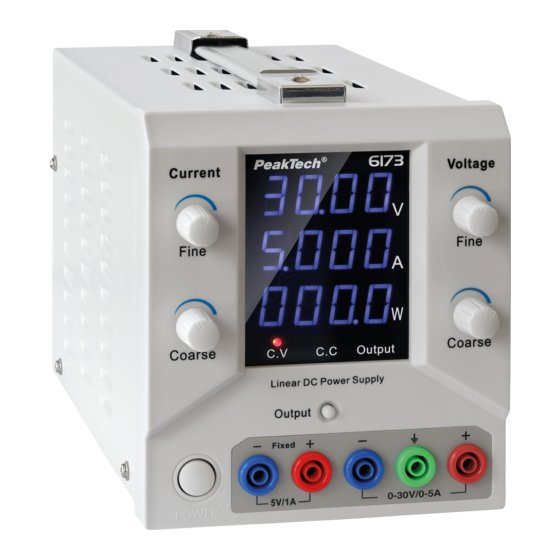
3. Technische Daten Modellnummer: P 6170 P 6171 P 6172 P 6173 Regelbare DC 0 … 60V 0 … 30V 0 … 60V 0 … 30V Ausgangsspannung: Regebarer DC 0 … 2.5A 0 … 5A 0 … 2.5A 0 … 5A... - Page 6 4. Anzeigen und Bedienelemente an der Vorderseite des Gerätes Drehregler (Fein) für Strombegrenzung: Stellen Sie die Strombegrenzung in 1mA Schritten ein Segmentanzeige für Strom, Spannung und Leistung sowie LEDs für den CV (Constant Voltage), CC (Constant Current) und Output (An / Aus) Drehregler (Grob) für Strombegrenzung: Stellen Sie die Strombegrenzung in 100mA Schritten ein Output- Taste: Drücken Sie diese Taste um die Strom- und Spannungsausgabe an den...
-
Page 7: Bedienung
5. Bedienung 5.1. Einstellen der Ausgangsspannung Verwenden Sie den Grob- und Feindrehgeber für die Spannung (Voltage), um den gewünschten Spannungswert einzustellen. Die Einstellung der Ausgangsspannung kann bei aktivem Ausgang, als auch bei abgeschaltetem Ausgang als Spannungsvorwahl erfolgen. Der obere Drehregler (8) wird zur Feineinstellung in 0,01V (10mV) Schritten genutzt ... - Page 8 6.0 Betrieb über Software 6.1 Treiberinstallation Öffnen Sie den Treiber-Ordner (Driver) für Ihr verwendetes Betriebssystem und starten Sie das Installationsprogramm für den benötigten „CH340“ Seriell-zu-USB Treiber. Verbinden Sie das Gerät nach der Treiberinstallation über das USB Kabel mit Ihrem PC und schalten es ein.
- Page 9 6.2 Software Installation Starten Sie das Software Installationsprogramm und führen Sie die Installation aus. Folgen Sie den Anweisungen des Setup-Programms. 6.3 Starten der Software Starten Sie die installierte Kommunikationssoftware und wählen Sie das korrekte Modell sowie die COM-Port Nummer aus. Klicken Sie danach Bild 1...
- Page 10 Geben Sie nun die gewünschten Ausgangswerte unter „OUTPUT SETTING“ ein (Bild 2) und klicken Sie dann auf „ISET“ zum übernehmen der Stromeinstellung und/oder „VSET“ für die Spannungseinstellung. Zum Aktivieren des Ausgangs klicken Sie auf die Fläche. Die Darstellung der Fläche wechselt nach und der Ausgang ist aktiviert.
- Page 11 Datentabelle: Klicken Sie auf ,um die Datentabelle der gemessenen Datenpunkte anzuzeigen (Bild 5): Bild 5 Datenspeicherung Klicken Sie auf die Taste und vergeben Sie zum Speichern einen Dateinamen für ein Excel- Lesbares Format (Bild 6) Bild 6 Der erfolgreiche Export wird bestätigt (Bild7) Bild 7...
- Page 12 Zeitprogramme Starten Sie die Kommunikationssoftware und wählen Modell/COM-Port Nummer aus. Klicken Sie noch nicht auf die Taste. Geben Sie nun Spannung, Strom und Zeit des gewünschten Programmablaufes in die Tabelle ein. Mit den Tasten „Single“ und „Repeat“ bestimmen Sie, ob das Programm einmalig (Single) ausgeführt, oder fortlaufend (Repeat) wiederholt wird.
- Page 13 Programmierung Das Programm läuft. Zum Stoppen des Programmablaufes klicken Sie auf das Symbol. Das Programm stoppt auf dem letzten Programmschritt. Der Ausgang bleibt aktiviert. Zum Deaktivieren des Ausgangs klicken Sie auf die Fläche. Der Programmablauf wird fortgeführt. Der Ausgang ist deaktiviert.
- Page 14 Letzter Stand bei Drucklegung. Technische Änderungen des Gerätes, welche dem Fortschritt dienen, vorbehalten. Druckfehler und Irrtümer vorbehalten. Hiermit bestätigen wir, dass alle Geräte, die in unseren Unterlagen genannten Spezifikationen erfüllen und werkseitig kalibriert geliefert werden. Eine Wiederholung der Kalibrierung nach Ablauf von einem Jahr wird empfohlen. ® © PeakTech...
- Page 15 1. Safety Precautions This product meets the requirements of the following European Union directives for CE conformity: 2014/30/EU (electromagnetic compatibility), 2014/35/EU (low voltage), 2011/65/EU (RoHS). To ensure the operational safety of the appliances and to avoid serious injuries due to current or voltage flashovers or short circuits, the following safety instructions must be observed when operating the appliances.
- Page 16 Measuring environment: These devices are only suitable for use in dry indoor areas and have no protection against dripping or splashing water. These devices are only suitable for use in dust-free indoor areas and use a fan for active ventilation and ventilation slots for cooling the interior.
- Page 17 2. Introduction This series of precise DC laboratory power supplies has a variety of useful functions, such as the presetting of voltage and current limiting values when the output is switched off, the power display in watts or the coarse and fine control of the output values. This series consists of linear-regulated and stabilized power supply units with a safety transformer for outputting a safety extra-low voltage.
-
Page 18: Technical Data
3. Technical data Model number: P 6170 P 6171 P 6172 P 6173 Adjustable DC 0 ... 60V 0 ... 30V 0 ... 60V 0 ... 30V Output voltage: Rechargeable DC 0 ... 2.5A 0 ... 5A 0 ... 2.5A 0 ... - Page 19 4. Displays and controls on the front panel Rotary control (fine) for current limitation: Set the current limitation in 1mA steps Segment display for current, voltage and power as well as LEDs for CV (constant voltage), CC (constant current) and output (on/off) Rotary control (coarse) for current limitation: Set the current limitation in 100mA steps Output button: Press this button to switch the current and voltage output at the 4mm safety sockets (6) on or off...
-
Page 20: Operation
5. Operation 5.1 Setting the output voltage Use the coarse and fine rotary encoder for the voltage to set the desired voltage value. The output voltage can be set as a voltage preselection when the output is active or switched off. ... - Page 21 6.0 Operation via software 6.1 Driver installation Open the driver folder for the operating system you are using and start the installation program for the required "CH340" serial-to-USB driver. After installing the driver, connect the device to your PC via the USB cable and switch it on. Now check the COM port number of the device in the "Windows Device Manager"...
- Page 22 6.2 Software installation Start the software installation program and carry out the installation. Follow the instructions of the setup program. 6.3 Starting the software Start the installed communication software and select the correct model and COM port number. Then click Picture 1...
- Page 23 Now enter the desired output values under "OUTPUT SETTING" (Fig. 2) and then click on "ISET" to accept the current setting and/or "VSET" for the voltage setting. To activate the output, click on the area. The display of the area changes to and the output is activated.
- Page 24 Data table: Click on to display the data table of the measured data points (Fig. 5): Picture 5 Data storage Click on the button and assign a file name for an Excel-readable format to save (Fig. 6) Picture 6 The successful export is confirmed (Fig. 7) Picture 7...
- Page 25 Timed Programs Start the communication software and select the model/COM port number. Do not click on the button yet. Now enter the voltage, current and time of the desired program sequence in the table. Use the "Single" and "Repeat" buttons to determine whether the program is executed once (Single) or repeated continuously (Repeat).
- Page 26 Programming The program is running. To stop the program sequence, click on the symbol. The program stops at the last program step. The output remains activated. To deactivate the output, click on the area. The program sequence is continued. The output is deactivated.
- Page 27 This manual considers the latest technical knowing. Technical changing’s which are in the interest of progress reserved. We herewith confirm, that the units are calibrated by the factory according to the specifications as per the technical specifications. We recommend to calibrate the unit again, after one year. ® © PeakTech 11/2023 Ehr.
- Page 28 PeakTech Prüf- und Messtechnik GmbH – Gerstenstieg 4 - DE-22926 Ahrensburg / Germany +49-(0) 4102-97398 80 +49-(0) 4102-97398 99 info@peaktech.de www.peaktech.de...
Need help?
Do you have a question about the 6170 and is the answer not in the manual?
Questions and answers