Table of Contents
Advertisement
Quick Links
Advertisement
Table of Contents

Related Manuals for PeakTech 6181


Summary of Contents for PeakTech 6181
- Page 1 PeakTech® 6181 Operation manual Programmable linear laboratory power supply...
-
Page 2: Table Of Contents
Table of contents Topic Page Safety instructions for operating the device Introduction Quick start 3.1. Front/rear panel and user interface 3.1.1. Front 3.1.2. Back 3.1.3. User interface 3.2. General inspection 3.3. Switch-on control 3.4. Output control 3.4.1. Voltage output test 3.4.2. -
Page 3: Safety Instructions For Operating The Device
1. safety instructions for operating the device This product complies with the requirements of the following European Union Directives for CE conformity: 2014/30/EU (Electromagnetic Compatibility), 2014/35/EU (Low Voltage), 2011/65/EU (RoHS). To ensure the operational safety of the device and to avoid serious injuries due to current or voltage flashovers or short circuits, the following safety instructions for operating the device must be observed. -
Page 4: Introduction
2. introduction The innovative PeakTech 6181 power supply with color TFT display combines the advantages of a linear-controlled laboratory power supply with the remote control options that were previously mostly reserved for switching power supplies. Operation is via the graphical menu navigation and enables uncomplicated control and programming of the many functions. -
Page 5: Quick Start
3. quick start The following chapter includes: Overview of the front and back User interface overview Initial test of the power supply unit Checking the power supply functions Checking compliance with the initial values Description of the four working modes ... -
Page 6: Front/Rear Panel And User Interface
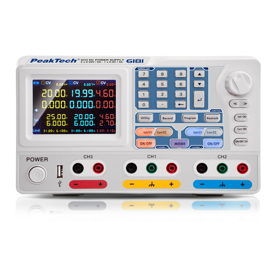
3.1 Front/rear panel and user interface 3.1.1. front side Picture: Front panel of the PeakTech 6180 ① Display ② Number field Parameter input. Number keys, decimal point and reset key included. Up" and "Down" ③ Selection menu or parameter change... -
Page 7: Back
Explanation of the keypad display ON/OFF button Key lights up when the channel has been activated Volt/CV button Key lights up when the channel is in constant voltage mode Curr/CC key Button lights up when the channel is in constant current mode 3.1.2. -
Page 8: User Interface
3.1.3 User interface When the output mode is in independent output mode or channel tracking mode, there are two display modes: three-channel mode (CH1 & CH2 & CH3), two-channel mode (CH1 & CH2). Press the Mode button to switch between modes. Three channel mode Image: User interface in three-channel mode Two- channel mode... -
Page 9: General Inspection
2. check the accessories The supplied accessories are described in "Appendix A:" of this manual. Please Make sure all listed accessories are present and undamaged, if problems are found please contact your dealer or PeakTech directly. 3. check the device If there is physical damage, operational error or a performance problem, please contact your dealer or directly to PeakTech. -
Page 10: Current Output Test
(2) Turn on the channel output and make sure the channel is in constant voltage (CV) mode. (3) Set various voltage values on this channel; Check if the actual voltage value is displayed and also the actual current value is displayed as near zero. (4) Check that the output voltage can be set from zero to the maximum rated voltage. -
Page 11: Overvoltage And Overcurrent Protection
Set output voltage for CH3 Press the Volt CH3 key and the first digit of the CH3 voltage display flashes. Carry out the settings as also described for channel CH1. Set output current for CH1 Press the orange Curr/CC key and the first digit of the CH1 current display flashes. Two input options are available: Change: Turn the knob to change the value of the highlighted digit. -
Page 12: Set Overcurrent Protection Value
Two input options are available: Change: Turn the knob to change the value of the highlighted digit. The < / > keys move the cursor by one digit. Input: Use the number keys to enter the desired value. The old value will be overwritten. ... -
Page 13: Programmable Output
4.4 Programmable output The programmable output function can preset up to 100 groups of timing parameters. When you turn on the programmable output, the instrument outputs the preset voltage and current in the preset time duration. 4.4.1 Data view Press the Program key. The Data View menu is selected (1) The Memory submenu is active. -
Page 14: Data Process
4.4.3 Data Process Press the Program key and turn the knob to switch to the Data Process menu. You can set the parameters of CH1 and CH2 including voltage, current and output time. This function allows 100 parameter groups for each channel. Edit: (1) The Edit submenu is active and shows a short overview of the function keys. -
Page 15: Save Settings And Auto Record
4.4.4 Switching the programmable output on and off In the Data Processing menu: Independent Mode (Normal) Press the orange ON/OFF button to turn the programmable output of CH1 on and off. Press the blue ON/OFF button to turn the programmable output of CH2 on and off. ... -
Page 16: Auto Record
(4) Use the ▼ key and select the Recall submenu. Press the key and a red box will be displayed around the saved setting. Press the ▲ / ▼ keys to change the line or < / > to change the page. Select the desired value, key to access the record. -
Page 17: Output Mode
Graph display Table display (4) Use the ▼ key to switch to the Clear submenu. Press the key to clear the measured values. 4.6 Output mode The output mode can simplify the parameter input of CH1 and CH2. The output mode setting applies to CH1 and CH2 only, without affecting CH3. - Page 18 The connection method of parallel connection of CH1 and CH2 is as in the Figure described below: Series Track (Serial Mode) If CH1 and CH2 are serially connected, you can select this mode to simplify parameter input. You only need to set the parameters of the combined channel.
- Page 19 The connection method of the serial circuit of CH1 and CH2 is as shown in the Figure described below: Channel Track (Dependent Mode) In independent output mode, set the output parameters of CH1 and CH2 and switch to Channel Track mode. When the parameters of one channel are changed, the other channel changes proportionally.
-
Page 20: Utility (System) Settings
4.8.2 Default settings Press the Utility key , then the knob to switch to the Default submenu. Press and the default settings will be accessed. See the following table of PeakTech 6181 default settings. Output Volt Power Output- 12.00V... -
Page 21: Update
Output mode Independent mode Brightness 50 % Summer Baud 115200 Data Bits Utility Serial Odd-Even None Stop Bits Port IP address 192.168.001.099 Subnet Mask 255.255.255.000 LAN Settings Gateway 192.168.001.001 Port 3000 Save Location Internal Settings Stores Location Internal Record Interval Points 1000 Record... -
Page 22: Lan Interface
4.9.2 LAN interface Press the Utility key and turn the knob until you are in the Port Set menu. The Serial menu is active. Use the ▼ key to activate the LAN Set submenu. (1) Press the button to start the edit mode. Set the value of IP address, Subnet Mask, Gateway and Port number. Enter numerical values via the number field and press the keys <... -
Page 23: Troubleshooting
Switch the device back on after performing the above actions. If the problem still exists, contact PeakTech Service. 2. Initial values behave in an unusual way: Check whether the voltage has been set to 0V. If so, change the voltage value. -
Page 24: Technical Specifications
6. technical specifications The following data is based on a device that has been switched on for at least 30 minutes under the specified ambient conditions. Channel 1/Channel 2 Channel 3 0 … 30V Normal/Parallel 0 … 6V Voltage 0 … 60V Serial DC output specifications Normal /Serial... -
Page 25: Appendix
7. appendix Appendix A: Accessories Standard accessories: Power cord with the power plug intended for your country USB data cable CD with "Digit Power Software" and operating instructions Appendix B: Maintenance and cleaning General maintenance Do not store or use the device in direct sunlight for long periods of time. Caution: To avoid damage to the device, do not expose it to sprays, liquids or solvents. - Page 26 We hereby confirm that all devices meet the specifications stated in our documents and are supplied calibrated at the factory. A repetition of the calibration after 1 year is recommended. © PeakTech® 09-2021 Ehr. PeakTech Prüf- und Messtechnik GmbH - Gerstenstieg 4 - DE-22926 Ahrensburg / Germany +49 (0) 4102 97398-80 +49 (0) 4102 97398-99 info@peaktech.de www.peaktech.de...
Need help?
Do you have a question about the 6181 and is the answer not in the manual?
Questions and answers