Advertisement
Quick Links
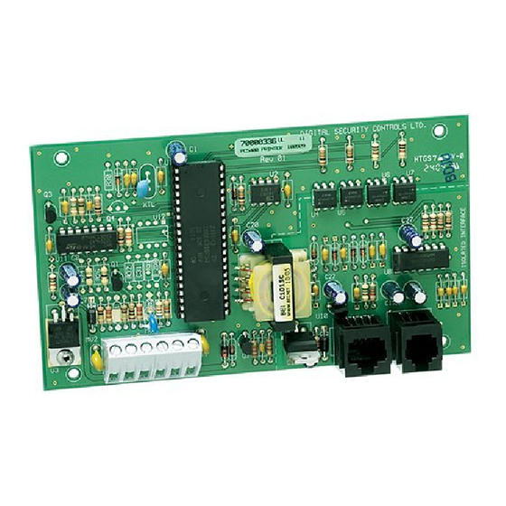
PC5400
Printer Module v3.0TAFNZ
INSTALLATION INSTRUCTIONS
INSTALLATION INSTRUCTIONS
INSTALLATION INSTRUCTIONS
INSTALLATION INSTRUCTIONS
INSTALLATION INSTRUCTIONS
Introduction
Features
Allows compatible control panels to be connected
to a local serial printer.
Module Specifications
• 4-wire (QUAD) hook-up to keybus
• Normal current draw of 35mA
• Tamper and Trouble reporting codes
• Maximum cable length: 200 feet (61 meters)
PC5400 connected to a serial printer
• True RS-232 technology
• DTR protocal
• Four baud rates: 300, 1200, 2400 or 4800
Compatible Products
• PC580
• PC1555
• PC1575
• PC5010
• PC5015
• PC5020
Please refer to the System Installation Manual for information on limitations regarding product
use and function and information on the limitations as to liability of the manufacturer.
Installation
Mounting the Cabinet
When mounting a new cabinet for the PC5400,
select a dry location close to where the serial
printer will be located.
To mount the PC5400:
1. Press the four white circuit board stand-offs
2. Hold the cabinet in position and pull the wires
3. Mount the cabinet securely to the wall using
4. With the cabinet mounted press the PC5400
Wiring
Refer to the Hook-up Diagram included in this
manual.
RED, BLK, YEL and GRN Terminals
Connect the RED, BLK, YEL and GRN terminals to
the RED, BLK, YEL and GRN terminals on the
control panel. Refer to the control panel
Installation Manual for complete instructions on
keybus wiring.
T1 and T2
Connect T1 and T2 to a normally closed switch
that will be used to monitor tampers. If no tamper
switch is desired place a wire between T1 and T2.
• W A R N I N G •
into the raised mounting holes from the back
of the cabinet.
into the cabinet.
the mounting screws provided. Use the
appropriate wall anchors when securing the
panel to the drywall, plaster, concrete, brick or
other similar surfaces.
module into the stand-offs.
Advertisement

Related Manuals for DSC PC5400


Summary of Contents for DSC PC5400
- Page 1 INSTALLATION INSTRUCTIONS Introduction Installation Features Mounting the Cabinet When mounting a new cabinet for the PC5400, Allows compatible control panels to be connected select a dry location close to where the serial to a local serial printer. printer will be located.
- Page 2 PC5400 Hookup Diagram Not Used...
- Page 3 PC5400 Programming If you will be connecting the PC5400 to a PC580, Section [01], Options [4] to [7] ... Baud Rate PC1555, PC1575, PC5010, PC5015 or PC5020 Program the baud rate the PC5400 module will use to communicate with the serial printer. The...
- Page 4 FCC useful: “How to Identify and Resolve Radio/Television Interference Problems”. This booklet is available from the U.S. Government Printing Office, Washington D.C. 20402, Stock # 004-000-00345-4. © 2000 Digital Security Controls Ltd. Toronto, Canada 1-8OO-387-363O • www.dsc.com Printed in Canada 29005747 R001...
Need help?
Do you have a question about the PC5400 and is the answer not in the manual?
Questions and answers