Table of Contents
Advertisement
Quick Links
Advertisement
Table of Contents

Summary of Contents for DSC MAXSYS PC4850
- Page 1 ® PC4850 v1.0 • Installation Manual WARNING: This manual contains information on limitations regarding product use and function and information on the limitations as to liability of the manufacturer. The entire manual should be carefully read.
- Page 2 It is ranty: (i) freight cost to the repair centre; (ii) products which are not identified with DSC's product important that all system users be trained in the correct operation of the alarm system and that they know label and lot number or serial number;...
-
Page 3: Table Of Contents
Ta ble of Contents Section 1:Introduction 3.2 Programming PC4850 From a Keypad ......5 1.1 About PC4850 Manuals ............1 3.3 Programming From DLS-3 ..........5 1.2 Features .................1 3.4 Enrolling the PC4850 ............5 1.3 Specifications ................1 3.5 Programming Users’ Names, 1.4 Additional Devices ..............1 Telephone Numbers, and Codes ........6 3.6 Programming the Greeting Display ........7 Section 2:Installing &... - Page 4 Transformer 16.0V @ 40 VA For EU countries, the power supply must meet the applicable requirements of the Low Voltage Directive NOTE: Do not connect transformer to a receptacle controlled by a switch, for UL/ULC installations. Ground wire from building 16 V 40VA min.
-
Page 5: Section 1:Introduction
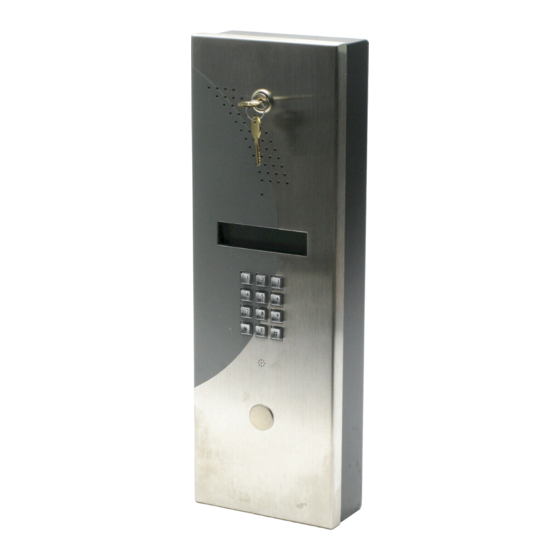
Section 1: Introduction The PC4850 Telephone Entry Module connects to PC4020 1.3 Specifications v3.2 and higher systems to provide access control and • Connects to PC4020 panel with 4-wire Combus communication to tenants of condominiums, offices, or • AC input - 16V , 40VA apartment buildings. -
Page 6: Section 2:Installing & Wiring Pc4850
Section 2: Installing & Wiring PC4850 2.1 Unpacking the PC4850 3. Use a screwdriver to lift the prongs on the postal lock hole plug, and remove the plug from the hole. Check that the following parts are in your PC4850 package: •... -
Page 7: Connecting Magnetic Locks
2.9 Connecting the Combus DC (Silent) Door Strikes If you will be connecting DC door strikes, follow the dia- The Combus is used by the Maxsys control panel and the gram below: modules to communicate with each other. The four Com- bus terminals of the main panel must be connected to the Use AWG#18 four Combus terminals or wires of all modules. -
Page 8: Connecting The Pc4850 To Ground
2.12 Connecting the PC4850 to Ground 2.14 Lithium Batteries Make a ground connection as shown below: There is a lithium battery on the module. Do not attempt to replace this battery. There is a danger of explosion if the battery is incorrectly replaced. If the lithium battery stops working, return the circuit board to the supplier. -
Page 9: Section 3:Programming The Pc4850
Section 3: Programming the PC4850 This section describes how the PC4850 modules works, and how to program it. You can program the PC4850 using either of these methods: • using a Maxsys system keypad • using DLS-3 and a computer (see section 3.3, “Programming From DLS-3”, and the DLS-3 manual). 3.1 How the PC4850 Works Door Unlocked, When the PC4850 is set up and running correctly, visitors... -
Page 10: Programming Users' Names, Telephone Numbers, And Codes
3.5 Programming Users’ Names, Telephone 1. From the Program Code menu, use the right arrow (>) key to scroll to the following display: Numbers, and Codes Select (2) < > To get the PC4850 up and running, you, or the building staff, will need to program up to four items of informa- Edit User Name tion for each user:... -
Page 11: Programming The Greeting Display
2. Press [5] or [*]. NOTE: We recommend that users who have different 3. Enter up to 12 digits for the telephone number. If you telephone numbers be given different tenant codes. If are using the No Bill option, program the 3-digit tele- you program more than one user with the same ten- phone line number provided by your telephone com- ant code, the PC4850 will only call the user who is first... -
Page 12: Changing The Battery Supervision Option
3.11 Setting up Access Codes for Two Building 1. Enter [*][8][Installer Code]. 2. Enter reference number [0017XX00], where XX is the Entry Points number of the PC4850 module. Ref #: [0017XX02], where XX = PC4850 module number 3. Use the arrow (<>) keys to scroll until the display The PC4850 can control two entry points (e.g., a door and shows: a car gate) using the door strike and the auxiliary relay... -
Page 13: Section 4:Testing And Troubleshooting
Section 4: Testing and Troubleshooting 4.1 Testing the PC4850 Once the PC4850 is connected and programmed, test each of its functions to make sure it is working correctly. The PC4850 should work as described in section 3.1, “How the PC4850 Works”. 4.2 Troubleshooting The PC4850 should work correctly without the need for adjustments. -
Page 14: Section 5:Programming Worksheet
Door Time: 010 seconds I_____I_____I_____I Aux Rly Time: 000 seconds I_____I_____I_____I Call Time: 060 seconds I_____I_____I_____I 5.3 Entry Access Divider Default: [9999] Valid entries are 0000 to 9999. I_____I_____I_____I_____I 5.4 Greeting Display Default: [DSC Ltd. MAXSYS] Greeting Display: I_____I_____I_____I_____I_____I_____I_____I_____I_____I_____I_____I_____I_____I_____I_____I_____I I_____I_____I_____I_____I_____I_____I_____I_____I_____I_____I_____I_____I_____I_____I_____I_____I... -
Page 15: Tenant Information Record Sheet
Tenant Information Record Sheet NOTE: Make copies of this sheet for building staff to record tenant information. User Name Telephone Number Tenant Code Access Code I_____I_____I_____I_____I_____I_____I_____I_____I_____I_____I_____I_____I_____I_____I_____I_____I I_____I_____I_____I_____I_____I_____I_____I_____I_____I_____I_____I_____I I_____I_____I_____I_____I I_____I_____I_____I_____I_____I_____I I_____I_____I_____I_____I_____I_____I_____I_____I_____I_____I_____I_____I_____I_____I_____I_____I I_____I_____I_____I_____I_____I_____I_____I_____I_____I_____I_____I_____I I_____I_____I_____I_____I I_____I_____I_____I_____I_____I_____I I_____I_____I_____I_____I_____I_____I_____I_____I_____I_____I_____I_____I_____I_____I_____I_____I I_____I_____I_____I_____I_____I_____I_____I_____I_____I_____I_____I_____I I_____I_____I_____I_____I I_____I_____I_____I_____I_____I_____I I_____I_____I_____I_____I_____I_____I_____I_____I_____I_____I_____I_____I_____I_____I_____I_____I I_____I_____I_____I_____I_____I_____I_____I_____I_____I_____I_____I_____I I_____I_____I_____I_____I I_____I_____I_____I_____I_____I_____I I_____I_____I_____I_____I_____I_____I_____I_____I_____I_____I_____I_____I_____I_____I_____I_____I I_____I_____I_____I_____I_____I_____I_____I_____I_____I_____I_____I_____I... - Page 16 The Ringer Equivalence number of this unit is 0.1. Indice d’équivalence de la sonnerie de ce produit est 0.1. Direct all comments concerning this ©2002 Digital Security Controls Ltd. publication to pubs@dscltd.com. Technical Support: 1-800-387-3630 Toronto, Canada • www.dsc.com Printed in Canada 29005231 R004...


Need help?
Do you have a question about the MAXSYS PC4850 and is the answer not in the manual?
Questions and answers