
Related Manuals for Ruijie Reyee AirMetro550G-B


Summary of Contents for Ruijie Reyee AirMetro550G-B
- Page 1 Ruijie Reyee RG- AirMetro550G-B Wireless Bridge Installation Guide Document Version: V1.3 Date: 2024-06-03 Copyright © 2024 Ruijie Networks...
- Page 2 All rights are reserved in this document and this statement. Any reproduction, excerption, backup, modification, transmission, translation or commercial use of this document or any portion of this document, in any form or by any means, without the prior written consent of Ruijie Networks is prohibited.
-
Page 3: Preface
Preface Audience This document is intended for: Network engineers Technical support and servicing engineers Network administrators Technical Support Official Website of Ruijie Reyee: https://reyee.ruijie.com Technical Support Website: https://reyee.ruijie.com/en-global/support Case Portal: https://www.ruijienetworks.com/support/caseportal Community: https://community.ruijienetworks.com ... - Page 4 Note An alert that contains additional or supplementary information that if not understood or followed will not lead to serious consequences. Specification An alert that contains a description of product or version support. Note This document provides the installation steps, troubleshooting, technical specifications, as well as the specifications and use guidelines of cables and connectors.
-
Page 5: Table Of Contents
Contents Preface ..............................I 1 Product Introduction .......................... 1 1.1 Overview ............................ 1 1.2 Package Contents........................1 1.3 Appearance ..........................1 1.3.1 Appearance ........................1 1.3.2 Ports, Buttons and LEDs ....................3 1.4 Technical Specifications ......................4 1.5 Power Supply Technical Specifications ..................6 2 Preparing for Installation ........................ - Page 6 3.2 Before You Begin ........................12 3.3 Safety Precautions During Installation ..................12 3.4 Installation Procedures ......................13 3.4.1 Installing the Wireless Bridge ..................13 3.4.2 Removing the Wireless Bridge ..................15 3.4.3 Installing the Antenna....................17 3.5 Connecting Cables........................24 3.6 Verifying the Installation ......................
-
Page 7: Product Introduction
Product Introduction Overview The RG-AirMetro550G-B wireless bridge is launched by Ruijie Reyee. It utilizes the IEEE 802.11ac standard for efficient and reliable communication. Operating in the 5 GHz band and supporting 2x2 MIMO technology, this product delivers a maximum wireless rate of 867 Mbps for bridging, ensuring more than sufficient bandwidth for delivering point to point (PTP) and point to multi-point (PTMP) services. - Page 8 Hardware Installation and Reference Guide Product Introduction Back view...
-
Page 9: Ports, Buttons And Leds
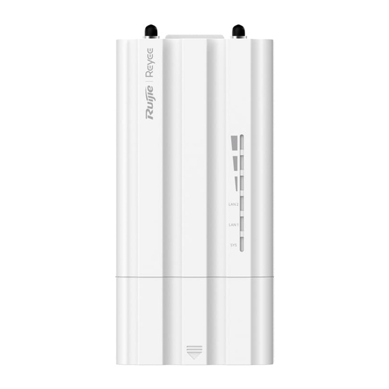
Hardware Installation and Reference Guide Product Introduction Note The label is located on the back of the device. 1.3.2 Ports, Buttons and LEDs Figure 1-2 Ports, Buttons and LEDs of the RG-AirMetro550G-B Wireless Bridge Table 1-2 Ports, Buttons and LEDs of the RG-AirMetro550G-B Wireless Bridge Mark Item Description... -
Page 10: Technical Specifications
Hardware Installation and Reference Guide Product Introduction Table 1-3 LEDs Status Description System LED Solid green The device is operating normally. Blinking Fast blinking (8 to 10 times/second): The device is starting up. Fast blinking (2 times/second): The device is initializing. Fast blinking (2 times/second): The device is upgrading. - Page 11 Hardware Installation and Reference Guide Product Introduction European Union & United Kingdom: 2400-2483.5 MHz, EIRP ≤ 20 dBm 5470- 5725 MHz, EIRP ≤ 30 dBm Myanmar: 2400-2483.5 MHz, EIRP ≤ 23 dBm 5725-5825 MHz, EIRP ≤ 30 dBm Thailand: 2.4 GHz to 2.4835 GHz: 20 dBm 5.725 GHz to 5.825 GHz: 30 dBm Indonesia: 2400-2483.5 MHz, EIRP ≤...
-
Page 12: Power Supply Technical Specifications
Hardware Installation and Reference Guide Product Introduction Operating humidity: 5% to 95% RH (non-condensing) Storage humidity: 5% to 95% RH (non-condensing) Installation Directly mounted onto an antenna IP Rating IP55 Flame Rating UL94V-0 Certification MTBF > 400000 hrs Warning Operation of this equipment in a residential environment could cause radio interference. Note The weight in the above table indicates the net weight of a single unit. - Page 13 Hardware Installation and Reference Guide Product Introduction (2) RJ45 PoE port: Pins 1, 2, 3, 4, 5, 6, 7 and 8 are for data transmission, with positive on pins 4 and 5 and negative on pins 7 and 8. Technical specifications of the DC adapter: Inner Diameter Outer Diameter...
-
Page 14: Preparing For Installation
Hardware Installation and Reference Guide Preparing for Installation Preparing for Installation Safety Precautions Note To prevent device damage and physical injury, please read carefully the safety precautions described in this chapter. The following safety precautions do not cover all possible dangers. 2.1.1 General Safety Precautions ... -
Page 15: Installation Environment Requirements
Hardware Installation and Reference Guide Preparing for Installation Installation Environment Requirements To ensure normal operation and a prolonged service life of the device, the installation site must meet the following requirements. 2.2.1 Environment Install the device in a well-ventilated environment. If it is installed in a closed room, make sure there is a good cooling system. -
Page 16: Surge Protection
Hardware Installation and Reference Guide Preparing for Installation Distance Between Base Station Recommended Installation Bridge Type and Customer Premises Height (Above the Obstacle) Equipment (CPE) 500 m (1640.42 ft.) 4 m (13.12 ft.) 2.2.2 Surge Protection When the connection cable between the main grounding conductor and local equipotential earthing terminal board (LEB) on each floor is short, use a stranded copper wire with a sectional area not less than 1.318 mm2 (16 AWG) for the connection cable. -
Page 17: Tools
Hardware Installation and Reference Guide Preparing for Installation Tools Table 2-2 Tools Common Marker, Phillips screwdriver, hammer drill, power cords, Ethernet cables, and diagonal plier Tools Anti-ESD gloves, wire stripper, crimping plier, RJ45 crimping plier, wire cutter, and Special Tools waterproof adhesive tape Meters Multimeter... -
Page 18: Installation
Hardware Installation and Reference Guide Installation Installation Caution Before installing the device, make sure that you have carefully read the requirements described in Chapter 2. Installation Procedure Before You Begin Carefully plan and arrange the installation location, networking mode, power supply, and cabling of the device before installation. -
Page 19: Installation Procedures
Hardware Installation and Reference Guide Installation wireless bridge. Ensure that the horizontal angle formed by the two wireless bridges is greater than 120 degrees. The specific installation location of the wireless bridge should be determined by professionals after conducting a thorough site survey. Before installation, ensure that the installation location meets the requirements in 2.2.1 , and pay attention to the... - Page 20 Hardware Installation and Reference Guide Installation (3) Connect the SMA connector of the wireless bridge to that of the antenna. (4) Install the protective cover.
-
Page 21: Removing The Wireless Bridge
Hardware Installation and Reference Guide Installation 3.4.2 Removing the Wireless Bridge (1) Remove the protective cover by pulling it upward. (2) Unscrew the RF cable. - Page 22 Hardware Installation and Reference Guide Installation (3) Remove the wireless bridge by pulling it upward and then outward. (4) Remove the RF cable.
-
Page 23: Installing The Antenna
Installation 3.4.3 Installing the Antenna Note You are advised to use the following three Ruijie antenna models: RG-ANT20S-90, RG-ANT16S-120, and RG- ANT13-360. Installing a 90° antenna (1) Secure the upper and lower brackets to the antenna with four screws, two for each bracket. - Page 24 Hardware Installation and Reference Guide Installation (3) Secure the antenna to the pole. Note M8 x 150 mm screws are recommended.
- Page 25 Hardware Installation and Reference Guide Installation (4) The installation is complete.
- Page 26 Hardware Installation and Reference Guide Installation Installing a 120° antenna (1) Secure the mounting bracket to the antenna with four screws.
- Page 27 Hardware Installation and Reference Guide Installation (2) Attach the bracket holder to the bracket with two screws. (3) Secure the antenna to the pole. Note M8 x 150 mm screws are recommended.
- Page 28 Hardware Installation and Reference Guide Installation Installing a 360° antenna (1) Secure the antenna to the pole. Note M8 x 150 mm screws are recommended.
- Page 29 Hardware Installation and Reference Guide Installation (2) The installation is complete.
-
Page 30: Connecting Cables
Hardware Installation and Reference Guide Installation Connecting Cables (1) Use or make an Ethernet cable based on the distance between the wireless bridge and the power source. The device supports PoE power supply over Cat5e or better cables with a cable length up to 100 meters (328 ft.). -
Page 31: Debugging
Hardware Installation and Reference Guide Debugging Debugging Setting Up the Configuration Environment Before setting up the configuration environment using the 24 V, 0.5 A PoE power supply or the 12 V DC power supply, verify that the power cord is properly connected and that the configuration environment meets safety requirements. -
Page 32: Monitoring And Maintenance
Monitoring and Maintenance Hardware Installation and Reference Guide Monitoring and Maintenance Monitoring You can observe the LED status to monitor the device in operation. Hardware Maintenance If the hardware is faulty, please contact Ruijie Networks technical support for assistance. -
Page 33: Common Troubleshooting
Hardware Installation and Reference Guide Common Troubleshooting Common Troubleshooting Troubleshooting Flowchart... -
Page 34: Appendix
Hardware Installation and Reference Guide Appendix Appendix Connectors and Media 1000BASE-T/100BASE-TX/10BASE-T Port The 1000BASE-T/100BASE-TX/10BASE-T port is a 10/100/1000 Mbps auto-negotiation port that supports auto MDI/MDIX Crossover. Compliant with IEEE 802.3ab, the 1000BASE-T port requires Category 5e 100-ohm UTP or STP (recommended) with a maximum distance of 100 meters (328 feet). - Page 35 Hardware Installation and Reference Guide Appendix The following figure shows feasible connections of the straight-through and crossover twisted pair cables for a 100BASE-TX/10BASE-T port. Figure 7-2 100BASE-TX/10BASE-T Twisted Pair Connections St raight -Through Cr ossover Switch Adapter Switch Switch...
Need help?
Do you have a question about the Reyee AirMetro550G-B and is the answer not in the manual?
Questions and answers