
Related Manuals for Rhythm Healthcare H9200FF


Summary of Contents for Rhythm Healthcare H9200FF
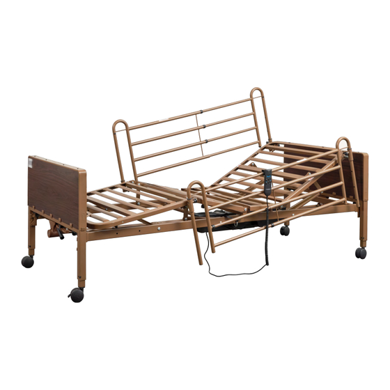
- Page 1 ITEMS: H9200FF: (Semi-Electric Bed w/ Full Side Rails) H9200FH: (Semi-Electric Bed w/ Half Side Rails) SEMI-ELECTRIC HOMECARE BED WEIGHT CAPACITY 450 LBS PICTURED: SEMI ELECTRIC BED WITH FULL SIDE RAILS...
-
Page 2: Table Of Contents
TABLE OF CONTENTS SPECIAL NOTES SAFETY INSTRUCTIONS 4, 5 ASSEMBLY INSTRUCTION ASSEMBLY - MOTOR INSTALLATION ASSEMBLY - BED RAIL INSTALLATION OPTIONAL FIXED HEIGHT ADJUSTMENT OPTIONAL STORAGE EQUIPMENT OPERATION AND ADJUSTMENT USING PENDANT MAINTENANCE & SAFETY CHECKS WARRANTY MEASUREMENTS WARNINGS 21-25... -
Page 3: Special Notes
SPECIAL NOTES WARNINGS/CAUTION notices used in this manual apply to hazards or unsafe practices which could result in personal injury and/or property damage. The information contained in this document is subject to change without notice. Check all parts for shipping damage and test before using. In case of damage, do NOT use. Contact your provider for further instruction. -
Page 4: Safety Instructions
Replacement mattresses and bed rails with dimensions different than the original equipment supplied or specified by Rhythm Healthcare may not be interchangeable. Variations in side rail design and thickness or density of the mattress could cause entrapment. Use ONLY distributed Rhythm Healthcare replacement parts. - Page 5 DO NOT, under any circumstances, cut or remove the round grounding prong from any plug used with or for Rhythm Healthcare products. In addition, Rhythm has placed red WARNING tags on some equipment. DO NOT remove these tags.
-
Page 6: Assembly Instruction
ASSEMBLY INSTRUCTIONS *Set-up and Assembly is for Dealers/Providers Only* These procedures must be performed by a qualified technician only. 1. CONFIRM THAT ALL PARTS ARE PRESENT: A. Foot Deck Section B. Head Deck Section C. Headboard & Foot board D. Casters (4)- 2 locking, 2 non-locking E. - Page 7 ASSEMBLY INSTRUCTIONS - CONTINUED 2. Place both ends of the frame/sleep surface on their side and align the flange with the receptacle as shown.
- Page 8 ASSEMBLY INSTRUCTIONS - CONTINUED 3. To attach the head and foot sections, slide the two sides together and lock into position with cotter pin and clasp. To disassemble the head and foot section, remove cotter pin and clasp and separate sections.
- Page 9 ASSEMBLY INSTRUCTIONS - CONTINUED 4. Secure the frame/sleep surface with the cotter pin as shown (Figure A). Lock the cotter pin with the attached clasp. Repeat on the opposite side (Figure B). Figure A Figure B...
- Page 10 ASSEMBLY INSTRUCTIONS - CONTINUED ATTACHING BED ENDS TO FRAME: 1. Install casters onto bed ends by inserting the stem of the caster into the leg receptacle. It is recommended to install one locking caster and one non-locking caster on each bed end. The locking casters should be installed diagonally from each other.
-
Page 11: Assembly - Motor Installation
ASSEMBLY INSTRUCTIONS - CONTINUED 3. Before installing motor, plug hand pendant and Hi/Low motor cable into motor as shown. 4. Align the motor with the actuator bar and lift the head spring to the highest position. The motor will automatically be pulled towards the bed and lock onto the actuator. -
Page 12: Assembly - Bed Rail Installation
ASSEMBLY INSTRUCTIONS - CONTINUED Attaching Bed Rails NOTE: Half Rails The head section features labels on the frame marked, “Attach Half Rails Here” . NOTE: Full Rails The foot and head section have color coded springs, labels and notches in the frame. Install the cross brace between the black springs for proper rail placement. - Page 13 BED RAIL ASSEMBLY Full Bed Rails: To install Full Bed Rails, lift the head section and find the rail receptacle located on the frame of the bed as shown (Figure A). Pull receptacle outward and return head section to flat position. Turn receptacle in a vertical position to receive the rail (Figure B).
-
Page 14: Optional Fixed Height Adjustment
BED HEIGHT ADJUSTMENT Optional fixed height adjustment with lock pins. NOTE: The four large pins are used if the height of the bed is to be locked at a set height. Set the height of the bed so that the hole in the leg is aligned with the hole in the bed end outer leg. -
Page 15: Optional Storage Equipment
OPTIONAL BED EQUIPMENT Shown on Bed: Storage Transporter with motor attached with storage strap *Optional equipment. Not included. -
Page 16: Operation And Adjustment Using Pendant
OPERATION & ADJUSTMENT USING PENDANT OPERATION AND ADJUSTMENT SEMI ELECTRIC OPERATION The accompanying pictures detail the Semi-Electric beds and will acquaint the user with the bed functions and controls. 1. Operate the bed through all phases of its operation. 2. If any problems arise during the test, recheck all electrical connections and mechanical hookups. Pendant instructions on next page. - Page 17 OPERATION & ADJUSTMENT USING PENDANT SEMI ELECTRIC BED PENDANT RAISE HEAD AND FOOT TOGETHER RAISE FOOT RAISE HEAD LOWER FOOT LOWER HEAD LOWER HEAD AND FOOT TOGETHER...
- Page 18 ADJUSTING BED HEIGHT SEMI-ELECTRIC BEDS SEMI-ELECTRIC BED OPERATION The accompanying pictures detail the semi-electric beds with the hi/lo and foot crank locations where applicable. • The semi-electric single and two crank beds with hi/lo operation use a four function pendant for head and foot spring functions and a hand crank for hi/lo bed operation.
-
Page 19: Maintenance & Safety Checks
• Check all bolts and tighten as needed WARRANTY Original Purchaser. Limited LIfetime on welds, 5 year on frame, motor and pendant. 1 Year on all other parts and components. During the warranty period, Rhythm Healthcare will determine if a defective item will be repaired or replaced. -
Page 20: Measurements
SEMI-ELECTRIC SPECIFICATIONS: Overall dimension 35.63” W x 87.2” L Sleep surface 34.65” W x 79.73” L Mattress: 80” mattress required Lowest height (outer castor setting) 15.35” H Highest height (outer castor setting) 23.25” H Motor: (1) Castor: (2) x 3” castor w/locking and (2) x 3” castor w/o locking Hand Crank &... -
Page 21: Warnings
Healthcare products are specifically designed and manufactured for use in conjunction with Rhythm Healthcare accessories. Accessories designed by other manufacturers have not been tested by Rhythm Healthcare and are not recommended for use with Rhythm Healthcare products. Keep all moving parts, including the main frame, mattress deck (head and foot springs/sections) and all drive shafts free of obstruction (i.e. - Page 22 The initial set up of this bed must be performed by a qualified technician. The total weight limit of the Rhythm Healthcare 36”/91.4 cm wide Electric bed (including accessories, mattress, occupant and any other person/object positioned on the bed) is 450 pounds (204 kg.); 350 pounds (158 kg) patient weight.
- Page 23 Use only authorized Rhythm Healthcare replacement parts and/or accessories otherwise the warranty is voided. Rhythm Healthcare will not be responsible for any damage or injury that may result. To reduce the risk of entrapment, check that the bed rail cross-braces DO NOT exceed the width of the mattress.
- Page 24 BED RAIL WARNINGS Although bed rails are not rated to any specific weight limitation, the bed rails may become deformed or broken if excessive side pressure is exerted on the bed rails. The bed rail is not an assist rail for getting in or out of bed. DO NOT use the bed rails as push handles when moving the bed.
- Page 25 ELECTRICAL WARNINGS - CONTINUED Check that all cables and cords are routed so they will not become entangled or pinched. Otherwise, damage may result. If a liquid is spilled in or around the Electric bed, unplug the Electric bed before cleaning. Clean up the spills and allow the Electric bed to dry thoroughly before using the electric controls again.
- Page 26 Rhythm Healthcare Clearwater, FL 33762 contactus@rhythmhc.com www.rhythmhc.com v2: 10/16/23...
Need help?
Do you have a question about the H9200FF and is the answer not in the manual?
Questions and answers