Sign In
Upload
Manuals
Brands
Digital Monitoring Products Manuals
Control Panel
XR Series
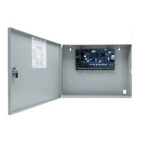
Digital Monitoring Products XR Series Manuals
Manuals and User Guides for Digital Monitoring Products XR Series. We have
2
Digital Monitoring Products XR Series manuals available for free PDF download: Programming Manual, Installation Manual
Digital Monitoring Products XR Series Programming Manual (92 pages)
Brand:
Digital Monitoring Products
| Category:
Control Panel
| Size: 1 MB
Table of Contents
Table of Contents
3
Introduction
9
XR Programming Information
9
Getting Started
9
Quick Reference
9
Accessing the User Menu
10
Begin a Programming Session
10
Encrypted Communications (XR550 with Encryption Only)
10
Programmer Operation
10
Programmer Lockout Codes
11
Reset Timeout
11
Power up
11
Keypads
11
Special Keys
11
Entering Alpha Characters
12
Entering Non-Alpha Characters
12
Keypad Displays Current Programming
13
Multiple Displays
13
Asterisks in Programming
13
Compliance Instructions
13
Initialization
14
Clear All Memory
14
Clear All Codes
14
Clear All Schedules
14
Clear Display Events Memory
14
Clear Zone Information
14
Clear Area Information
14
Clear Output Information
14
Clear Communication and Remote Options
14
Clear Wi-Fi
14
Communication
15
Account Number
15
Transmit Delay
15
Communication Path
15
Communication Type
15
Path Type
15
Test Report
16
Test Frequency
16
Test Day
16
Test Time
16
Check in
16
Fail Time
16
Encryption (XR550 with Encryption Only)
16
IPV6 Address
17
Receiver IP
17
Receiver Port
17
First Telephone Number
17
Second Telephone Number
17
Advanced Programming
17
Apn
17
Fail Test Hours
17
Protocol
17
Retry Seconds
17
Substitution Code
18
Alarm Switch
18
Duplicate Alarms
18
Alarm Reports
18
Supervisory/Trouble Reports
19
Opening/Closing and User Reports
19
Door Access Report
19
Panic Test (Network Only)
19
Send Communication Trouble
20
Send Path Information
20
Network Options
21
Wi-Fi Setup
21
Wps
21
List
21
Manual
21
Test
22
Wireless Security Type
22
Wireless Network Key
22
Ipv6
22
Dhcp
22
Local IP Address
22
Gateway Address
22
Subnet Mask
22
DNS Server
23
Passphrase (XR550 with Encryption Only)
23
734N Listen Port
23
734N Passphrase
23
Device Setup
24
Custom Card Definitions
24
Wiegand Code Length
24
Site Code Position
24
Site Code Length
24
User Code Position
24
User Code Length
24
Require Site Code
24
Site Code Display
25
Number of User Code Digits
25
Device Number
25
Device Name
26
Device Type
26
Private Door
27
1100T
27
Device Communication Type
27
Serial Number
27
Supervision Time
27
Access Areas
27
Egress Areas
28
Display Areas
28
Strike Time
29
Strike Delay
29
Fire Exit Release
29
Public Door
29
Output Group
29
Schedule Override
30
Auto Force Arm Device
30
Door Real-Time Status
30
Send Door Forced Message
30
Program 734/734N Options
30
Activate Zone 2 Bypass
30
Zone 2 Bypass Time
31
Relock on Zone 2 Change
31
Activate Zone 3 Request to Exit
31
Zone 3 REX Strike Time
31
Activate Onboard Speaker
31
Card Options
31
Require Site Code (if Card Format Is Set to DMP)
31
No Communication with Panel
32
Remote Options
33
Remote Key
33
Remote Disarm
33
Armed Answer Rings
33
Disarmed Answer Rings
33
PC Modem
33
Alarm Receiver Authorization
33
Service Receiver Authorization
33
Manufacturer Authorization
34
Allow Network Remote
34
Network Programming Port
34
Encrypt Network Remote
34
Allow Cellular Remote
34
Apn
34
Encrypt Cellular Remote
34
Entré Connection
34
Entré Incoming TCP Port
34
Entré IP Address
34
Entré Backup TCP Port
35
Entré Reports
35
Arm and Disarm Reports
35
Zone Reports
35
User Command Reports
35
Door Access Reports
35
Supervisory Reports
35
Video Reports
35
Entré Checkin
35
Entré Passphrase
35
Integrator Connection
36
Integrator Incoming TCP Port
36
Integrator IP Address
36
Integrator Outbound TCP Port
36
Integrator Backup Connection
36
Integrator Backup TCP Port
36
Integrator Reports
36
Arm and Disarm Reports
36
Zone Reports
36
User Command Reports
36
Supervisory Reports
37
Integrator Passphrase
37
Send Local Changes
37
Remote Change IP
37
Remote Change Port
37
Remote Telephone Number
37
App Key
37
System Reports
38
Abort Report
38
Restoral Reports
38
Bypass Reports
38
Schedule Change Reports
38
Code Change Reports
38
Access Keypads
38
Ambush
38
Late to Open
38
Early to Close
39
Video Reports
39
System Options
40
System
40
Instant Arming
40
Closing Wait
40
Entry Delay 1
40
Cross Zone Time
41
Zone Retard Delay
41
Power Fail Delay
41
Swinger Bypass Trips
41
Reset Swinger Bypass
41
Zone Activity Hours
41
Time Zone Changes
42
Latch Supervisory Zones
42
Programming Menu Language
43
User Menu and Status List Language
43
Bypass Limit
44
House Code
44
Wireless Encryption
44
Enter Passphrase
44
Detect Wireless Jamming
44
Trouble Audible Annunciation
44
Enable Keypad Panic Keys
44
Occupied Premises
44
Enhanced Zone Test
45
Send 16 Character Names
45
Keypad Armed LED
45
Use False Alarm Question
45
Allow Own User Code Change
45
Panic Supervision
46
Weather Zip Code
46
EOL Selection
46
Celsius Temperature Option
46
Bell Options
47
Bell Cutoff Time
47
Automatic Bell Test
47
Bell Output
47
Bell Action
47
Fire Bell Action
47
Burglary Bell Action
47
Supervisory Bell Action
47
Panic Bell Action
47
Emergency Bell Action
47
Output Options
48
Cutoff Output
48
Output Cutoff Time
48
Communication Trouble Output
48
Fire Alarm Output
48
Fire Trouble Output
49
Panic Alarm Output
49
Ambush Output
49
Entry Output
49
Begin Exit Output
49
End Exit Output
49
Ready Output
49
Armed Output
49
Disarmed Output
49
Telephone Trouble Output
49
Late to Close Output
50
Device Fail Output
50
Sensor Reset Output
50
Closing Wait Output
50
Arm-Alarm Output
50
Supervisory Alarm Output
50
Heat Saver Temperature
50
Cool Saver Temperature
50
Carbon Monoxide Alarm Output
51
Lockdown Output Alarm Output
51
Zone Monitor Output
51
Output Information
52
Output Number
52
Output Name
52
Output Real-Time Status
52
Serial Number
52
Supervision Time
52
Trip with Panel Bell Option
52
Output Groups
53
Group Number
53
Group Name
53
Output Number
53
Menu Display
54
Armed Status
54
Time
54
Arm/Disarm
54
Status List
55
Display Keypads
55
System Monitor Troubles
55
Fire Zones
55
Burglary Zones
55
Supervisory Zones
56
Panic Zones
56
Emergency Zones
56
Auxiliary 1 Zones
56
Auxiliary 2 Zones
56
Carbon Monoxide Zones
56
Communication Trouble
56
Pc Log Reports
57
Net IP Address
57
Net Port
57
Arm and Disarm Reports
57
Zone Reports
57
User Command Reports
57
Door Access Reports
57
Supervisory Reports
58
PC Log Real-Time Status
58
Area Information
59
Exit Delay
59
Closing Check
59
Closing Code
59
Any Bypass
59
Area Schedules
60
Early Morning Ambush (XR550 Network Panels Only)
60
Area Number
60
All/Perimeter Programming
60
Home/Sleep/Away Programming
60
Area Name
61
Account Number
61
Opening/Closing Reports
61
Automatic Arming
61
Bad Zones
62
Automatic Disarming
62
Burglary Bell Output
62
Armed Output Number
62
Late Output Number
62
Late Arm Delay
62
Bank Safe & Vault (XR550 with Network or Encryption Only)
62
Common Area
63
Arm First Area
63
Dual Authority (XR550 with Network or Encryption Only)
63
Card Plus Pin
63
Zone Information
64
Zone Number
64
Zone Name
64
Zone Location
65
Zone Type
65
Area Assignment
65
Fire Bell Output
65
Arming Zone Area Assignment
66
Style
66
Expander Serial Number
67
Next Zone
67
Competitor Wireless
67
Two Button
67
Wireless
68
Competitor Wireless Serial Number
68
Serial Number Entry
68
Contact
68
Supervision Time
68
LED Operation
68
Disarm/Disable
68
PIR Pulse Count
68
PIR Sensitivity
69
Pet Immunity
69
Next Zone
69
V-Plex Serial Number Entry
69
Alarm Action
69
Disarmed Open
70
Report to Transmit
70
Output Number
70
Output Action
70
Swinger Bypass
71
Prewarn Keypad Addresses
71
Chime
71
Presignal Keypad Addresses
71
Fast Response
71
Entry Delay
72
Zone Retard Delay
72
Cross Zone
72
Priority Zones
72
Fire Panel Slave Input
72
Area Follower
72
Zone Real-Time Status
72
Traffic Count
72
Zone Audit Days
72
Report with Account Number for Area
73
Lockdown
73
1144 Series Key Fobs
74
Key Fob User Number
74
Key Fob Serial Number
74
Key Fob Supervision Time
74
Number of Key Fob Buttons
74
Key Fob Button Selection (Four Buttons)
74
Key Fob Button Selection (Two Buttons)
75
Button Action
75
Button Press Time
75
Arm/Disarm Area Selection
76
Output Number
76
Output Action
76
Stop
77
Set Lockout Code
78
Feature Upgrade
79
Encryption
79
Encryption Disabled
79
All no Yes Option
79
Service User Authentication
79
32 Door Add on A/ 32 Door Add on B
79
Appendix
80
False Alarm Reduction
80
Diagnostics Function
80
Wi-Fi Signal Strength
82
Using the 984 Command Function
84
Keypad Displays
84
Using the Walk Test
85
Walk Test
85
Zone Types
85
Bell Action
85
Trip Counter for Walk Test
86
Trip Counter for DMP Wireless Check-In Test (WLS)
86
Test End Warning
86
Failed Zones Display
86
Keypad Speaker Operation
87
Cross Zoning
87
User Profiles
87
User Profiles Record
88
Wireless Check-In and Supervision Definitions
89
Zone Type Descriptions
89
Common Keypad Messages
90
Area Account Number Messages
91
Export Control
92
Advertisement
Digital Monitoring Products XR Series Installation Manual (28 pages)
Brand:
Digital Monitoring Products
| Category:
Control Panel
| Size: 1 MB
Table of Contents
Table of Contents
3
Product Specifications Summary
5
Power Supply
5
Communication
5
Panel Zones
5
Keypad Bus
5
Lx500-Lx900 Bus
5
Outputs
5
Enclosure Specifications
6
Panel Features
6
Description
6
Zone Expansion
6
Output Expansion
6
Monitoring Center Communication
7
Caution Notes
7
System Components
8
Specific and Non-Specific Wired Interconnections
8
Lightning Protection
8
Accessory Devices
9
Compliance Instructions
10
Installation
10
Mounting the Enclosure
10
Mounting Keypads and Zone Expansion Modules
11
The Dmp 714-8Int, and 714-16Int Modules Are Contained in a Dmp Model 340 Enclosure
12
Connecting Lx-Bus™/Ax-Bus™ and Keypad Bus Devices
12
Wireless Keypad Association
12
Program from any Keypad Address
12
Program from any Wireless Keypad
12
Primary Power Supply
13
Ac Terminals 1 and 2
13
50Va-75Va 3-Pin Header for Transformer Types
13
Secondary Power Supply
13
Battery Terminals 3 and 4
13
Earth Ground (Gnd)
13
Battery Only Start
13
Battery Replacement Period
13
Discharge/Recharge
14
Battery Supervision
14
Battery Cutoff
14
Power Requirements
14
Standby Battery Selection
16
24 Hours of Standby Power
16
Bell Output
17
Terminals 5 and 6
17
Keypad Bus
17
Description
17
Terminal 7 - Red
17
Terminal 9 - Green
17
Terminal 10 - Black
17
Programming (Prog) Connection
17
Keypad Bus Leds
17
Ovc Led(S)
17
Smoke and Glassbreak Detector Output
18
Terminals 11 and 12
18
Current Rating
18
Protection Zones
18
Terminals 13-24
18
Operational Parameters
18
Keyswitch Arming Zone
19
Terminals 25-26 and 27-28
19
Dry Contact Relay Outputs
19
Description
19
Contact Rating
19
Model 431 Output Harness Wiring
20
Annunciator Outputs
21
Description
21
Model 860Int Relay Module
21
Wireless Bus Expansion
21
Wireless Bus Leds
21
Lx-Bus Tm /Ax-Bus Tm Expansion
21
Lx-Bus/Ax-Bus Headers
21
Lx-Bus (Xr150/Xr550)
21
Ax-Bus (Xr550)
22
Device Addressing
22
Ovc Leds
23
Ethernet Connector (Panels with Network Only)
23
Description
23
Ethernet Leds
23
Network Transient Suppression
23
Phone Line Rj Connector
24
Description
24
893A or 277 Connector
24
Notification
24
Phone Line Monitor
24
Reset and Tamper Headers
25
Reset Header
25
Tamper Header
25
Cellular Modules
26
Cell Module Header
26
Module Installation
26
Connecting the Antenna
26
Wi-Fi Connection
27
763 Module to Exp Header
27
Status Led
27
Mounting the 763
27
International Certifications
28
Documentation
28
Advertisement
Related Products
Digital Monitoring Products XR2500F
Digital Monitoring Products XR100FC
Digital Monitoring Products XR500 Series
Digital Monitoring Products XR500N Series
Digital Monitoring Products XR150DFC-R
Digital Monitoring Products XR150DNFC-R
Digital Monitoring Products XR550DNFC-R
Digital Monitoring Products XR150INT Series
Digital Monitoring Products XR550INT Series
Digital Monitoring Products XF6-500K
Digital Monitoring Products Categories
Control Panel
Security System
Keypad
Security Sensors
Controller
More Digital Monitoring Products Manuals
Login
Sign In
OR
Sign in with Facebook
Sign in with Google
Upload manual
Upload from disk
Upload from URL