Advertisement
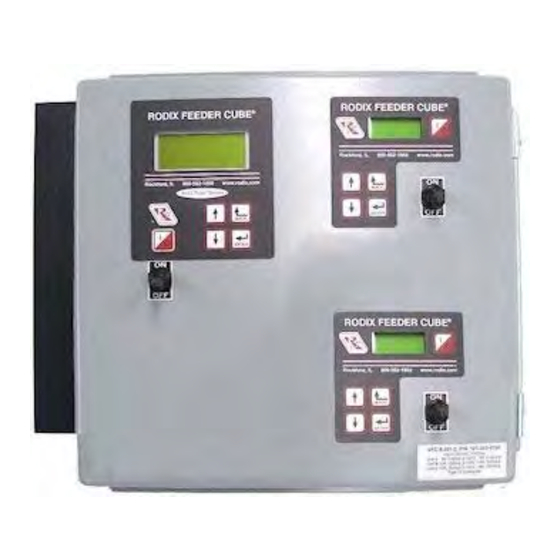
FEEDER CUBE ®
VFC-9-201-2, P/N 121-200-0785
OIL RESISTANT MODEL
IMPORTANT: APPLICATION NOTE
Input: 120 VAC, 50/60 HZ.
(Operating range 90-130 VAC)
Outputs: 0 - 120 VAC
Rated for IP54 environment
Unit A ratings
Input Fuse Size: 5 amps
Output Frequency: 5 - 300Hz
Rated Output Current: 9 Amps
Units B & C ratings
Input Fuse Size: 15 amps
Output Frequency: Same as Utility Frequency
Output Current: 100% Duty Cycle 0.6-12A per unit, 80% for 13-15A
Unit A Information: The Autotune Series of Variable Frequency Feeder Cubes® generates an output frequency for feeding
that is independent from the power line frequency. An optional vibration sensor, P/N 123-215, can be used to maintain the
vibratory feeder at a constant feed rate. The start/stop operation of the output can be controlled with an optional parts
sensor. For more information on this control, refer to the enclosed Adjustments and Set Up pages.
Units B & C Information: These units are based on the FC-200 Series Part Sensing Feeder Cube®. The start/stop operation
of the output can be controlled with an optional parts sensor. For more information on these units, refer to the enclosed
Adjustments and Set Up pages. Unit B is interlocked (subordinate) to the operation of Unit A so that Unit B operates only
when Unit A is feeding parts. The Unit C operation is independent of the other units. The interlocks can be reconfigured.
© 2005, 2017 RODIX
RODIX INCORPORATED
TOLL FREE (800) 562-1868, FAX (815) 316-4701
E-mail custserve@rodix.com
rodix.com
.
INC
5/9
/2017 Page 1
Advertisement
Table of Contents

Subscribe to Our Youtube Channel
Related Manuals for Rodix Auto Tune Series


Summary of Contents for Rodix Auto Tune Series
- Page 1 Adjustments and Set Up pages. Unit B is interlocked (subordinate) to the operation of Unit A so that Unit B operates only when Unit A is feeding parts. The Unit C operation is independent of the other units. The interlocks can be reconfigured. © 2005, 2017 RODIX /2017 Page 1...
- Page 2 FC-200 CONTROL FEEDER BOWL/HOPPER LOW VOLTAGE INPUT 1N4006 DIODE RODIX INC. INTERLOCK SWITCHING RUN JUMPER INPUT (Remove Run Jumper and FC-200/90 PLUS SERIES TB2, OUTPUT FEEDER CUBE AIR VALVE apply DC Voltage from PLC) 12VDC, <1 WATT VF Series...
-
Page 3: Adjustments & Set Up
Bowl/Hopper Interlock “+” and “sig” (see TB2 on the hoppers and linear inline feeders. The VF Series for proper cooling. wiring diagram) can be connected to a Rodix FC-40 output frequency can be adjusted to match the Plus All-Purpose Series control (TB2-11 & 12) when The VF-18 control and heat sink are cooled by a fan. -
Page 4: Software Adjustments
setting. For 208 and 240VAC applications, cut the plug off the tooling, reduces spring shock, and can D. The Arrow Up key allows the user to step up end(s) off and make proper plug-in connections for eliminate hammering when the control turns ON. The through the program menu or to increase a the factory’s power lines. - Page 5 bowl is much like finding a station on the AM radio band range larger before a reaction takes place. The Min Frequency adjustment specifies the band. Set the amplitude to about 30%. Then This setting normally doesn’t need to be changed. frequency used when the 0-10VDC input is at adjust the frequency across its range.
- Page 6 If an “Over A. The control comes with the security setting Feeder Cube® and Auto Tune® are registered TM of Rodix Inc. Current” occurs, press the “1/0” key to restart the “Unlocked” so the control can be set up. The Banner...
-
Page 7: Sensor Option
Steps to Interlock Two VF Series Controls together If a PLC is interfaced to both controls, optical isolation is necessary, see step 4 below. 1. Remove the run jumper from TB2 terminals 8 & 9 of the subordinate control. 2. Add a wire from terminal 3 of the master control to terminal 8 of the subordinate control. 3. -
Page 8: Normal Operation Display
Control Menu Layout for VF-3, VF-9 Normal Operation Display Press and hold ‘Enter’ key to enter the program menu or get to the security menu. Then use the “Enter” key to move right from Main Menu to Sub Menu to the Adjustable Setting. Use the “Back” key to move left. Main Menu Sub Menu Adjustable Setting... - Page 9 The cable should www.rodix.com is in the same direction as the vibration of the hang straight down from the sensor without touching feeder. The double-ended arrow in figure 1 shows © 2005 RODIX INC. VF-9 CFRsensor 171704.doc...
- Page 10 The Feeder Bowl/Hopper Interlock feature (TB2-1 & provide a standard North American receptacle input, soft start adjustment, minimum and maximum 2) can be connected to a Rodix FC-40, FC-90, FC- (NEMA 5-15R) for connection to the feeder. 240V output adjustments, full wave/half wave selection, 200 or VF Series control when control of a bulk models have a pigtail output cord.
- Page 11 SOFTWARE ADJUSTMENTS: unless the security feature lock has been selected. 13. SOFT-START Once the proper security code has been entered, the The start-up of the control’s output can be adjusted DISPLAY MESSAGES: The normal operating power may be adjusted under the “Power Settings” to ramp up to the desired output level instead of display shows the status of the control with regard to menu.
- Page 12 B. The “Constant On” feature can be used to keep shows certain software registers that may be Axis of the bowl running while the Aux output switches a helpful to Rodix staff while troubleshooting. Vibration device (air valve) to blow the unneeded parts back 1.375 into the bowl.
-
Page 13: Warranty
Connect the PLC to the 0-5VDC Analog input and the adhesive to fully cure at 70°F (21°C). If under warranty, Rodix will repair or replace your control verify the “Ext Sig” sub menu selection is set to CFR Alternatively, #8 or M4 screws can be used to mount at no charge;... - Page 14 FC-200 Series Menu Layout Press ‘Enter’ to enter program menu Normal Operation Display or get to the security menu. Press “Back” key to exit menu. Use the arrow UP and DOWN keys to adjust the security number. Press enter to test the security number. Sub Menu Control Setting Adjustments Power Settings...
- Page 15 Rodix controls have been designed with a AUX output. The shield “drain” wire high degree of immunity to electrical should be tied to the chassis in the Rodix RECTIFIER noise; however, depending on the control RELAY DIODE control. The drain wire should be kept...
Need help?
Do you have a question about the Auto Tune Series and is the answer not in the manual?
Questions and answers