Advertisement
Quick Links
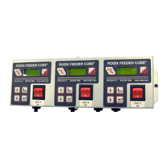
FEEDER CUBE ®
FC-200-3-240, P/N 121-000-2064
GENERAL PURPOSE MODEL
IMPORTANT: APPLICATION NOTE
Input: 240 VAC, 50/60 HZ.
(Operating range 180-250 VAC)
Triple Unit Fuse Sizes:
Unit A 5A, Unit B 8A, Unit C 2A
Output: 0-240 VAC
Unit A: 100% Duty Cycle 0.6-4A, 80% for 5A
Unit B: 100% Duty Cycle 0.6-6.4A, 80% for 7-8A
Unit C: 100% Duty Cycle 0.6-1.6A, 80% for 2A
Circuit Board P/N 24-201
Unit A Information: This unit is based on the FC-200 Series Part Sensing Feeder Cube®. The start/stop operation of the
output can be controlled with an optional parts sensor. For more information on this unit, refer to the enclosed Adjustments
and Set Up pages. Unit A is interlocked (subordinate) to the operation of Unit B so that Unit A operates only when Unit B is
feeding parts.
Unit B Information: This unit is based on the FC-200 Series Part Sensing Feeder Cube®. The start/stop operation of the
output can be controlled with an optional parts sensor. For more information on this unit, refer to the enclosed Adjustments
and Set Up pages.
Unit C Information: This unit is based on the FC-200 Series Part Sensing Feeder Cube®. The start/stop operation of the
output can be controlled with an optional parts sensor. For more information on this unit, refer to the enclosed Adjustments
and Set Up pages. The Unit C operation is independent of the other units.
© 2009, 2018 RODIX
RODIX INCORPORATED
TOLL FREE (800) 562-1868, FAX (815) 316-4701
E-mail custserve@rodix.com
rodix.com
.
INC
File No. E183233
FC-200-3-240 G.docx 5/7/2018 Page 1
Advertisement

Related Manuals for Rodix FEEDER CUBE FC-200 Series


Summary of Contents for Rodix FEEDER CUBE FC-200 Series
- Page 1 For more information on this unit, refer to the enclosed Adjustments and Set Up pages. The Unit C operation is independent of the other units. © 2009, 2018 RODIX FC-200-3-240 G.docx 5/7/2018 Page 1...
- Page 2 RUN JUMPER INPUT FEEDER BOWL/HOPPER LOW VOLTAGE INPUT RODIX INC. INTERLOCK SWITCHING P/N 24-200/24-201 FC-200/90 PLUS SERIES TB2, OUTPUT FEEDER CUBE (DC Voltage from PLC) LOW CURRENT SWITCH 5-30 VDC INPUT VOLTAGE FC-200 Series OFF/ON CONTROL WIRING DIAGRAM ...
-
Page 3: Adjustments & Set Up
The Feeder Bowl/Hopper Interlock feature (TB2-2 & input, soft start adjustment, minimum and maximum The 120VAC models in general purpose enclosures 3 ) can be connected to a Rodix FC-40, FC-90 or FC- output adjustments, full wave/half wave selection, provide a standard North American receptacle... - Page 4 SOFTWARE ADJUSTMENTS: unless the security feature lock has been selected. 13. SOFT-START Once the proper security code has been entered, the The start-up of the control’s output can be adjusted DISPLAY MESSAGES: The normal operating power may be adjusted under the “Power Settings” to ramp up to the desired output level instead of display shows the status of the control with regard to menu.
- Page 5 B. The “Constant On” feature can be used to keep shows certain software registers that may be Axis of the bowl running while the Aux output switches a helpful to Rodix staff while troubleshooting. Vibration device (air valve) to blow the unneeded parts back 1.375 into the bowl.
-
Page 6: Warranty
Connect the PLC to the 0-5VDC Analog input and the adhesive to fully cure at 70°F (21°C). If under warranty, Rodix will repair or replace your control verify the “Ext Sig” sub menu selection is set to CFR Alternatively, #8 or M4 screws can be used to mount at no charge;... - Page 7 FC-200 Series Menu Layout Normal Operation Display Press ‘Enter’ to enter program menu or get to the security menu. Press “Back” key to exit menu. Use the arrow UP and DOWN keys to adjust the security number. Press enter to test the security number. Sub Menu Control Setting Adjustments Power Settings...
-
Page 8: Rodix Solution
Rodix controls have been designed with a AUX output. The shield “drain” wire high degree of immunity to electrical RECTIFIER should be tied to the chassis in the Rodix noise; however, depending on the control RELAY DIODE control. The drain wire should be kept...
Need help?
Do you have a question about the FEEDER CUBE FC-200 Series and is the answer not in the manual?
Questions and answers