Advertisement
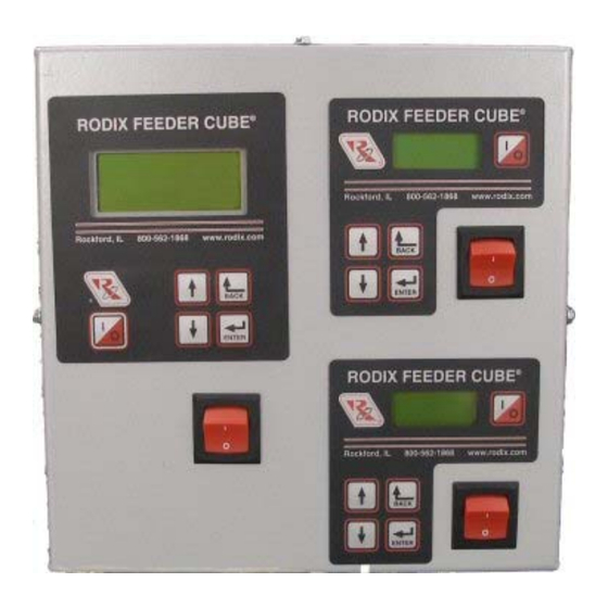
FEEDER CUBE ®
VFC-3-200-2, P/N 121-200-0782
GENERAL PURPOSE MODEL
IMPORTANT: APPLICATION NOTE
Input: 120 VAC, 50/60 HZ.
(Operating range 90-130 VAC)
Outputs: 0 - 120 VAC
Unit A ratings
Input Fuse Size: 5 amps
Output Frequency: 5 - 180Hz
Rated Output Current: 3 Amps
Unit B & C ratings
Input Fuse Size: 5 amps
Output Frequency: Same as Utility Frequency
Output Current: 100% Duty Cycle 0.6-3A
Unit A Information: The Autotune Series of Variable Frequency Feeder Cubes® generates an output frequency for feeding
that is independent from the power line frequency. An optional vibration sensor, P/N 123-215, can be used to maintain the
vibratory feeder at a constant feed rate. The start/stop operation of the output can be controlled with an optional parts
sensor. For more information on this control, refer to the enclosed Adjustments and Set Up pages.
Units B & C Information: Each unit is based on the FC-200 Series Part Sensing Feeder Cube®. The start/stop operation
of the output can be controlled with an optional parts sensor. For more information on each unit, refer to the enclosed
Adjustments and Set Up pages. Unit B is interlocked (subordinate) to the operation of Unit A so that Unit B operates only
when Unit A is feeding parts. The interlock can be reconfigured. The Unit C operation is independent of the other units.
© 2010, 2024 RODIX
INC
RODIX INCORPORATED
TOLL FREE (800) 562-1868, FAX (815) 316-4701
E-mail custserve@rodix.com
.
rodix.com
File No. E183233
4/17/24
Page 1
Advertisement
Table of Contents

Related Manuals for Rodix FEEDER CUBE VFC-3-200-2


Summary of Contents for Rodix FEEDER CUBE VFC-3-200-2
- Page 1 Adjustments and Set Up pages. Unit B is interlocked (subordinate) to the operation of Unit A so that Unit B operates only when Unit A is feeding parts. The interlock can be reconfigured. The Unit C operation is independent of the other units. © 2010, 2024 RODIX 4/17/24...
- Page 2 RODIX INC. FEEDER CUBE VF Series WIRING DIAGRAM VFC-3-200-2 H.docx Figure 1 11/20/20 Page 2...
- Page 3 Control Menu Layout for VF Series Normal Operation Display Press and hold ‘Enter’ key to enter the program menu or get to the security menu. Then use the “Enter” key to move right from Main Menu to Sub Menu to the Adjustable Setting.
-
Page 4: Adjustments & Set Up
Bowl/Hopper Interlock “sig” and “-“ (see TB2 on the hoppers and linear inline feeders. The VF Series for proper cooling. wiring diagram) can be connected to a Rodix FC-40 output frequency can be adjusted to match the Plus All-Purpose Series control (TB2-11(-) &... - Page 5 E. The “1/0” key allows the user to temporarily stop The variable frequency control is energy efficient menu. The soft start can be set from 0.0 to 10.0 or to start the control’s operation. When the LCD because it recaptures energy from the feeder electro- seconds.
- Page 6 14. Frequency Settings 15. Resonate Threshold Level The Min Frequency adjustment specifies the The “Frequency” menu contains the portion of the The “Resonate Threshold Level” setting sets the frequency used when the 0-10VDC input is at minimum level of vibration that the control considers menu that controls the frequency settings.
- Page 7 Feeder Cube® and Auto Tune® are registered TM of Rodix Inc. The CFR set point only appears on the display when When enabled, the security code is a number from Banner...
- Page 8 How to Interlock Two VF Series Controls together 4/8/20 Page 8 1. Remove the run jumper from TB2 terminals 8 & 9 of the subordinate control. 2. Add a wire from term. TB2-1 of the master control to terminal 7 of the subordinate control. 3.
- Page 9 The cable should is in the same direction as the vibration of the E-mail custserve@rodix.com, rodix.com hang straight down from the sensor without touching feeder. The double-ended arrow in figure 1 shows © 2005, 2020 RODIX INC. 123-215 VF-9 CFRsensor .doc...
- Page 10 The Feeder Bowl/Hopper Interlock feature (TB2-1 & provide a standard North American receptacle input, soft start adjustment, minimum and maximum 2) can be connected to a Rodix FC-40, FC-90, FC- (NEMA 5-15R) for connection to the feeder. 240V output adjustments, full wave/half wave selection, 200 or VF Series control when control of a bulk models have a pigtail output cord.
-
Page 11: Software Adjustments
SOFTWARE ADJUSTMENTS: unless the security feature lock has been selected. 13. SOFT-START Once the proper security code has been entered, the The start-up of the control’s output can be adjusted DISPLAY MESSAGES: The normal operating power may be adjusted under the “Power Settings” to ramp up to the desired output level instead of display shows the status of the control with regard to menu. -
Page 12: Default Memory
B. The “Constant On” feature can be used to keep shows certain software registers that may be Axis of the bowl running while the Aux output switches a helpful to Rodix staff while troubleshooting. Vibration device (air valve) to blow the unneeded parts back 1.375 into the bowl. -
Page 13: Troubleshooting
Connect the PLC to the 0-5VDC Analog input and the adhesive to fully cure at 70°F (21°C). If under warranty, Rodix will repair or replace your control verify the “Ext Sig” sub menu selection is set to CFR Alternatively, #8 or M4 screws can be used to mount at no charge;... - Page 14 FC-200 Series Menu Layout Normal Operation Display Press ‘Enter’ to enter program menu or get to the security menu. Press “Back” key to exit menu. Use the arrow UP and DOWN keys to adjust the security number. Press enter to test the security number. Sub Menu Control Setting Adjustments Power Settings...
-
Page 15: Rodix Solution
Rodix controls have been designed with a AUX output. The shield “drain” wire high degree of immunity to electrical should be tied to the chassis in the Rodix RECTIFIER noise; however, depending on the control RELAY DIODE control. The drain wire should be kept...
Need help?
Do you have a question about the FEEDER CUBE VFC-3-200-2 and is the answer not in the manual?
Questions and answers