Table of Contents
Advertisement
Quick Links
Owners Manual
NetDirector
16-Port Console Cat5
®
KVM over IP Switch
Este manual está disponible en español en la página de Eaton:
Tripplite.Eaton.com/support
Ce manuel est disponible en français sur le site Web de Eaton :
Tripplite.Eaton.com/support
Dieses Handbuch ist in deutscher Sprache auf der Eaton-Website verfügbar:
Tripplite.Eaton.com/support
Questo manuale è disponibile in italiano sul sito web di Eaton:
Tripplite.Eaton.com/support
Purchased product
may differ from image.
PRODUCT REGISTRATION
Register your product today for a
chance to win an ISOBAR
®
protector in our monthly drawing!
Tripplite.Eaton.com/warranty
Model:
B064C-16-1X1-IP
surge
1
Advertisement
Table of Contents

Related Manuals for Eaton TRIPP LITE NetDirector B064C-16-1X1-IP


Summary of Contents for Eaton TRIPP LITE NetDirector B064C-16-1X1-IP
- Page 1 Este manual está disponible en español en la página de Eaton: Tripplite.Eaton.com/support Ce manuel est disponible en français sur le site Web de Eaton : Tripplite.Eaton.com/support Dieses Handbuch ist in deutscher Sprache auf der Eaton-Website verfügbar: Tripplite.Eaton.com/support...
-
Page 2: Table Of Contents
Table of Contents 1. FCC Information 7. Administration 2. User Notice 7.1 IP Address Determination 3. Package Contents 7.1.1 IPv6 4. Introduction 7.1.2 Trusted Certificates 4.1 Overview 7.1.3 Self-Signed Private Certificates 4.2 Features 7.2 Super Administrator Setup 4.3 Requirements 7.2.1 First-Time Setup 4.3.1 General 7.2.2 Moving On 4.3.2 External Console... - Page 3 Table of Contents 7.9 Maintenance 8.5 Keyboard Emulation 7.9.1 Main Firmware Upgrade 8.5.1 Mac Keyboard 7.9.2 Recovering from Failed 8.5.2 Sun Keyboard Firmware Upgrade 8.6 Additional Video Resolution Procedures 7.9.3 Upgrade Adapters 8.6.1 Additional Mouse Synchronization 7.9.4 Adapter Firmware Upgrade Procedures (Windows, Sun, Linux) Recovery 8.7 PPP Modem Operation...
-
Page 4: Fcc Information
The user must use shielded cables and connectors with this equipment. Any changes or modifications to this equipment not expressly approved by Eaton could void the user’s authority to operate this equipment. 2. User Notice All information, documentation, and specifications contained in this manual are subject to change without prior notification by the manufacturer. -
Page 5: Introduction
4. Introduction 4.1 Overview The NetDirector Console KVM Switch IP-based KVM control units allow both a local and remote operator to monitor and access multiple servers from a single KVM (keyboard, video, mouse) console. The B064C-16-1X1-IP can control up to 16 servers in a single-stage setup. The B064C-16-1X1-IP features IP-based connectivity that allows one local and one remote operator to concurrently monitor and access the computers on your installation. - Page 6 4. Introduction • Multiplatform support: PC, Mac, Sun and serial. • Supports an external USB mouse. • Dual-rail housing is slightly less than 1U with top and bottom clearance for smooth operation in a 1U rack space. • Dual rail — LCD monitor slides independent of the keyboard / touchpad. Management •...
- Page 7 4. Introduction Advanced Security • Remote authentication support: RADIUS, LDAP, LDAPS and MS Active Directory. • Supports TLS 1.2 encryption and RSA 2048-bit certificates to secure user logins from browsers. • Flexible encryption design allows users to choose any combination of 56-bit DES, 168-bit 3DES, 256-bit AES, 128-bit RC4 or Random for independent KB/Mouse, video and virtual media data encryption.
-
Page 8: Requirements
4. Introduction 4.3 Requirements 4.3.1 General • Computers with at least a Pentium 4 2+ GHz processor and 1 GB RAM. • Browsers must support TLS 1.2 encryption. • Network transfer speed of at least 512 kbps is recommended. • For the Log Server, Microsoft Jet OLEDB 4.0 or higher driver installed. 4.3.2 External Console •... -
Page 9: Kvm Adapter Cables
4. Introduction 4.3.4 KVM Adapter Cables • Cat 5e/6 cable is required to connect the B064C-16-1X1-IP to one of the KVM adapters. • The following KVM adapters are required for use with the B064C-16-1X1-IP: Function Model Connect to devices with PS/2 ports B055-001-PS2 Connect to devices with USB ports (All platforms –... -
Page 10: Components
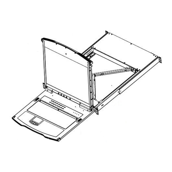
4. Introduction 4.4 Components 4.4.1 Front View Pull to slide the LCD module out; push to slide the module in. See 6.1.1 Upper Handle Opening the Console for more information. LCD Module Refer to 4.4.3 LCD Module, for a detailed description. Keyboard Module Refer to 4.4.2 Keyboard Module, for a detailed description. -
Page 11: Keyboard Module
4. Introduction 4.4.2 Keyboard Module Keyboard Standard 105-key QWERTY keyboard. Touchpad Standard mouse touchpad. A USB Type-A mouse port is provided for users who prefer to use an external External Mouse Port mouse. The Num Lock, Caps Lock, Scroll Lock LEDs are located here. Lock LEDs and Reset Button A reset button is located just to the right of the Lock LEDs. -
Page 12: Lcd Module
4. Introduction 4.4.3 LCD Module To access the LCD monitor, slide the LCD module out and flip up the cover. See LCD Display 6.1.1 Opening the Console for more information. These buttons control the position and picture settings of the LCD display. See LCD Controls 6.2 LCD OSD Configuration for more information. -
Page 13: Rear View
4. Introduction 4.4.4 Rear View 1 1 2 2 3 3 Grounding Terminal The grounding wire used to ground the switch attaches here. This is a standard C14 AC power socket. The power cord from an AC source Power Socket plugs in here. -
Page 14: Installation
5. Installation 5.1 General Safety Instructions • Read all of these instructions. Save them for future reference. • Follow all warnings and instructions marked on the device. • This product is for indoor use only. • Do not place the device on any unstable surface (cart, stand, table, etc.). If the device falls, serious damage will result. •... - Page 15 5. Installation Rack Mounting Safety Instructions • Prior to installation, ensure KVM is powered OFF and de-energized. • Before working on the rack, make sure the stabilizers are secured to the rack, extended to the floor and that the full weight of the rack rests on the floor.
-
Page 16: Standard Rack Mounting
5. Installation 5.2 Standard Rack Mounting A standard rack mount kit is provided with your B064C-16-1X1-IP. The kit enables the switch to be mounted in a rack with a depth of 15.5-30 in. (40-77 cm). Left and Right L-Brackets Side Mount Bracket Notes: •... - Page 17 5. Installation To rack mount the switch: 1. Have one person position the unit in the rack and hold it steady, then the second person attaches the front brackets to the rack. 2. While the first person continues to hold the unit in place, the second person slides the left and right L-brackets into the unit’s side mount brackets from the rear.
-
Page 18: Front-L Brackets Mounting
5. Installation 5.3 Front-L Brackets Mounting To better enable the tilt function of the LCD screen, install the front L-brackets at the front of the rack. 1. To attach the left and right front L-brackets to the front of the rack, first place screws in the tabs to secure them in place. - Page 19 5. Installation 3. While the first person continues to hold the unit in place, the second person slides the left and right L-Brackets into the unit’s side mount brackets from the rear. Secure the bracket using four screws. 4. Once the L-brackets are secured, tighten all screws. Allow at least 2 in.
-
Page 20: Single-Stage Installation
5. Installation 5.4 Single-Stage Installation In a single-stage installation, there are no additional switches daisy-chained down from the first unit. To set up your console KVM switch, refer to the following steps and installation diagram. Modem... - Page 21 5. Installation Ground the unit by connecting one end of a grounding wire to the grounding terminal and the other end of the wire to a suitable grounded object. Note: Do not omit this step. Proper grounding helps to prevent damage to the unit from power surges or static electricity. (Optional) If you choose to install an external console, plug your keyboard, monitor and mouse into the console ports located on the switch’s rear panel.
-
Page 22: Kvm Adapter Cable Installation
5. Installation 5.5 KVM Adapter Cable Installation B055-001-PS2 B055-001-SER B055-001-UDV B055-001-UDP B055-001-UHD B055-001-USB B055-001-USB-V2 B055-001-USB-VA B055-001-UV2CAC... -
Page 23: Hot Plugging
5. Installation 5.6 Hot Plugging Dual-Rail LCD Over-IP KVM Switches support hot plugging in which components can be removed and added back into the installation by unplugging and replugging cables from the ports without needing to shut the unit down. Note: If the server’s operating system does not support hot plugging, this function may not work properly. -
Page 24: Kvm Operation
6. KVM Operation 6.1 Basic Operation 6.1.1 Opening the Console The B064C-16-1X1-IP consists of two modules: an LCD display module located under the top cover and a keyboard / touchpad module below the LCD module. The modules can slide together or independently. This allows you to have the LCD display available for viewing while the keyboard / touchpad module is conveniently out of the way when not in use. - Page 25 6. KVM Operation 2. Pull out the top panel completely until it clicks into place. 3. Rotate the top panel backward to expose the LCD screen.
- Page 26 6. KVM Operation 4. Reach underneath and pull out the keyboard module completely until it clicks into place. Opening Together Refer to the diagrams in the Opening Separately section as you do the following: 1. While holding the release catch, pull the top and bottom panels out until the keyboard module clicks into place. Note: Once the console has been released, release the release catch.
-
Page 27: Closing The Console
6. KVM Operation Operating Precautions The maximum load bearing capacity of the keyboard module is 44 lb. (20 kg). Failure to heed the following information may result in damage to the keyboard module: Correct Rest your hands and arms lightly on the keyboard module as you work. Incorrect •... - Page 28 6. KVM Operation 2. Release the release catches. Using the front handle, push in the keyboard module completely. 3. Rotate the LCD module completely, then pull the rear release catches to release the LCD module.
-
Page 29: Lcd Osd Configuration
6. KVM Operation 4. Using the front handle, push in the module completely. 6.2 LCD OSD Configuration 6.2.1 LCD Buttons The LCD OSD allows you to set up and configure the LCD display. Four buttons are used to perform the configuration, as described in the table below: Button Function... -
Page 30: Adjustment Settings
6. KVM Operation 6.2.2 Adjustment Settings An explanation of the LCD OSD adjustment settings is provided in the table below: Setting Explanation Auto Adjust Auto adjust screen image and resolution Adjust OSD Positions and OSD Display Time Luminance Adjusts brightness and contrast level of the screen image. Language Selects the language that the OSD displays its menus in. -
Page 31: Administration
For client computers running Windows, an IP address can be assigned with the IP lnstaller utility. The IP Installer utility can be obtained from Eaton’s technical support or website. Look under DriverISW, and the model of your switch. After downloading the utility to your client computer, do the following: 1. -
Page 32: Ipv6
7. Administration Browser 1. Set your client computer’s IP address to 192.168.0.XXX Where XXX represents any number or numbers except 60 (192.168.0.60 is the default address of the B064C-16-1X1- IP). 2. Specify the switch’s default IP address (192.168.0.60) in your browser to connect. 3. -
Page 33: Trusted Certificates
7. Administration 7.1.2 Trusted Certificates When you try to log in to the B064C-16-1X1-IP from your Web browser, a Security Alert message will appear to inform you the device’s certificate is not trusted and ask if you want to proceed. The certificate can be trusted, but the alert is triggered because the certificate’s name is not found on Microsoft’s list of Trusted Authorities. - Page 34 7. Administration Installing the Certificate To install the certificate: 1. Go to Browser’s security setting and look for HTTPS/SSL certificate section. Start the Certificate Import Wizard. 2. Follow the steps and import the trusted certificate into the Trusted Root Certification Authorities Section, then click Finish.
-
Page 35: Self-Signed Private Certificates
• The command should be entered all on one line ( do not press [Enter] until all parameters have been keyed in). • If there are spaces in the input, surround the entry in quotes (e.g., “Eaton Corporation”). To avoid inputting information during key generation. the following additional parameters can be used: /C /ST /L /O / OU /CN /emailAddress. -
Page 36: Super Administrator Setup
7. Administration 7.2 Super Administrator Setup 7.2.1 First-Time Setup Once the KVM over IP switch has been connected, the Super Administrator will need to set up the unit for user operation. This involves setting the network parameters and changing the default Super Administrator login. The most convenient way to do this for the first time is from the local console. - Page 37 7. Administration Network Setup To set up the network, do the following: 1. Click the Device Management tab. 2. Select the Network tab. 3. Fill in the fields according to the information provided under XX Network. Changing the Super Administrator Login 1.
-
Page 38: Moving On
7. Administration 2. Click Administrator in the left panel. Select administrator in the central panel, then click Modify at the bottom of the page. The User Information page will appear: 3. Change the Username and Password to something unique. 4. Enter the password again in the Confirm Password field to confirm it is correct. 5. -
Page 39: Logging In
7. Administration 7.3 Logging In KVM over IP switches can be accessed from a local console, an Internet browser, a Windows application (AP) program and a Java application (AP) program. No matter which access method you choose, the KVM over IP switch’s authentication procedure requires you to submit a valid username and password. -
Page 40: Browser Login
7. Administration 7.3.2 Browser Login KVM over IP switches can be accessed via an Internet browser running on any platform. To access the switch: 1. Open the browser and specify the IP address of the switch you want to access in the browser’s location bar. Note: For security purposes, a login string may have been set by the administrator. - Page 41 7. Administration To connect to the B064C-16-1X1-IP, click the WinClient.exe program icon (on your desktop) to access the Windows Client Connection screen: Windows Client AP Connection Screen Item Description Menu Bar The Menu Bar contains two items: File and Help. •...
- Page 42 7. Administration Connecting - Windows Client AP 1. From the Server List box, double-click the device that you wish to connect to. - Or - Specify its IP address and port number in the Server IP and Port input boxes. 2.
-
Page 43: Java Client Ap Login
7. Administration 7.3.4 Java Client AP Login In those cases in which the Administrator does not want the KVM over IP switch to be available via browser access, but the local client users aren’t running Windows, the Java AP Client provides direct remote access to non-Windows systems users (although you initially download the Java AP Client program from the browser page, see 7.10 Download). -
Page 44: User Interface
7. Administration Connecting - Java Client AP To connect to a KVM switch, do the following: 1. From the Server List box, double-click the device that you wish to connect to. - Or - Specify its IP address and port number in the Server IP and Port input boxes. 2. -
Page 45: Web Browser Main Page
There is a Filter button at the bottom of the Sidebar that lets you expand or narrow the scope of the ports that appear in the tree. Eaton Logo Eaton Logo directs user to the official Eaton website https://tripplite.eaton.com/. Click this button for user information, configure user preferences settings, change User Settings password, logout and online help. - Page 46 Logout Log out and end the session. Access Online Help Click to visit the Eaton Website. User Preferences The User Preferences page allows users to set up their own individual working environments. The switch stores a separate configuration record for each user profile and sets up the working configuration according to the Username...
- Page 47 7. Administration Setting Function Language Selects the language the interface displays in. OSD Hotkey Selects which Hotkey controls the GUI function: [Scroll Lock]. [Scroll Lock] is the default. To select a different combination, click the arrow at the right of the box to drop down the list of choices.
- Page 48 7. Administration Tab Bar The number and type of icons that appear on the Tab Bar at the top of the page are determined by the user’s type (Super Administrator, Administrator, User) and the permissions assigned when the user’s account was created. The functions associated with each of the icons are explained in the table below: Icon Function...
-
Page 49: Ap Gui Main Page
7. Administration 7.4.2 AP GUI Main Page With WinClient AP and Java Client AP access, once users log in (see 7.3 Logging ln), the GUI Main Page will open: The GUI Main Page is similar to the Web Browser. The differences between them are as follows: 1. -
Page 50: Local Console Gui Main Page
7. Administration 7.4.3 Local Console GUI Main Page The Local Console GUI Main Page is similar to the Java and Windows AP GUI Main Page: The major difference is that the Local Console Main Page does not have a tab for Download. Mounting Virtual Media Locally Local console supports virtual media mounting. -
Page 51: Control Panel
7. Administration 3. On the Virtual Media Settings dialog box that appears, click Add to select your virtual media. Note: The mounting virtual media settings are similar to those of via Windows / Java Client Viewer. 7.4.4 Control Panel WinClient Control Panel Since the WinClient Control Panel contains the most complete functionality, this section describes the WinClient Control Panel. - Page 52 7. Administration • Right-clicking in the text row area opens a menu-style version of the toolbar. In addition, it allows you to select options for the Screen Mode, Zoom, Mouse Pointer type and Mouse Pointer. • To move the Control Panel to a different location on the screen, place the mouse pointer over the text row area, then click and drag.
- Page 53 7. Administration Icon Function Under an accessed port, click to begin Auto Scan Mode. The KVM over IP switch automatically switches among the ports that were selected for Auto Scanning with the Filter function. This allows you to monitor their activity without having to switch among them manually.
- Page 54 7. Administration Hotkeys Various actions related to manipulating the remote server can be accomplished with hotkeys. The Hotkey Setup utility (accessed by clicking the icon) lets you configure which hotkeys perform the actions. The hotkeys that invoke an action are shown to the right of its name. Use the checkbox to the left of an action’s name to enable or disable its hotkey.
- Page 55 7. Administration Action Explanation Substitute Ctrl key If your local client computer captures Ctrl key combinations and prevents them from being sent to the remote server, you can implement their effects on the remote server by specifying a function key to substitute for the Ctrl key. If you substitute the F11 key, for example, pressing [F11 + 5] would appear to the remote server as [Ctrl + 5].
- Page 56 7. Administration 3. Click Record. The dialog box disappears and a small panel appears at the top left of the screen: 4. Press the keys for the macro. • To pause macro recording, click Pause. To resume, click Pause again. •...
- Page 57 7. Administration 6. If you want to change any of the keystrokes, select the macro and click Edit. This will open a dialog box similar to the one for Show. You can change the content of your keystrokes, change their order, etc. 7.
- Page 58 7. Administration Search Located at the bottom of the dialog box, the Search button lets you filter the list of macros that appear in the large upper panel for you to play or edit. Click a radio button to choose whether you want to search by name or by key, key in a string for the search, then click Search.
- Page 59 7. Administration 4. Press the keys for the macro. • To pause macro recording, click Pause. To resume, click Pause again. • Clicking Show opens a dialog box that lists each keystroke that you make, together with the amount of time each one takes.
- Page 60 7. Administration Video Settings Clicking the Video Settings icon on the Control Panel opens the Basic Video Settings dialog box with basic settings. The options in the basic dialog box allow you to adjust the Screen Position, set Auto-Sync and slide the Performance bar setting.
- Page 61 7. Administration The meanings of the video adjustment options are provided in the table below: Options Description Preset / Custom Using the Preset and Custom buttons allow you to set and save custom video settings and revert to default video settings. Performance Use the slide bar to select the type of Internet connection the local client computer uses.
- Page 62 7. Administration The Message Board The B064C-16-1X1-IP supports multiple user logins, which may cause access conflicts. To alleviate the problem, a message board is provided to allow users to communicate with one other: Button Bar The buttons on the Button Bar are toggles. Button Action Enable/Disable Chat: When disabled, messages posted to the board are not...
- Page 63 7. Administration User List Panel The names of all the logged in users are listed in this panel. • Your name appears in blue and other users’ names appear in black. • By default, messages are posted to all users. To post a message to an individual user, select the user’s name before sending your message.
- Page 64 7. Administration Mounting Virtual Media 1. Click the Virtual Media icon to open the Virtual Media dialog box. Note: The T button at the top right opens a slider to adjust the transparency of the dialog box. After making your adjustment, click anywhere in the dialog box to dismiss the slider.
- Page 65 7. Administration 5. Read refers to the redirected device being able to send data to the remote server and Write refers to the redirected device being able to have data from the remote server written to it. For the redirected device to be writable as well as readable, click to put a check in the Enable Write checkbox: Note: If a redirected device cannot be written to, it will appear in gray.
- Page 66 7. Administration Zoom The Zoom icon controls the zoom factor for the remote view window. Settings are as follows: Setting Description 100% Sizes and displays the remote view window at 100%. Sizes and displays the remote view window at 75%. Sizes and displays the remote view window at 50% Sizes and displays the remote view window at 25% Sizes and displays the remote view window at 100%.
- Page 67 7. Administration Resizing the Keyboard 1. Click the down arrow next to the currently selected keyboard size, to drop down the sizing list. Selecting Platforms The on-screen keyboard supports the Sun and PC platforms. To select the platform: 1. Click the down arrow next to the currently selected platform for drop-down of the platform list to appear. 2.
- Page 68 7. Administration Mouse Pointer Type KVM over IP switches offer several mouse pointer options when working in the remote display. Click this icon to select from the available choices: Notes: • Before accessing a port it is important to know the Single option is not available. Once the port is accessed, all four pointers are available.
- Page 69 7. Administration Mac and Linux Considerations • For Mac OS versions 10.4.11 or later, there is a second DynaSync setting to choose from: if the default Mouse DynaSync result is not satisfactory, try the Mac 2 setting. To select Mac 2, right-click in the text area of the Control Panel and select Mouse Sync Mode ...
- Page 70 7. Administration Control Panel Configuration Clicking the Control Panel icon opens a dialog box that allows you to configure the items that appear on the Control Panel as well as its graphical settings: The organization of the dialog box is described in the table below: Item Description •...
- Page 71 7. Administration Item Description These settings allow the user to configure B064C-16-1X1-IP’s screen-capture parameters: • Path lets you select a directory that the captured screens automatically get saved to. Click Browse and navigate to the directory of your choice, then click OK. If you do not specify a directory here, the snapshot is saved to your desktop.
- Page 72 7. Administration Icon Function Under an accessed port, click to begin Auto Scan Mode. The KVM over IP switch automatically switches among the ports that were selected for Auto Scanning with the Filter function. This allows you to monitor their activity without having to switch among them manually.
- Page 73 7. Administration WebClient Control Panel The WebClient Viewer is similar to the one used by the WinClient but with fewer functions. The Control Panel functions are described in the table below: Icon Function This is a toggle. Click to make the Control Panel persistent (e.g., it always displays on top of other screen elements).
-
Page 74: Port Access
7. Administration The major differences between the WinClient and WebClient are: • The Recall is not available. • The Zoom is not available. • The Auto Scan Mode is not available. • The Dot mouse pointer type is not available. •... -
Page 75: Sidebar
7. Administration AP GUI The Connections page is organized into several main areas. All devices and ports that a user are permitted to access are listed in the Sidebar at the left of the page. After selecting a device or port in the Sidebar, clicking entries on the menu bar (Browser GUI) or tab bar (AP GUI) opens information and configuration pages related to the item selected in the Sidebar. - Page 76 7. Administration Sidebar Tree Structure • Users are only allowed to see the devices and ports they have access permission for. • Ports and chained station devices can be nested under their first station devices. Click the + in front of a device to expand the tree and see the ports nested underneath it. Click the - to collapse the tree and hide the nested ports.
- Page 77 7. Administration Choices Explanation If you key in a search string and click Search, only port names that match the search string display in the tree. Wildcards (? for single characters; * for multiple characters) and the keyword “or” are supported, so that more than one port can show up in the list.
- Page 78 7. Administration Port/Outlet Naming For convenience – especially in large installations with many devices, ports – administrators and users with port configuration permission can give each port or outlet a name. To assign, modify or delete a name, do the following: 1.
-
Page 79: Kvm Devices And Ports - Connections Page
7. Administration 7.5.2 KVM Devices and Ports – Connections Page The Connections page displays port status information at the device level, and port connection configuration options at the port level. Device Level When a B064C-16-1X1-IP is selected in the Sidebar, the Connections page displays a list of ports for the device that the user is authorized to access or view. - Page 80 7. Administration Port Level When a port is selected in the Sidebar, the Connections page displays port connection configuration properties: Status The Status Panel displays the port’s current status information, including whether the port is online or offline and if the port is mountable.
-
Page 81: Blade Servers - Connections Page
7. Administration 7.5.3 Blade Servers – Connections Page Blade Servers connected to the switches display below the KVM switches in the Sidebar. By associating a blade server or blade with a port, the servers and blades are integrated into the Sidebar tree view and appear as devices connected to the port. - Page 82 7. Administration Associating Ports Main Panel Device View Port association begins by clicking the Blade Configuration menu item at the far right of the menu bar. The page appears in Device View, listing all the KVM switch’s ports and blade servers (IBM and Dell servers) or individual blades (HP servers) associated with them.
- Page 83 7. Administration Main Panel Blade View At the bottom of the Device View main panel is a button labeled Blade View. This is a button that toggles the main panel between the two views. Click it to open the main panel in Blade View: Blade View lists all the blade servers (IBM and Dell servers) and individual blades (HP servers) that are installed on the system, as well as the ports (if any) they are associated with.
-
Page 84: History
7. Administration Unassociating Ports To break the association between a port and a blade server or individual blade, select the association in the main panel, then click Unassociate. 7.5.4 History The History page provides a record of each time that a port was accessed and quick access to the most recently used ports. - Page 85 7. Administration 2. This will be a container to hold your port entries. Click inside the text entry box to erase Untitled Favorite and key in an appropriate name, then click on any empty space in the main panel. 3. To add a port: Drag it from the Sidebar and drop it onto the container.
-
Page 86: Sessions
7. Administration 7.5.6 Sessions The Session page lets the administrator and users with User Management permissions see at a glance which users are currently logged into the KVM over IP switch and provides information about each of their sessions. Notes: •... -
Page 87: Access
7. Administration 7.5.7 Access Administrators use the Access page to set user and group access and configuration rights for switches and ports. Note: The Access page only appears for those users with User Management permissions. It is not available for other users. Device Level Browser GUI If a switch is chosen in the Sidebar, the Main panel looks similar to the one shown below:... - Page 88 7. Administration The main panel consists of two columns: Name, and Config: • Name lists all the users and groups that have been created. • Config indicates the users who have Configuration privileges. A check mark (√) indicates the user has permission to make changes to the switch configuration settings (see 7.7 Device Management) and an X indicates the user is denied permission to make configuration changes.
- Page 89 7. Administration The port access settings are explained in the following table: Name Each port accessible to the user is listed under the Names column. The Access column is where device access rights are set. To cycle through the choices, click the icon in the row that corresponds to the user you want to configure.
- Page 90 7. Administration The page is essentially the same as the one for the Browser GUI, with the exception that there are filters at the top of the columns. The filters allow you to expand or limit the scope of the users and groups that are displayed, as described in the following table: Filter Description...
-
Page 91: Port Configuration
7. Administration The page is essentially the same as the one for the Browser GUI, with the exception that there are filters at the top of the columns. The filters allow you to expand or limit the scope of the users and groups that are displayed, as described in the following table: Filter Description... - Page 92 7. Administration The Occupy Timeout field sets a time threshold for users on ports whose Access Mode has been set to Occupy. If there is no activity from the user occupying the port for the time duration set here, the user is timed out and the port is released.
- Page 93 7. Administration • The Status panel provides information as to whether the port is online or offline, the adapter cable used to connect the server (or other device) to the port and the adapter’s firmware level. • The Properties panel allows you to make configuration settings for the selected port. •...
-
Page 94: User Management
7. Administration Associated Links The Associated Links page provides a method of associating other ports on the same switch to the selected port. This function is primarily intended to be used when connecting both KVM and serial ports (KA7140) from a single server to the switch. - Page 95 7. Administration AP GUI The page is organized into two main areas: the Sidebar at the left, and the large main panel at the right. • Users and groups appear in the panel at the left of the page. The large panel at the right provides more detailed information for each.
-
Page 96: Users
7. Administration 7.6.1 Users The B064C-16-1X1-IP supports three types of user accounts: User Type Role Access and manage ports and devices. Manage Users. Configure the overall Super Administrator installation. Configure personal working environment. Access and manage authorized ports and devices. Manage Users. Configure personal Administrator working environment. - Page 97 7. Administration Field Description There are three categories: Super Administrator, Administrator and User. There is no limitation on the number of accounts that can be created in each category. • The Super Administrator is responsible for the overall installation configuration and maintenance, user management and device and port assignments.
-
Page 98: Groups
7. Administration 4. At this point you can assign the new user to a group by selecting the Groups tab. You can also assign the user’s port access rights by selecting the Devices tab. Note: Optionally, you can skip this step now and return to it later. 5. - Page 99 7. Administration 2. Click Add at the bottom of the main panel. The Group notebook opens, with the Group tab selected: 3. Enter the required information in the appropriate fields. A description of each of the fields is provided in the table below: Field Description...
-
Page 100: Users And Groups
7. Administration Deleting Groups To delete a group: 1. In the Sidebar, click the Groups icon. 2. In the main panel, select the group’s name. 3. Click Delete. 4. Click OK. 7.6.3 Users and Groups There are two ways to manage users and groups: from the Users notebook and from the Group notebook. Note: Before you can assign users to groups, you must first create them. - Page 101 7. Administration Removing Users from a Group from the User’s Notebook To remove a user from a group from the User’s notebook: 1. In the Sidebar User list, click the user’s name – or – In the main panel, select the user’s name. 2.
- Page 102 7. Administration Assigning Users to a Group from the Group’s Notebook 1. In the Sidebar Group list, click the group’s name – or – In the main panel, select the group’s name. 2. Click Modify. 3. In the Group notebook that appears, select the Members tab. 4.
- Page 103 7. Administration Removing Users from a Group from the Group’s Notebook 1. In the Sidebar Group list, click the group’s name – or – In the main panel, select the group’s name. 2. Click Modify. 3. In the Group notebook that comes up, select the Members tab. 4.
-
Page 104: Device Assignment
7. Administration 7.6.4 Device Assignment When a user logs in to the KVM over IP switch, the interface will appear with the Port Access page displayed. All ports that the user are permitted to access are listed in the Sidebar at the left of the page. Access permissions for those ports and the devices connected to them are assigned on a port-by-port basis from the User or Group list on the Sidebar of the User Management page. - Page 105 7. Administration USB: The USB column is where USB Virtual Media device access rights are listed. This entry does not appear for switches that do not support the USB Virtual Media function. Click the icon in the row that corresponds to the port you want to configure to cycle through the choices.
-
Page 106: Device Management
7. Administration Assigning Device Permissions from the Groups’ Notebook To assign device permissions to a Group of users, do the following: 1. In the Sidebar Groups list, click the group’s name. – or – In the main panel, select the group’s name. 2. - Page 107 7. Administration AP GUI General The General section of the Device Information page displays the name of the selected device, its firmware version, the FPGA (Field-Programmable-Gate-Array) and information about its network configuration. Note: The AP GUI version presents the same information as the Browser version. Scroll through the list to see the additional entries. Operating Mode...
- Page 108 7. Administration The Operating Mode page is used to set working parameters: • If Force all to grayscale is enabled, the remote displays of all devices connected to the KVM over IP switch are changed to grayscale. This can speed up I/O transfer in low bandwidth situations. •...
- Page 109 7. Administration IP Installer The IP Installer is an external Windows-based utility for assigning IP addresses to the KVM over IP switch. Click one of the radio buttons to select Enable, View Only or Disable for the IP Installer utility. Notes: •...
- Page 110 7. Administration • IPv4 Settings • IP Address IPv4 is the traditional method of specifying IP addresses. The KVM over IP switch can either have its IP address assigned dynamically (DHCP) or it can be given a fixed IP address. o For dynamic IP address assignment, select the Obtain IP address automatically radio button (this is the default setting).
- Page 111 7. Administration Event Destination • SMTP Settings To have the KVM over IP switch email reports from the SMTP server to you, do the following: 1. Enable the Enable report from the following SMTP server and key in either the IPv4 address, IPv6 address or domain name of the SMTP server.
- Page 112 7. Administration • SNMP Trap To be notified of SNMP trap events: 1. Check Enable SNMP Agent. 2. Key in either the IPv4 address, IPv6 address, or domain name of the computer to be notified of SNMP trap events. 3. Key in the port number. The valid port range is 1–65535. Note: The logs that are notified of SNMP trap events are configured on the Notification Settings page under the Log tab (see 7.8 Log Notification Settings for details).
- Page 113 636. Consult the LDAP / LDAPS administrator to ascertain the appropriate entry for this field. For example, the entry might look like this: Admin DN ou=B064C161X1IP,dc=eaton,dc=com Admin Name Key in the LDAP administrator’s username. Password Key in the LDAP administrator’s password.
- Page 114 7. Administration On the LDAP / LDAPS server, Users can be authenticated with any of the following methods: • With MS Active Directory schema. • Without schema – Only the Usernames used on the KVM over IP switch are matched to the names on the LDAP / LDAPS server.
- Page 115 6. Select the Access Type and click Save. 7. From a MIB browser, import the MIB file and enter the IP address of the switch. Note: Download the Eaton B064C MIB file on Eaton’s website from the B064C-16-1X1-IP product page. OOBC In case the KVM over IP switch cannot be accessed with the usual LAN-based methods, it can be accessed from the switch’s modem port.
- Page 116 7. Administration Enable Dial Back As an added security feature, if this function is enabled the switch disconnects the calls that dial in to it and dials back to one of the entries as specified in the table below: Item Action If Fixed Number Dial Back is enabled, when there is an incoming call, the KVM over IP switch hangs up the modem and dials back to the modem whose phone number is...
- Page 117 7. Administration Item Action This section provides email notification of problems that occur on the devices connected to the KVM over IP switch’s ports. Note: This email notification differs from the one configured under SMTP Settings, in that it uses the ISP mail server rather than the internal company’s mail server.
- Page 118 7. Administration Login Failures For increased security, the Login Failures section allows administrators to set policies governing what happens when a user fails to log in successfully. To set the Login Failures policy, check the Enable checkbox (the default is for Login Failures to be enabled). The meanings of the entries are explained in the table below: Entry Explanation...
- Page 119 7. Administration • IP and MAC Filtering IP and MAC Filters control access to the KVM over IP switch based on the IP and/or MAC addresses of the client computers attempting to connect. A maximum of 100 IP filters and 100 MAC filters are allowed. If any filters have been configured, they appear in the IP Filter and/or MAC Filter list boxes.
- Page 120 7. Administration To add a MAC filter: 1. Click Add. A dialog box similar to the one below appears: 2. Specify the MAC address in the dialog box, then click OK. 3. Repeat these steps for any additional MAC addresses you want to filter. •...
- Page 121 7. Administration Account Policy In the Account Policy section, system administrators can set policies governing usernames and passwords. The meanings of the Account Policy entries are explained in the table below: Entry Explanation Sets the minimum number of characters required for a username. Acceptable values Minimum Username Length are from 1–16.
- Page 122 7. Administration Encryption These flexible encryption alternatives for keyboard/mouse, video and virtual media data let you choose any combination of DES; 3DES; AES; RC4 or a Random cycle of any or all of them. Enabling encryption affects system performance. No encryption offers the best performance and the greater the encryption, the greater the adverse effect.
- Page 123 7. Administration Private Certificate When logging in over a secure (SSL) connection, a signed certificate is used to verify that the user is logging in to the intended site. For enhanced security, the Private Certificate section allows you to use your own private encryption key and signed certificate, rather than the default certificate.
- Page 124 7. Administration Certificate Signing Request The Certificate Signing Request (CSR) section provides an automated way of obtaining and installing a CA signed SSL server certificate. To perform this operation: 1. Click Create CSR. The following dialog box will appear: 2. Fill in the form with entries that are valid for your site. Example information is provided in the following table: Information Example Country (2 letter code)
- Page 125 7. Administration Date/Time The Date/Time dialog page sets the KVM over IP switch time parameters: Set the parameters according to the information below. Time Zone • To establish the time zone where the KVM over IP switch is located, use the drop-down to view the Time Zone list and choose the city that most closely corresponds to where it is at.
-
Page 126: Blade Servers
7. Administration 7.7.2 Blade Servers Configuration Page For Super Administrators, when a Blade Server is selected in the Sidebar, its Configuration page will appear: Browser GUI AP GUI... - Page 127 7. Administration Blade Server Setup Adding a Blade Server 1. Select its icon in the Sidebar, then click Add in the main panel. The Setup Blade Server dialog box appears with the Step 1 tab displayed: 2. Fill in the fields according to the information provided in the table below: Field Explanation Drop down the list to select the blade server chassis model.
-
Page 128: Log
7. Administration Modifying / Deleting a Blade Server • To modify a blade server’s configuration, select it in the Sidebar, then click Modify. Make your changes on the Setup Blade Server dialog box. • To remove a blade server, select it in the Sidebar, then click Delete. Web Access To access the blade server’s Web page, select it in the Sidebar, then click Access Web. -
Page 129: Log Information
7. Administration 7.8.1 Log Information The Log Information page displays events that take place on the B064C-16-1X1-IP and provides a breakdown of the time, the severity, the user, and a description of each one. You can change the sort order of the display by clicking on the column headings. -
Page 130: Log Notification Settings
7. Administration Item Description Filters based on the severity rating of the event. Least events appear in black, less events appear in blue and most events appear in red. First put a check in the Severity checkbox, then check the severity options you want Severity to filter for (you can check more than one item). -
Page 131: Maintenance
7. Administration 7.9 Maintenance The Maintenance function is used to upgrade firmware, backup and restore configuration and account information, ping network devices, and restore default values. Browser GUI AP GUI... -
Page 132: Main Firmware Upgrade
7. Administration 7.9.1 Main Firmware Upgrade As new versions of the firmware become available, they can be downloaded from tripplite.eaton.com/products/ management-firmware-matrix. Check the website regularly to find the latest information and packages. To upgrade the main firmware: 1. Download the new firmware file to your computer. -
Page 133: Upgrade Adapters
7. Administration 7.9.3 Upgrade Adapters The Upgrade Adapters page allows you to view and update KVM adapter firmware and display information. This section refers to the KVM adapter cables that provide the EDID display information to the connected server, which allow its video to be displayed on the local console monitor. - Page 134 7. Administration Upgrade Adapters The Upgrade Adapters button is used to upgrade the firmware of the KVM Adapter Cables. To perform the upgrades: 1. Click the Maintenance tab and select the Upgrade Adapters menu item. 2. Click Adapter Firmware Info to open a list of the adapter firmware versions stored in the main firmware. If you upgraded the main firmware, it may contain newer versions of the adapter firmware than the versions currently on the adapters.
- Page 135 7. Administration AP GUI Display Information The Display Information button will query and show the locally connected monitor’s EDID information.
-
Page 136: Adapter Firmware Upgrade Recovery
7. Administration Update Adapter Display Info The Update Adapter Display Info button will query the local monitor’s EDID information and update it on the adapter cable. The EDID information tells the server’s video card about the hardware of the display it is connected to (in this case, the monitor connected to the KVM console). -
Page 137: Backup/Restore
7. Administration 7.9.5 Backup/Restore Selecting the Backup/Restore menu item gives you the ability to back up the switch’s configuration and user profile information. Backup To backup the device’s settings: 1. In the Password field, key in a password for the file. Notes: •... -
Page 138: Terminal
7. Administration 7.9.6 Terminal Terminal is also available for access to more advanced instructions through a terminal-like interface. Available commands include: • BLADEDEBUG => Debug blade server. • CLS => Clears the screen. • ENABLERC4 => Enable RC4 cipher. • ENABLESSLV2 => Enables SSLv2 protocol. •... -
Page 139: Restore Values
7. Administration 7.9.7 Restore Values The Restore Values page lets you restore certain configuration changes that were made to the KVM over IP switch back to their original factory default values. The functions performed on this page are as follows: Clear Port Names Clicking this button removes names that have been assigned to the ports. -
Page 140: Download
7. Administration 7.10 Download Download is used to download stand-alone AP versions of the Windows Client, Java Client and Log Server Click the program you want to download, save it to a convenient location on your hard disk and run it. 7.11 Port Operation Once you have successfully logged in (see 7.8 Logging In), the B064C-16-1X1-IP opens to the Port Access tab’s Connections page with the first KVM over IP switch selected in the sidebar. -
Page 141: Connecting To A Port
7. Administration 7.11.1 Connecting to a Port All devices, ports and outlets a user is permitted to access are listed in the Sidebar at the left of the page. • To connect to a port when a device is selected in the Sidebar, double-click its icon in the Sidebar; or double-click anywhere on its line entry in the main central panel;... - Page 142 7. Administration Toolbar Icons The toolbar icons are explained in the table below. Icon Purpose Click to skip to the first accessible port on the entire installation without having to recall the Port Access page. Click to skip to the first accessible port previous to the current one without having to recall the Port Access page.
- Page 143 7. Administration Auto Scanning The Scan function automatically switches among all the ports that are accessible to the currently logged on user at regular intervals so the user can monitor their activity automatically. Users can also limit the number of ports scanned with the Sidebar’s Filter function.
-
Page 144: Panel Array Mode
7. Administration OSD Hotkey Summary Table The following table presents a summary of the OSDHotkey actions after you have accessed a port. See 7.7.5 User Preferences to set the OSD Hotkey. To... Do This... Open the Toolbar Click the OSD Hotkey twice The Toolbar is open Click the OSD Hotkey once Open the Port Access Page... -
Page 145: Multiuser Operation
7. Administration Panel Array Toolbar The panel array toolbar provides shortcut navigation and control of the panel array. The toolbar can be dragged anywhere on the screen. Mousing over an icon opens a “tooltip” that provides a short description of the icon’s function. Click and drag to move the toolbar. -
Page 146: Log Server
7. Administration Users and Buses • All KVM over IP switches support independent bus switching. With independent bus switching, if a user switches to a port that is being utilized by someone on a different bus, only the user that switched ports goes to the new port and the new bus (the other users on the original bus remain on the original port and original bus). -
Page 147: Log Server Startup
7. Administration 7.12.2 Log Server Startup To start the Log Server, double click the program icon or key in the full path to the program on the command line. The first time you run it, a screen similar to the one below will appear: Notes: •... - Page 148 7. Administration A description of the fields is provided in the table below: Field Explanation This can either be the IP address of the computer the Log Server is running on, or its Address DNS name. The port number that was assigned to the Log Server under Device Management (see Port 7.8 Log Server).
- Page 149 7. Administration A description of the items is provided in the table below: Item Description This is one of three radio buttons that define the scope of the search. If it is selected, New Search the search is performed on all the events in the database for the selected unit. This is a secondary search performed on the events that resulted from the previous Search Last Results search.
-
Page 150: Log Server Main Screen
7. Administration Help From the Help menu, click Contents to access the online Windows Help file. The help file contains instructions on how to set up, operate and troubleshoot the Log Server. 7.12.3 Log Server Main Screen The Log Server Main Screen is divided into two main panels. •... - Page 151 7. Administration The List Panel The List panel contains six fields: Field Explanation Provides the list of devices which have been added to the log server. Use the checkbox to select devices for which you want to view logs. Displays whether or not the Log Server records the ticks for this unit. If the ID checkbox is checked, the field displays Recording and the ticks are recorded.
-
Page 152: Troubleshooting
8. Troubleshooting 8.1 Administration Problem Resolution Your Internet browser is displaying cached web pages, not new ones. After upgrading firmware, the Clear your browser cache, delete all temporary Internet files and B064C-16-1X1-IP still appears to be using the cookies, close the Internet browser, and then open a new instance of old firmware version. - Page 153 8. Troubleshooting Problem Resolution The maximum screen resolution of the B064C-16-1X1-IP’s integrated LCD monitor is 1280 x 1024. The screen resolution of the problem computer is set to something that is too high for the B064C-16-1X1- IP’s LCD monitor to display. To resolve the problem, connect an external KVM console (with a monitor capable of displaying the problem computer’s screen When I switch to one of the computers on...
-
Page 154: Mouse Problems
8. Troubleshooting Problem Resolution In multiuser operation, I had exclusive (or If you try to return to the port by selecting again in the tree, the switch occupy) rights on the port I was viewing. After acts as if you are accessing the port for the first time. If another user I recalled the Port Access page and then was waiting on the port, they take precedence and get the port. -
Page 155: Virtual Media
8. Troubleshooting Problem Resolution 1. Automatic Mouse DynaSync sync only supports USB mice on Windows and Mac (G4 or higher) systems. You must sync the When I log in with my Linux system, the local pointers manually. and remote mouse pointers do not sync. 2. -
Page 156: Windows Client
8. Troubleshooting 8.2.4 Windows Client Problem Resolution 1. Make sure your KVM over IP Switch is updated to the latest firmware version. A "Login Failed" error appears and Windows 2. Make sure the required service ports, such as 80, 443, and 9000, Client Viewer cannot be run. -
Page 157: Java Client
8. Troubleshooting 8.2.5 Java Client Problem Resolution 1. The latest Java version must be installed on your computer. Java Client will not connect to the 2. Check if you need to specify the Program port along with the IP B064C-16-1X1-IP. address (see 7.3.4 Java Client AP Login). -
Page 158: Mac Systems
8. Troubleshooting 8.2.7 Mac Systems Problem Resolution Force close Safari, then reopen it. Do not use the Snapshot feature in When I log in to the KVM over IP Switch with the future. my Safari browser, it hangs when I use the Snapshot feature. -
Page 159: Panel Array Mode
8. Troubleshooting 8.2.10 Panel Array Mode Problem Resolution Low resolution video – the screens do not This may occur due to the screens being scaled to fit in the panels. display clearly. Decrease the number of panels that are displayed. When multiple remote users are logged in, The first user to invoke Panel Array Mode should set it to display at some only receive a partial image. -
Page 160: Screen Resolutions Higher
8. Troubleshooting 4. Delete all the temporary Internet-related files. To remove all the temporary Internet-related files from your client computer, follow these steps: a) Start Internet Explorer. b) On the Tools menu, click Internet Options. c) Click the General tab. d) Under Temporary Internet files, click Settings. -
Page 161: Port Forwarding
8. Troubleshooting 8.3 Port Forwarding For devices located behind a router, port forwarding allows the router to pass data coming in over a specific port to a specific device. By setting the port forwarding parameters, you tell the router which device to send the data that comes in over to a particular port. -
Page 162: Operation
8. Troubleshooting Setting Meaning This indicates that a character has been transmitted. Set this to match Stop Bits the stop bit setting of the serial console device. Choices are: 1 and 2. Default is 1 (the default for the majority of serial console devices). This allows you to choose how the data flow will be controlled. -
Page 163: Keyboard Emulation
8. Troubleshooting 8.5 Keyboard Emulation 8.5.1 Mac Keyboard The PC compatible (101/104 key) keyboard can emulate the functions of the Mac keyboard. The emulation mappings are listed in the table below. PC Keyboard Mac Keyboard [Shift] Shift [Ctrl] Ctrl [Ctrl] [1] [Ctrl] [2] [Ctrl] [3] [Ctrl] [4]... -
Page 164: Sun Keyboard
8. Troubleshooting 8.5.2 Sun Keyboard The PC-compatible (101/104 key) keyboard can emulate the functions of the Sun keyboard when the Control key [Ctrl] is used in conjunction with other keys. The corresponding functions are shown in the table below. PC Keyboard Sun Keyboard [Ctrl] [T] Stop... -
Page 165: Additional Video Resolution Procedures
8. Troubleshooting 8.6 Additional Video Resolution Procedures If you are running Windows and wish to use new refresh rates, do the following: 1. Open Control Panel Display Settings Advanced Monitor. 2. In the dialog box that appears, make sure that the Hide modes that this monitor cannot display checkbox is unchecked. - Page 166 8. Troubleshooting Windows 1. Windows 2000: a) Open the Mouse Properties dialog box (Control Panel Mouse Mouse Properties) b) Click the Motion tab. c) Set the mouse speed to the middle position (6 units in from the left). d) Set the mouse acceleration to None.
- Page 167 8. Troubleshooting 2. Windows XP / Windows Server 2003: a) Open the Mouse Properties dialog box (Control Panel Mouse) b) Click the Pointer Options tab. c) Set the mouse speed to the middle position (6 units in from the left). d) Disable Enhance Pointer Precision.
-
Page 168: Ppp Modem Operation
8. Troubleshooting 8.7 PPP Modem Operation 8.7.1 Basic Setup The B064C-16-1X1-IP can be accessed through its serial port using a PPP dial-in connection. 1. Set up your hardware configuration to match the diagram. Cat5e cable DB9-M, DTE-DCE Serial modem cable Modem Phone line Remote operator... -
Page 169: Connection Setup Example
8. Troubleshooting 8.7.2 Connection Setup Example (Windows XP) To set up a dial-in connection to the B064C-16-1X1-IP under Windows XP: 1. From the Start menu, select Control Panel Network Connections Create a New Connection. 2. When the Welcome to the New Connection Wizard dialog box appears, click Next to move on. 3. -
Page 170: Virtual Media Support
8. Troubleshooting 8.9 Virtual Media Support 8.9.1 WinClient ActiveX Viewer / WinClient AP • IDE CDROM/DVD-ROM Drives – Read Only • IDE Hard Drives – Read Only • USB CDROM/DVD-ROM Drives – Read Only • USB Hard Drives – Read/Write •... -
Page 171: Factory Default Settings
8. Troubleshooting 3. Power on the switch. The on-screen display will show a message informing you that the password information has been cleared. 4. Power off the switch. 5. Remove the jumper cap from J14. 6. Close the housing and restart the B064C-16-1X1-IP. Once you restart, you can use the default Username and Password (see 7.8 Logging In). -
Page 172: Specifications
9. Specifications Function B064C-16-1X1-IP Direct Computer Connections Max. 256 (via Cascade) Local Console Connections Remote Port Selection OSD, Hotkey, Pushbutton Computer (KVM) Ports 16 x RJ45 Female Keyboard 1 x USB Type-A Female (White) Console Ports Video 1 x HDB-15 Female (Blue) / DVI-D Female (White) Mouse 1 x USB Type-A Female (White) Connectors... - Page 173 9. Specifications Function B064C-16-1X1-IP Operating Temperature 32 ~104°F (0 ~ 40°C) Environment Storage Temperature -4 ~140°F (-20 ~ 60°C) Humidity 0–80% RH; Non-condensing Housing Metal Physical Weight 33.66 lb. (15.28 kg) Properties Dimensions [L x W x H] 18.9 x 27.61 x 1.73 in. (48.00 x 70.12 x 4.40 cm)
-
Page 174: Warranty
Use of this equipment in life support applications where failure of this equipment can reasonably be expected to cause the failure of the life support equipment or to significantly affect its safety or effectiveness is not recommended. Eaton has a policy of continuous improvement. Specifications are subject to change without notice. Photos and illustrations may differ slightly from actual products. - Page 176 Eaton 1000 Eaton Boulevard 934800 Cleveland, OH 44122 United States Eaton.com © 2024 Eaton Eaton is a registered trademark. All Rights Reserved Publication No. 23-09-286 / 93-4800_RevX2 All trademarks are property January 2024 of their respective owners.
Need help?
Do you have a question about the TRIPP LITE NetDirector B064C-16-1X1-IP and is the answer not in the manual?
Questions and answers