
Related Manuals for SAMES KREMLIN REX SH0930


Summary of Contents for SAMES KREMLIN REX SH0930
- Page 1 SHOVEL PUMP 930 cm Pump REX SH0930 User Manual 582181110 2024-03-19 Index D Translation of the original instructions SAMES KREMLIN SAS 13 Chemin de Malacher 38240 Meylan www.sames-kremlin.com 33 (0)4 76 41 60 60...
- Page 2 Any communication or reproduction of this document, in any form whatsoever, and any exploitation or communication of its contents are prohibited, except with the express written consent of SAMES KREMLIN. The descriptions and features contained in this document are subject to change without notice. © SAMES KREMLIN 2021...
-
Page 3: Table Of Contents
Contents Evolution table of the document ....................5 Additional documentation ......................5 Guarantee ............................. 6 Declaration of Conformity ......................7 Safety instructions .......................... 8 Personal safety........................8 Overview ............................8 Meaning of the pictograms ......................9 Security devices .......................... 10 Danger of Pressure ........................ - Page 4 Use of the product ........................29 User settings .......................... 29 Wet Cup ............................29 Tightening of the Wet Cup ......................29 Tightening procedure ......................... 29 Safety in production ......................30 Start up ..........................30 Shutdown procedure ......................31 Pump ............................. 31 Diagnostic help / Troubleshooting guide .................
-
Page 5: Evolution Table Of The Document
Evolution table of the document Recording revisions Editor Object Revision Date Modified by SEGUIN Shovel fluid section 930 cm 01/26/2021 REXSON SH930 SEGUIN Shovel fluid section 930 cm 03/01/2021 REXSON SH930 SEGUIN Shovel fluid section 930 cm 10/04/2021 REXSON SH930 SEGUIN Shovel fluid section 930 cm 03/19/2024... -
Page 6: Guarantee
The warranty excludes wear parts, deterioration or wear resulting from abnormal or unscheduled use by SAMES KREMLIN, failure to observe instructions for proper operation or lack of maintenance. -
Page 7: Declaration Of Conformity
Declaration of Conformity 1 Declaration of Conformity Refer to the existing declaration delivered with the product. -
Page 8: Safety Instructions
It must be used only for the purpose for which it was intended. Do not modify or transform the material. Parts and accessories must only be supplied or approved by SAMES KREMLIN. The equipment must be checked periodically. Defective or worn parts must be replaced. -
Page 9: Meaning Of The Pictograms
Safety instructions Meaning of the pictograms Danger: pinching, Danger: high Danger: moving parts Risks of product crushing pressure emanation Danger: hot parts or Danger: flammability Risk of explosion Danger: electricity surfaces risks Danger (user) Gloves required Grounding Warning Danger Protective helmet Hearing protection Mandatory Safety shoes... -
Page 10: Security Devices
Safety instructions Security devices Attention Guards (motor cover, coupling guard, housings, ...) are set up for safe use of the equipment. The manufacturer cannot be held responsible for any bodily injury as well as failures and / or damage to the equipment resulting from the destruction, the occultation or the total or partial removal of the protectors. -
Page 11: Injection Hazards
Safety instructions Injection hazards "HIGH PRESSURE" technology requires the utmost care. Operation can cause dangerous leaks. There is a risk of product injection into exposed parts of the body, which can lead to serious injury and the risk of amputation: ... -
Page 12: Toxic Products Hazards
Safety instructions Toxic products hazards Toxic products or vapors can cause serious injury through contact with the body, in the eyes, under the skin, but also by ingestion or inhalation. It is imperative: To know the type of product used and the dangers it represents, ... -
Page 13: Integrity Of The Material
Safety instructions 2.2 Integrity of the material Material recommendations Protectors are put in place for safe use of the equipment. The manufacturer cannot be held responsible in case of: Bodily injury. As well as breakdowns and / or damage to the equipment resulting from the destruction, the misuse or the total or partial withdrawal of the protectors. -
Page 14: Products Implemented
It will determine the risks of immediate reactions or due to repeated exposures to the staff. SAMES KREMLIN declines any responsibility, in case of: Bodily or psychic injuries. Direct or indirect material damage due to the use of... -
Page 15: Environment
Environment 3 Environment The equipment must be installed on a horizontal, stable and flat ground (eg concrete slab). Non-moving equipment must be fixed to the ground by suitable fasteners (spit, screws, bolts, ...) to ensure their stability during use. To avoid risks due to static electricity, the equipment and its components must be grounded. - Page 16 Environment Material marking Each device is equipped with an identification plate with the name of the manufacturer, the reference of the device, important information for the use of the device (pressure, power, ...) and sometimes against the pictogram shown below. The equipment is designed and manufactured with high quality materials and components that can be recycled and reused.
-
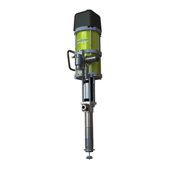
Page 17: Available Configurations
Available Configurations 4 Available Configurations Rexson part numbers of High viscosity pumps Presentation of the pump REXSON SH930 A very versatile pump, the REXSON SH930 hydraulic is used for airless applications as well as for the extrusion of thick products (>50000 cP*). Different configurations are available. - Page 18 Available Configurations 4.2 Table 1 Fluid section-Air motor selection Available Motors Pressure Maximum Air Inlet Maximum Outlet Documentation Ratio Pressure Fluid Pressure reference NONE MOTOR 60 : 1 5200 582128110 9200-2 R E X 0930 4.3 Table 2 Fluid section – Pump foot & Material selection Available material Available pump foot Stainless steels...
-
Page 19: Identification
Identification 5 Identification 5.1 Description of the marking of the plate Principles This equipment complies with the following provisions: Machinery Directive (2006/42 / EC), Safety of machinery - Basic terms, general implementation guidelines DIN EN ISO 12100 T1/T2 ... - Page 20 Identification Description SAMES KREMLIN Manufacturer's mark STAINS FRANCE POMPE / PUMP Pump reference and serial number. The first two digits indicate the year of manufacture. REF / SERIE PROD Maximum product pressure (Bar/Psi) MAX. PRES. (Bar/Psi) Maximum air pressure (Bar/Psi)
-
Page 21: Correspondence Table New Part Numbers / Significant Designations
Identification 5.2 Correspondence table new part numbers / Significant designations New part numbers Significant designations 62 57 0930 M S F 000 REXSH0930-MO-MA-FO-SE Options Motor MOT9200-2 Material Stainless Steel + Carbide valves Seal Foot Follower plate Ø 105 mm Plain cylinder Ø 112 mm Documentation Reference Air Motor 9200-2 582128110... -
Page 22: Technical Characteristics
Technical characteristics 6 Technical characteristics 6.1 General characteristics Technical characteristics Volume per 930 cm cycle 31,54 oz Stroke 205 mm / 8,07 in Fluid outlet 1" 1/2 connection F BSPP Weight 100 kg / 220,5 lb Maximum fluid 80°C / 176°F temperature Wetted parts Depending on... - Page 23 Technical characteristics (General characteristics - continued) Pump foot Technical characteristic Follower Plate Ø 105 mm Plain Cylinder Ø 112 mm Materials of construction Stainless steel Pump body Wet Cup Stainless steel Upper body Stainless steel Cylinder Stainless steel chromed Piston Piston rod Stainless steel chromed (Upper check)
-
Page 24: Principle Of Operation
Technical characteristics 6.2 Principle of operation Expected use These pumps coupled to air or hydraulic motors are intended for transferring, or spraying different liquid or pasty products with a desired flow rate and output pressure. Functional description When the piston (1) rises, the upper ball check (2) closes, the lower check valve (3) opens and the shovel valve (4) closes. - Page 25 Technical characteristics ATTENTION! The friction generated by the movement of the product inside the pump and its accessories, as well as that caused by the seals, creates static electricity that can cause fire or explosion. Therefore, the fluid section system must be earthed via the motor ground cable (see the motor instruction manual for its ground connection).
-
Page 26: Installation
(pneumatic or hydraulic) with compatible stroke. It is imperative to comply with an air motor / hydraulic combination provided by SAMES KREMLIN Make sure that all connections of the pump and fluid section components - cables, hoses and pipes - are installed in such a way that they do not cause people to fall. -
Page 27: Storage
Installation 7.2.2 Air supply connection Ensure that in bound air supply and hose are of correct size to reduce pressure fluctuations and pressure drops. 7.3 Storage Pump Place the equipment away from moisture after closing the various air inlets and various openings (plugs). Storage before installation: ... -
Page 28: Commissioning
Commissioning 8 Commissioning The fluid sections are integrated in a system, if necessary refer to any additional instructions for further information on commissioning. Pump Pumps are tested for operation at the factory using a light weight oil lubricant. Before commissioning, this lubricant must be removed by flushing with a suitable solvent. -
Page 29: Use Of The Product
Use of the product 9 Use of the product 9.1 User settings Wet Cup Before commissioning, fill the wet cup halfway with lubricant "T". The wetting cup nut must be tightened moderately. Overtightening quickly damages the gland packing. A wrench is supplied to allow proper tightening. -
Page 30: Safety In Production
Use of the product 9.2 Safety in production Guards (motor cover, coupling guard, housings, ...) are set up for safe use of the equipment. The manufacturer can not be held responsible in case of bodily injury as well as breakdowns and / or damage of the material resulting from the destruction, the occultation or the total or partial removal of the protectors. -
Page 31: Shutdown Procedure
Use of the product 9.4 Shutdown procedure Pump To avoid the risk of personal injury, material injections, injuries caused by moving parts or electric arcs, it is imperative that the following procedure be followed before any work is carried out when shutting down the system, assembling, cleaning or changing the nozzle. -
Page 32: Diagnostic Help / Troubleshooting Guide
Use of the product 9.5 Diagnostic help / Troubleshooting guide Possible symptoms of faults / Causes of faults / Remedies to apply Defaults Possible causes Remedies Leakage at the cup seals Insufficient tightening of the Tighten the cup. packing nut Incorrect assembly of seals Check the assembly. - Page 33 Use of the product Defaults Possible causes Remedies Pump strokes quickly Bad feeding of the pump. Check parameters downward (simple effect accessories (pressure follower working) plate or suction rod …). Accessories can be not adapted or clogged. Product is too viscous. Bad definition of the pump.
-
Page 34: Maintenance
These procedures cover only the most common problems. If the information given here does not solve the problem you are experiencing, please contact your local SAMES KREMLIN representative for assistance. During prolonged shutdown, stop the pump when the piston is in the low position. -
Page 35: Preventive Maintenance Plan
Maintenance 10.1 Preventive Maintenance Plan ATTENTION Before pump maintenance service work performed imperative follow depressurization procedure and the safety instructions. Routine maintenance after certain number operating hours is recommended. This is defined by the service department of the user and depends on the product, the working cycle and the usual pressure. -
Page 36: General Preconisation Maintenance
Maintenance 10.2 General preconisation maintenance ATTENTION Before pump maintenance service work performed imperative follow depressurization procedure and the safety instructions. Before each reassembly Clean the parts with the appropriate cleaning solvent. Fit new seals if necessary, after greasing them. ... -
Page 37: Disassembly / Reassembly Operation
Disassembly / Reassembly Operation 11 Disassembly / Reassembly Operation ATTENTION Before pump maintenance service work performed imperative follow depressurization procedure and the safety instructions. ATTENTION The equipment is subject to the ATEX directive and must not be modified under any circumstances. Failure to comply with this recommendation does not engage our responsibility. - Page 38 Disassembly / Reassembly Operation Fluid Section wall mounted & Plain Cylinder REXSH930---FP- REXSH930---PC- (For a full description of spare parts, see Part 12 - Spare Parts)
- Page 39 Disassembly / Reassembly Operation (For a full description of spare parts, see Part 12 - Spare Parts)
-
Page 40: Disassembly Of The Pump
Disassembly / Reassembly Operation Disassembly of the pump Lift up the pump using a bridge or a stem,... - Page 41 Disassembly / Reassembly Operation Unscrew the screw (1), Rotate the protection (2).
- Page 42 Disassembly / Reassembly Operation REMOVE THE LUBRICANT Using a flat screwdriver, disengage the axle brake (1) from the groove above the locking ring (2), in order to release it. Manually lift the locking ring (3) and manually remove the coupling nuts (4) underneath.
- Page 43 Disassembly / Reassembly Operation Unscrew the 4 nuts (1), Put aside the protection (3) and the fluid section (4),...
- Page 44 Disassembly / Reassembly Operation Remove the axle brake (1) and the locking ring (2), Remove the 4 tie rods (3) with a 20 mm wrench...
-
Page 45: Iso Flansh Flange
Disassembly / Reassembly Operation ISO FLANSH flange Unscrew the 4 screws (1), Remove the ISO FLANSH flange (2), Remove the seal (3), Replace and grease a new seal (3), Place the ISO FLANSH flange (2), ... -
Page 46: Disassembly
Disassembly / Reassembly Operation Disassembly Unsrew the nut (1), take off the washer (2), Take off the shovel (3), the closing washer (4) and the shovel spacer (5), For the pump model REXSH0930- -FP- only : ... - Page 47 Disassembly / Reassembly Operation Unscrew the filling tube (1) with the wrench, Take off the seat (2), and the 2 seals (3), Unscrew the lower valve (4) with 2 wrenches, Take off the first “M” washer, the cup spacer, the seals, the second “M”...
- Page 48 Disassembly / Reassembly Operation Unscrew the valve body (1) with the wrench, Take off the first seal (2), Loosen the wetting cup (3) with the cup wrench, Take off the piston assembly (4), the piston seat assembly (5), and the shovel rod (6),...
- Page 49 Disassembly / Reassembly Operation Remove the pin (1) with a pin driver ø 5 mm, Unscrew and take off the shovel rod (2),...
- Page 50 Disassembly / Reassembly Operation Unscrew the piston seat assembly (1), Take off the seals (2 & 3), Take off the “M”washer (4), Take off the ball (5) and the “F” washer (6),...
- Page 51 Disassembly / Reassembly Operation Unscrew the cylinder (1) with the wrench, Take off the second seal (2), Unscrew the wetting cup (3) with the cup wrench, Unscew the 12 screws (4), Place 4 screws (4) into the 4 little holes of the cartridge (5),...
- Page 52 Disassembly / Reassembly Operation Screw the 4 screws (1) to remove the cartridge (2), Remove the cartridge (3) and unscrew the 4 screws (4), Take off the “M” washer (5), Take off the “F” washer (6), ...
-
Page 53: Re-Assembly
Disassembly / Reassembly Operation Re-assembly Place the upper flange (1) in a vice, Grease the seat (2), Place the ball (3) on the seat (2), Place the “M”washer (4), Grease and place the seals (5 & 6) between the “M” washer (4) and the “F”... - Page 54 Disassembly / Reassembly Operation GREASE GREASE Grease the piston (1) and the cylinder (2), Put the piston assembly (1) into the cylinder (2), Grease and place the seal (3), between the cylinder (4) and the upper flange (5), ...
- Page 55 Disassembly / Reassembly Operation Tighten the piston assembly (1) / seat assembly (2), Grease inside the cartridge (3), Grease the seal (4), and put it onto the cartridge (3) Grease the “F” washer (5), the seal (6), the seals (7), the cup block (8), and the “M”...
- Page 56 Disassembly / Reassembly Operation Place and screw the 12 screws (1) onto the cartridge (2) to the torque of 20 N.m., Grease the wetting-cup (3) and screw it into the cartridge (2), Glue (loctite 5572) and screw the shovel rod (4) into the piston seat (5), ...
- Page 57 Disassembly / Reassembly Operation Grease the cylinder (1), the shovel rod (2) and the seal (3), Place the seal (3) in the valve body (4) then place it onto the cylinder (1), Tighten the valve body (4), ...
- Page 58 Disassembly / Reassembly Operation Insert this assembly (1) into the shovel rod (2), and tighten the cup (3), Grease the seals (4), Insert the first seal (4) into the valve body (5), Place the seat (6) and the second seal (4), ...
- Page 59 Disassembly / Reassembly Operation Before each reassembly Clean the parts with the appropriate cleaning solvent. Fit new seals if necessary, after greasing them. Grease the piston and the inside of the cylinder to avoid damaging the seals. ...
-
Page 60: Spare Parts
Spare parts 12 Spare parts Use only genuine SAMES KREMLIN accessories and spare parts designed to withstand the pump's operating pressures. Fluid Section wall mounted & Plain Cylinder REXSH930---FP- REXSH930---PC- WARNING: these parts are not supplied with the fluid section alone as they... - Page 61 Spare parts...
-
Page 62: Parts
Spare parts Parts REXSH0930 - - - Follower Plate Plain Cylinder Description # Ref. Spare part maintenance level** Upper flange Fluid flange 144 250 001 Cartridge assembly 144 250 096 Cartridge 211 562 Screw, CHc M 8x20 930 151 279 ... - Page 63 Spare parts Ind 52 Ind 53 REXSH0930 - - - Follower Plate Plain Cylinder Ind. Description # Ref. Spare part maintenance level** 144 250 195 M washer 211 333 Cup spacer F 60 220 Lower valve 144 250 196 Seal, FKM 909 420 509...
-
Page 64: Lower Adapter Flange
Spare parts Lower adapter flange Spare part Ind. Description # Ref. maintenance level** 4 tie rods flange 144 245 495 **55 Protective housing N.S. (051 150 110) **56 N.S. (051 150 101) Tie-rod * Recommended maintenance parts. N S: Denotes parts are not serviceable. **Level 1 : Preventive maintenance Level 2 : Corrective Level 3 : Exceptional... -
Page 65: Recommended Seals Pack
Spare parts Recommended Seals pack Code Composition PU + PTFEV Mastics - PVC – Butyl with a better temperature resistance * Allows a better mechanical resistance é Accessory Ind. Description # Ref. Bottle of lubricant T (125 ml / 0,034 oz) 149 990 020... -
Page 66: Seals Pack Composition: 06
Spare parts Seals pack composition: 06 Seals pack: 144 251 196 Ind. Description Material Cup block 210 724 ST STEEL 84 395 Cup packing 210 722 Seal 84 456 210 726 Piston packing 211 318 PTFEV 211 334 Shovel packing 211 335 PTFE O ring...
Need help?
Do you have a question about the REX SH0930 and is the answer not in the manual?
Questions and answers