Table of Contents
Advertisement
Quick Links
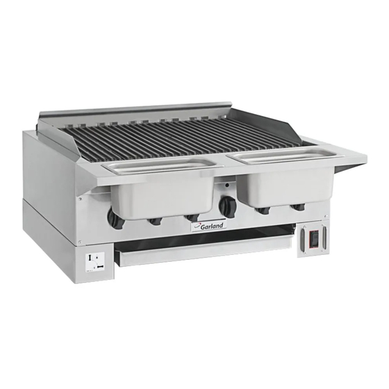
SERVICE MANUAL
High Effi ciency Radiant Char-Broiler
models
HEEGM24CL
HEEGM36CL
HEEGM48CL
HEEGM60CL
Please read all sections of this manual and retain for future
reference.
This manual is written for the specific model(s) listed on the
i
front cover. Unless specified, this manual should not be used for
any other make or model of appliance.
Garland reserves the right to change product specifications
i
without notices and accepts no liability for any inaccuracies,
errors or omissions contained herein.
Garland Commercial Ranges, Ltd.
1177 Kamato Road, Mississauga,
Ontario, CANADA L4W 1X4
Part # 4532502 Rev 0 (01-Aug-13)
T. 1-905-624-0260
USA Sales, Parts and Service 1-800-424-2411
F. 1-905-624-5669
Canadian Sales 1-888-442-7526
www.garland-group.com
Canada or USA Parts/Service 1-800-427-6668
© 2013 Garland Commercial Ranges Limited
Advertisement
Table of Contents
Troubleshooting

Subscribe to Our Youtube Channel
Related Manuals for Garland HEEGM48CL


Summary of Contents for Garland HEEGM48CL
- Page 1 Unless specified, this manual should not be used for any other make or model of appliance. Garland reserves the right to change product specifications without notices and accepts no liability for any inaccuracies, errors or omissions contained herein.
- Page 2 SAFETY ALERT SYMBOLS The following safety alert symbols and signal words indicate important safety information throughout this book. Read all safety messages carefully and implement relevant safety precautions at all times. This safety symbol alerts you to a hazardous situation that WILL or COULD cause serious bodily harm or death.
-
Page 3: Table Of Contents
HEEGM48CL 120VAC ........ -
Page 4: Safety Requirements
IMPORTANT Garland / U.S. Range products are not approved or authorized for home or residential use, but are intended for commercial applications only. Garland / U.S. Range will not provide service, warranty, maintenance or support of any kind other than in commercial applications. - Page 5 For a list of Garland authorized service agents, please refer to the Garland web site @www.Garland-Group.com. IMPORTANT In the United States, installation of this appliance must conform to the National Fuel Gas Code ANSI Z223.1, or latest edition, NFPA No.54 –...
-
Page 6: Rating Plate, Serial#, Model# Information
Model code can be found on the rating plate. Four HEEGM models are available: • HEEGM24CL - 24” (610mm) • HEEGM36CL - 34” (864mm) • HEEGM48CL - 48” (1219mm) • HEEGM60CL - 58” (1473mm) Page 6 | HEEGM Service Manual part# 4532502 (Rev 0) -
Page 7: Technical Specifications
Propane (total BTU)* No. Of Burners HEEGM24CL 58,000 52,000 HEEGM36CL 87,000 78,000 HEEGM48CL 130,500 117,000 HEEGM60CL 159,500 143,000 *Total BTU data is based on the manifold operating pressure specified below, in section 3.2, and applies to installations up to 2000ft (610m). -
Page 8: Unit Configuration
You will find all the major components illustrated in this section. For a list of parts and part numbers, please refer to the HEEGM Parts List (see section “8 Related Documents”), available on our website @ www.Garland-Group.com 4.1 Important Features The features listed below are referenced in the illustrations in “4.1.2 Major Components”. -
Page 9: Major Components Illustrated
4 UNIT CONFIGURATION (CONT.) 4.3 Major Components Illustrated Solenoid Gas Valve x2 for 24”/ 36” model x4 for 48”/ 60” model Radiant Main Power Supply Gas Pressure Burner Panel Removed (120V Only) Regulator Side Manifold x1 for 24”/ 36” model x2 for 48”/ 60”... -
Page 10: Troubleshooting Guide
5 TROUBLESHOOTING GUIDE 5.1 Sequence of Operation This section helps you to get familiar with the mechanical and electrical controls, and the operations of the HEEGM broiler. For a comprehensive overview of the HEEGM operation, please use this section together with the Wiring Diagrams in section “7 Wiring Diagrams”. To find out where the major components are installed, see “4.1.2 Major Components”. - Page 11 5 TROUBLE SHOOTING GUIDE (CONT.) Operation Sequence Illustrated - HEEGM24CL, HEEGM36CL The illustrations below provide simplified views of the relationships among the major components: ignition modules, electrodes, solenoid vales, manifolds, switches, and burners. HEEGM24CL Top View of Burners Burner# Burners ON/OFF Switch Transformer HEEGM36CL...
- Page 12 5 TROUBLE SHOOTING GUIDE (CONT.) Operation Sequence Illustrated (cont.) - HEEGM48CL, HEEGM60CL HEEGM48CL Burners 1-4 Controls Top View of Burners Burners 5-9 Controls Modules Burner# Right Switch Switch Transformer Main Power (240V Only) ON/OFF Switch (240V Only) HEEGM60CL Burners 1-6 Controls...
-
Page 13: Troubleshooting Flowchart
5 TROUBLE SHOOTING GUIDE (CONT.) 5.2 Troubleshooting Flowchart Start 240V Turn on main power switch Is main power Ensure power is switch light supplied to the unit Start 120V Turn on switch 120V 240V Check Is switch Replace Replace main switch light on? transformer... -
Page 14: Problems & Evaluation
5 TROUBLE SHOOTING GUIDE (CONT.) 5.3 Problems & Evaluation The following table describes a number of common symptoms and possible causes. Use this table together with section 5.2 Troubleshooting Flowchart for problem analysis. SYMPTOM POSSIBLE CAUSE EVALUATION May need to adjust burner air Not enough air mixing with gas. - Page 15 5 TROUBLE SHOOTING GUIDE (CONT.) 5.3 Problems & Evaluation (cont.) SYMPTOM POSSIBLE CAUSE EVALUATION Inspect ignitor and check spark Damaged spark ignitor. gap for min 0.125”(1/8”) - max Weak ignition sparks 0.160”(5/32”) opening. Ignition Module Problem. Replace Module Page 15 | HEEGM Service Manual part# 4532502 (Rev 0)
-
Page 16: Remove, Install And Adjust Components
6 REMOVE, INSTALL AND ADJUST COMPONENTS 6.1 Knob Each knob is connected to the gas valve extension Valve Extension and is secured with a set screw on the left side. Use a flat screwdriver to loosen or tighten the set screw. -
Page 17: Side Leg Panels - Left / Right
6 COMPONENTS (CONT.) 6.3 Side Leg Panels - Left / Right Remove the side leg panels to gain access to: • switch(es), wiring, and ignition module(s) (R-SIDE) • transformer and terminal block (240V unit) (R-SIDE) • wire connections to main power (R-SIDE) •... -
Page 18: Gas Pressure Regulator & Gas Pressure
6 COMPONENTS (CONT.) 6.4 Gas Pressure Regulator & Gas Pressure 6.4.1 General Information Gas pressure regulators have two main Basics Of A Gas Pressure Regulator purposes: to reduce supply main pressure to safe Removable Seal Cap operating pressures of connected appliances; Adjustment (Screw) and to maintain constant downstream pressure, Atmospheric... - Page 19 6 COMPONENTS (CONT.) To check manifold pressure and adjust regulator IMPORTANT When adjusting gas pressure, all gas utilizing equipment should be on during adjustments. This will ensure burners are getting correct gas pressures during a system load. FOR HEEGM 24” & 36” UNITS 1.
-
Page 20: Burner And Air Shutter
6 COMPONENTS (CONT.) 6.5 Burner and Air Shutter The HEEGM broiler is made up of long gas burners with various sized ports, covered by cast iron radiants. Stainless steel air baffles are anchored to the bottom of the burners with cotter pins. See section “4 Unit Configuration”. - Page 21 6 COMPONENTS (CONT.) 6.5.3 Flame and Air Shutter Adjustment Inspect the flame of each burner to determine whether adjustments to the burner air shutter are necessary. Adjust an air shutter if: • the tips of the flame appear too yellow. The shutter should be turned to allow MORE air to enter the burner cavity.
-
Page 22: Gas Valve
6 COMPONENTS (CONT.) 6.6 Gas Valve HEEGM__CL models use non-adjustable control valves to regulate the flow of gas to the burners. These valves are fixed (no center stem adjustment). 6.6.1 Inspecting a Gas Valve A damaged, fractured, seized, or restricted valve may result in delayed ignition or may prevent the burner from lighting at all. -
Page 23: Orifice
6 COMPONENTS (CONT.) 5. Remove the valve from the manifold by spinning the valve counter-clockwise. DO NOT spin by the valve stem. Use a wrench on the valve body. 6. Remove the orifice and install it on the new gas valve using suitable pipe sealant. 7. -
Page 24: Electrode
6 COMPONENTS (CONT.) 6.8 Electrode All burners are equipped with continuous electronic spark electrodes to ensure flame is on at all times during operation. Continuous sparking is intended to remain energized until its corresponding ignition control module senses flame current. Electrical spark generation is then shut off until flame current is no longer sensed. - Page 25 6 COMPONENTS (CONT.) 5. Push the orange silicone sleeve down to expose the electrodes. . When replacing electrodes on the far left or far right of the unit, you may need to remove screws holding the wire channel to access the electrode screws. 6.
-
Page 26: Solenoid Valve
6 COMPONENTS (CONT.) 6.9 Solenoid Valve 6.9.1 Specification • Electrical Rating: 120VAC, 50/60Hz, 0.088A • Power: 10.5VA per Coil • Permissible Ambient (Surface) Temperature: -20 deg F to 280 deg F (-29 to 138 deg C) • Gas Connection: 1/2 NPT Inlet x 1/2 NPT Outlet •... - Page 27 6 COMPONENTS (CONT.) FOR A 24” OR 36” UNIT — To replace a solenoid valve: A 24” or 36” unit has only ONE side manifold in the LEFT LEG and ONE Front Manifold. DANGER: Turn off gas supply and remove main power supply to the unit. 2.
- Page 28 6 COMPONENTS (CONT.) FOR A 48” OR 60” UNIT — To replace a solenoid valve: A 48” or 60” unit has TWO side manifolds in the LEFT LEG and TWO front gas pipes. Please refer to “5.1 Sequence of Operation” and “7 Wiring Diagrams”. To replace a solenoid valve connected to the INNER SIDE manifold: DANGER: Turn off gas supply and remove main power supply to the unit.
- Page 29 6 COMPONENTS (CONT.) To replace a solenoid valve connected to the OUTER SIDE manifold DANGER: Turn off gas supply and remove main power supply to the unit. 2. Remove the Left Side Leg Panel, Knobs and Valve Panel (see sections 6.1, 6.2, and 6.3). 3.
-
Page 30: Ignition Module
6 COMPONENTS (CONT.) 6.10 Ignition Module Depending on the model, you will find a 4-spark, a 6-spark, or both types of ignition modules installed in the Right Leg of the broiler. When energized, the module sparks continuously until flame is sensed. 6.10.1 Specification •... -
Page 31: On-Off Switch & Main Power Switch
6 COMPONENTS (CONT.) 6.11 ON-OFF Switch & Main Power Switch WARNING Before working on the switch, remove the unit from power supply. IMPORTANT The redundant terminals on the switch(es) protect the spade connectors. When installing a new switch, put on new redundant terminals or re-use the existing ones. -
Page 32: Transformer
6 COMPONENTS (CONT.) 6.12 Transformer For a 240V unit, a transformer is installed inside the Right Leg. 6.12.1 Specification • 100VA, 50/60Hz • Primary 240V; Secondary, 120V IMPORTANT Input and Output on transformer are defined and must be observed. IMPORTANT The arrangement of links are critical and shouldn’t be altered. - Page 33 6 COMPONENTS (CONT.) 6.12.3 Remove or Install a Transformer HIGH VOLTAGE WARNING Risk of an electric shock. Disconnect power supply to the unit and allow the unit to cool down. To replace a transformer: WARNING: Disconnect power supply to the broiler and allow the unit to cool down. 2.
-
Page 34: Wiring Diagrams
HEEGM24CL 120VAC 7 WIRING DIAGRAMS Page 34 | HEEGM Service Manual part# 4532502 (Rev 0) -
Page 35: Heegm24Cl 240Vac
HEEGM24CL 240VAC 7 WIRING DIAGRAMS (CONT.) Page 35 | HEEGM Service Manual part# 4532502 (Rev 0) -
Page 36: Heegm36Cl 120Vac
HEEGM36CL 120VAC 7 WIRING DIAGRAMS (CONT.) Page 36 | HEEGM Service Manual part# 4532502 (Rev 0) -
Page 37: Heegm36Cl 240Vac
HEEGM36CL 240VAC 7 WIRING DIAGRAMS (CONT.) Page 37 | HEEGM Service Manual part# 4532502 (Rev 0) -
Page 38: Heegm48Cl 120Vac
HEEGM48CL 120VAC 7 WIRING DIAGRAMS (CONT.) Page 38 | HEEGM Service Manual part# 4532502 (Rev 0) -
Page 39: Heegm48Cl 240Vac
HEEGM48CL 240VAC 7 WIRING DIAGRAMS (CONT.) Page 39 | HEEGM Service Manual part# 4532502 (Rev 0) -
Page 40: Heegm60Cl 120Vac
HEEGM60CL 120VAC 7 WIRING DIAGRAMS (CONT.) Page 40 | HEEGM Service Manual part# 4532502 (Rev 0) -
Page 41: Heegm60Cl 240Vac
HEEGM60CL 240VAC 7 WIRING DIAGRAMS (CONT.) Page 41 | HEEGM Service Manual part# 4532502 (Rev 0) -
Page 42: Related Documents & Revision History
8 RELATED DOCUMENTS & REVISION HISTORY Related Documents Part# or Filename Document 4530868 Installation and Operation Manual G_GC_PL_HEBROILERS_HEEGM Parts List G_GC_SS_HEBROILER_HEEGM-24-36-48-60 Specification Sheet - HEEGM G_GC_SS_EQUIPMENTSTAND_HEMST Specification Sheet - HEMST Series Equipment Stands Revision History Rev# Section Notes Date New Release 01-Aug-13 Page 42 | HEEGM Service Manual part# 4532502 (Rev 0) - Page 44 Service Manual GARLAND High Efficiency Radiant Char Broiler HEEGM Garland Commercial Ranges, Ltd. T. 1-905-624-0260 USA Sales, Parts and Service 1-800-424-2411 1177 Kamato Road, Mississauga, F. 1-905-624-5669 Canadian Sales 1-888-442-7526 Ontario, CANADA L4W 1X4 www.garland-group.com Canada or USA Parts/Service 1-800-427-6668...
Need help?
Do you have a question about the HEEGM48CL and is the answer not in the manual?
Questions and answers