Table of Contents
Advertisement
Quick Links
UM3312
User manual
Stepper motor driver evaluation board based on the L6470
Introduction
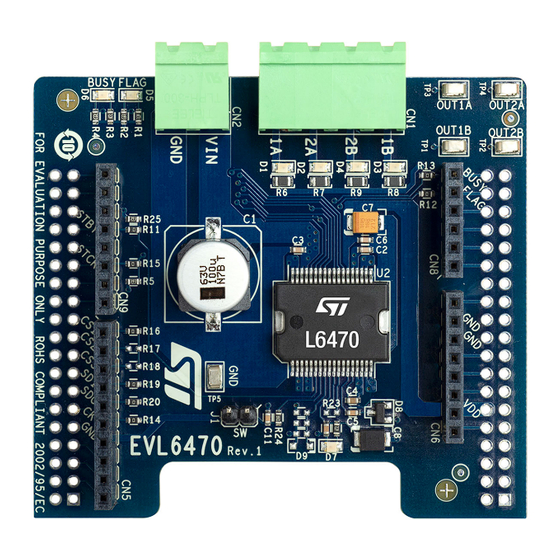
The
EVL6470
is a stepper motor driver evaluation board based on the L6470.
It provides an affordable and easy-to-use solution to drive a stepper motor in your application.
The L6470 device, created using analog mixed signal technology, is an advanced, fully integrated, solution suitable for driving
two-phase bipolar stepper motors with microstepping. It integrates a dual low R
DMOS full bridge with an accurate on-chip
dsON
current sensing circuitry suitable for non-dissipative current control and overcurrent protection. Thanks to a unique control
system, a true 1/128 step resolution is achieved. The digital control core can generate user-defined motion profiles with
acceleration, deceleration, speed, or target position, which are easily programmed through a dedicated set of registers. All
commands and data registers, including those used to set analog values (that is: current control value, current protection trip
point, dead time, PWM frequency, etc.) are sent through a standard 5-Mbit/s SPI. A complete set of protections (thermal, low
bus voltage, overcurrent, and motor stall) makes the L6470 device fully protected, as required by the most demanding motor
control applications.
The EVL6470 is compatible with the Arduino® UNO R3 connector and supports the addition of other boards, which can be
stacked to drive up to three stepper motors.
Figure 1.
EVL6470 board
UM3312 - Rev 1 - March 2024
www.st.com
For further information contact your local STMicroelectronics sales office.
Advertisement
Table of Contents

Related Manuals for ST EVL6470


Summary of Contents for ST EVL6470
- Page 1 L6470 device fully protected, as required by the most demanding motor control applications. The EVL6470 is compatible with the Arduino® UNO R3 connector and supports the addition of other boards, which can be stacked to drive up to three stepper motors.
-
Page 2: Getting Started
UM3312 Getting started Getting started The EVL6470 evaluation board is a stepper motor driver covering a wide range of applications. The maximum ratings are: • Power stage supply voltage (VS) from 8 V to 45 V • Motor phase current up to 3 A... -
Page 3: Hardware Description And Configuration
UM3312 Hardware description andconfiguration Hardware description and configuration Figure 2. EVL6470 board overview Arduino Uno R3 connector Arduino Uno R3 connector Motor phases connector Power-up LED External switch connector R16, R17, R18 Power connector Chip select SPI lines Status flag LED... -
Page 4: Selecting The Chip Select Line Of The Spi
An external switch can be connected to J1 to stop the motor movement when the switch status changes. For proper management of this additional feature of the L6470 device, refer to section “External switch (SW pin)” of the related datasheet (see www.st.com). UM3312 - Rev 1... -
Page 5: Safety Precautions
UM3312 Safety precautions Safety precautions Warning: Some of the components mounted on the board could reach hazardous temperatures during operation. While using the board, the following precautions must be observed: • Do not touch the components or the heatsink. • Do not cover the board. -
Page 6: Bill Of Material
UM3312 Bill of material Bill of material Table 3. EVL6470 bill of material Item Q.ty Ref. Part/Value Description Manufact. Order code Connector 5.08mm 691312510004 CON-1x4 Wurth Elektronik Close vertical or equivalent Connector 5.08mm 691312510002 CON-1x2 Wurth Elektronik Close vertical or equivalent... - Page 7 UM3312 Bill of material Item Q.ty Ref. Part/Value Description Manufact. Order code Connector 5.08mm 691351500004 horizontal with CON-1x4 Wurth Elektronik or equivalent hook on wire side Connector 5.08mm 691351500002 horizontal with CON-1x2 Wurth Elektronik or equivalent hook on wire side UM3312 - Rev 1 page 7/13...
-
Page 8: Schematic Diagram
UM3312 Schematic diagram Schematic diagram Figure 3. EVL6470 schematic diagram IOREF 3.3V 330R GREEN 220NF CON-1x8 47UF 100NF S TRIP 254P -F-8 BAR43 CON-2x19 8-45V FLAG BUSY_SYNC R12 0R R13 0R 100NF 10NF TP 5 10UF CON-1x6 S TRIP 254P -F-6... -
Page 9: Revision History
UM3312 Revision history Table 4. Document revision history Date Version Changes 18-Mar-2024 Initial release. UM3312 - Rev 1 page 9/13... -
Page 10: Table Of Contents
UM3312 Contents Contents Getting started ..............2 Hardware description and configuration . -
Page 11: List Of Tables
EVL6470 bill of material ........ -
Page 12: List Of Figures
EVL6470 schematic diagram ........ - Page 13 ST’s terms and conditions of sale in place at the time of order acknowledgment. Purchasers are solely responsible for the choice, selection, and use of ST products and ST assumes no liability for application assistance or the design of purchasers’...
Need help?
Do you have a question about the EVL6470 and is the answer not in the manual?
Questions and answers