Table of Contents
Advertisement
Quick Links
Advertisement
Chapters
Table of Contents

Related Manuals for Minolta Di470


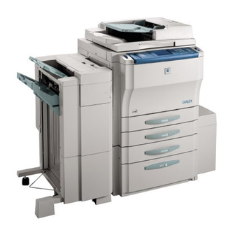
Summary of Contents for Minolta Di470
- Page 1 Return to SubMenu Service Manual Di470 [General]...
- Page 2 The Optional Accessories used with the Di470 are common with the Di450/Di550. Please refer to Di450/Di550 Option Service Manual for the Di470 Acces- sories.
- Page 4 INDEX (GENERAL) GENERAL MECHANICAL/ELECTRICAL...
- Page 6 GENERAL...
-
Page 8: Table Of Contents
CONTENTS 1. SPECIFICATION ..................... G-1 2. PRECAUTIONS FOR INSTALLATION ............G-4 2-1. Installation Site ..................G-4 2-2. Power Source ..................G-4 2-3. Grounding ....................G-4 3. PRECAUTIONS FOR USE ................G-5 3-1. To ensure that the copier is used in an optimum condition ..... G-5 3-2. -
Page 10: Specification
SPECIFICATION TYPE Console ORIGINAL SCANNING SYSTEM Lens Reduction Type CCD Line Sensor PHOTOCONDUCTOR Organic Photoconductor COPYING SYSTEM Electrostatic Dry Powdered Image Transfer to Plain Paper RESOLUTION 600 dpi × 600 dpi PAPER FEEDING SYSTEM 4-Way system (for U.S.A) Multi Bypass Table: 50 sheets of paper 1st Drawer (Universal): 550 sheets of paper 2nd Drawer (Universal): 550 sheets of paper 3rd Drawer: 2600 sheets of paper... - Page 11 ❍ COPY MEDIUM : Permissible -: Not permissible C: Crosswise Multi 1st to 2nd 4WAY 5WAY Paper Source Bypass Duplex Drawer (LCC) (3rd to 4th) Table Plain paper ❍ ❍ ❍ ❍ ❍ (60 to 90 g/m Translucent ❍ *1 –...
- Page 12 ZOOM RATIOS Area Mode Metric Inch ×1.000 ×1.000 Full Size ×0.785 ×0.816 ×0.733 ×0.707 Reduction ×0.647 ×0.500 Fixed ×0.500 ×1.214 ×1.154 ×1.294 ×1.414 Enlargement ×1.545 ×2.000 ×2.000 Variable 25 % to 400 % (in 0.1 % increments) LENS Through Lens (F = 4.0, f = 62 mm) EXPOSURE LAMP Rare Gas Fluorescent Light (20 W) FUSING TEMPERATURE...
-
Page 13: Precautions For Installation
PRECAUTIONS FOR INSTALLATION 2-1. Installation Site To ensure safety and utmost performance of the copier, the copier should NOT be used in a place: • Where it will be subjected to extremely high or low temperature or humidity. • Where it will be subjected to sudden fluctuations in either temperature or humidity. •... -
Page 14: Precautions For Use
PRECAUTIONS FOR USE 3-1. To ensure that the copier is used in an optimum condition • Never place a heavy object on the copier or subject the copier to shocks. • Insert the power plug all the way into the outlet. •... -
Page 15: Handling Of Consumables
HANDLING OF CONSUMABLES Before using any consumables, always read the label on its container carefully. • Paper can be easily damaged by dampness. To prevent absorption of moisture, store paper, which has been removed from its wrapper but not loaded in the drawer, in a sealed plastic bag in a cool, dark place. -
Page 16: System Options
SYSTEM OPTIONS 4002G508AA 1145M035AA 4002G507AA 4002G506AA 4002G504AA 4002G502AA 4002G501AA 4002O101AA 4002G511AA 4002G503AA 3, 4 4002G505AA 4002O102AA 4002G509AA 1. Copier 9. Large Capacity Cassette C-306 2. 2 Way Paper Feed Cabinet PF-208 10. Large Capacity Cassette C-306L 3. Large Capacity Cassette PF-115 11. - Page 18 MECHANICAL/ ELECTRICAL...
- Page 20 CONTENTS 1. CROSS SECTIONAL VIEW ................M-1 2. COPY PROCESS .................... M-2 3. DRIVE SYSTEM ....................M-4 4. SEQUENTIAL EXPLANATION ................ M-5 5. IMAGE STABILIZATION SYSTEM ..............M-6 5-1. AIDC Sensor .................... M-7 5-2. Image Stabilization System Control ............M-8 6.
- Page 21 12-13.Sub Hopper Toner Empty Detecting Mechanism ........M-44 13. PAPER TAKE UP/FEED SECTION ..............M-45 13-1.Drawer In Position Detection ..............M-46 13-2.Paper Empty Detection Mechanism ............M-47 13-3.Drawer Paper Lifting/Lowering Mechanism ..........M-48 13-4.Paper Level Detection Mechanism ............M-50 13-5.Universal Tray Paper Size Detection Mechanism ........M-51 13-6.Paper Take Up Mechanism ..............
- Page 22 22-3.Turnover Roller Separation Control ............M-82 22-4.Turnover/Exit Mechanism ................ M-83 (1) Selection of Turnover or Exit Path ........... M-83 (2) Path for Accommodating Paper Longer Than A4L ......M-83 23. OTHER MECHANISM ..................M-84 23-1.Memory Backup ..................M-84 23-2.Flash Memory ..................M-85 23-3.Dehumidifying Mechanism ..............
-
Page 24: Cross Sectional View
CROSS SECTIONAL VIEW 4002M501AA 1. Fusing Section 4. Developing Section 2. IR Section 5. Paper Tray 3. PH Section 6. Exit/Turnover Section... -
Page 25: Copy Process
COPY PROCESS 4. IR Image- 6. PH Image- 3. Photoelectric 5. Memory Processing Conversion Processing 7. Laser 2. Drum Exposure Charging 14. Main Erase 13. Cleaning 1. PC Drum 8. Developing 11. Image 10. Bypass 17. Exit/Turnover 12. Paper 16. Fusing 15. - Page 26 10. Bypass Paper Feeding • Paper is fed from the Bypass Table. 11. Image Transfer • A DC positive corona emission is applied to the back side of the paper, thereby attracting toner onto the surface of the paper. 12. Paper Separation •...
-
Page 27: Drive System
DRIVE SYSTEM connect 4002M503AA 1. Fusing Motor (M2) 8. 1st Drawer Lift-Up Motor (M11) 2. PC Drum Drive Motor (M21) 9. 2nd Drawer Lift-Up Motor (M12) 3. Scanner Motor (M51) 10. 2nd Drawer Paper Take-Up Motor (M5) 4. Developing Unit Drive Motor (M1) 11. -
Page 28: Sequential Explanation
SEQUENTIAL EXPLANATION Power Switch ON Start Key ON Full-speed Half-speed rotation rotation Power Supply Unit Cooling Fan Motor 1 (M16) Power Supply Unit Cooling Fan Motor 2 (M15) Suction Fan Motor (M17) IR Cooling Fan Motor (M52) Fusing Unit Cooling Fan Motor (M23) PH Cooling Fan Motor 2 (M19) PH Cooling Fan Motor 1 (M22) Fusing Temperature... -
Page 29: Image Stabilization System
IMAGE STABILIZATION SYSTEM The following image stabilization controls are provided to ensure stabilized copy image. Item Purpose Method Initial Setup First correct for AIDC sensor disparity and Set initial values for grid voltage (Vg) and contamination. Then use ∆V control to set developer bias (Vb). -
Page 30: Aidc Sensor
5-1. AIDC Sensor The AIDC Sensor is used to detect the toner density and background level on the PC Drum. 1. An LED projects infrared light onto the surface of the PC Drum. 2. A phototransistor detects the intensity of infrared light reflected off the surface of the PC Drum. -
Page 31: Image Stabilization System Control
5-2. Image Stabilization System Control 1. AIDC Sensor Coarse Adjustment • The following adjustment is made to prevent the AIDC Sensor output voltage from deviat- ing from the specified range due to part-to-part variations in the AIDC Sensor (installa- tion, circuit, deterioration, etc.). •... -
Page 32: Pc Drum Section
PC DRUM SECTION The PC Drum consists of layers of semiconductive materials placed on an aluminum alloy base, on which an electrostatic latent image is formed. Charge Holding Layer PC Drum Carrier Generation Layer 1139M007AA 4002M508AA Aluminum Base 6-1. PC Drum Drive Mechanism •... -
Page 33: Grounding Of The Pc Drum
6-2. Grounding of the PC Drum The potential on the surface of the PC Drum exposed to the light is grounded to the frame. Drive Gear PC Drum Ground Point Front Rear 4002M510AA Ground Plate Drum Holding Shaft M-10... -
Page 34: Pc Drum Charging Section
PC DRUM CHARGING SECTION • The PC Drum Charge Corona has a scorotron grid to deposit a charge evenly across the surface of the PC Drum. • The corona unit has a comb electrode that discharges only toward the grid mesh, thus minimizing the amount of ozone produced. -
Page 35: Image Reading Section
IMAGE READING SECTION Light is projected onto the surface of the original and the light reflected off the original is converted to a corresponding electrical signal. Rear Front 4002M512AA 1. Scanner 7. CCD Board (PWB-IA) 2. Exposure Lamp (FL51) 8. Lens 3. -
Page 36: Exposure Components Section
8-1. Exposure Components Section 4002M513AA 1. Auxiliary Reflector: Reflects light onto the areas that the Exposure Lamp cannot illuminate when an original does not lie flat on the Original Glass (such as a book). It reduces shadows that would otherwise be transferred to the copy. 2. -
Page 37: Exposure Lamp Control
8-2. Exposure Lamp Control Control to turn ON and OFF the Exposure Lamp is provided by an Exposure Lamp Remote signal output from PWB-B ✽ Operation when Power Switch is switched ON 1. The Scanner moves to, and stops at, the shading position. 2. - Page 38 ✽ Operation when the Start key is pressed (EDH scanning) 1. The Exposure Lamp turns ON 2. The Scanner starts moving to the shading position. 3. A gain adjustment and a shading correction are made at the shading position. 4. The Scanner moves to the original scanning position and starts reading the original. 5.
-
Page 39: Image Processing Process
8-3. Image Processing Process The IR image processing system is composed of the following blocks. These blocks imple- ment various types of corrective processing. 1. Photoelectric Conversion (CCD Sensor): PWB-IA 2. Analog Processing: PWB-B 3. ODD/EVEN Synthesis: PWB-B 4. Shading Correction: PWB-B 5. - Page 40 1. Photoelectric Conversion (CCD Sensor): PWB-IA Light from the Exposure Lamp reflects off the original, passes through mirrors and one lens, and reaches the CCD sensor. The CCD sensor converts the optical data into analog electrical signals. 2. Analog Processing: PWB-B This block eliminates noise from the (ODD and EVEN) analog signals output by the CCD sensor, then converts the result into (ODD and EVEN) 8-bit digital image signals (A/D conversion).
-
Page 41: Image Density Control
8-4. Image Density Control Auto Exposure Control • Auto Exposure Control varies the background removal threshold in accordance with the original type (newspaper, photograph, etc.). This helps ensure that only the fogging com- ponent in the low-density areas is removed, while retaining the image density of the char- acters and other high-density areas of the image. - Page 42 1. Scanning Original fed through EDH ✽ Realtime Scanning • Realtime scanning is a method in which the image data is sampled during a copy cycle. • The sampled image data is accumulated in the form of a reflectivity histogram. This histo- gram is used to determine the type of the original and the background removal threshold is calculated as may be necessary.
- Page 43 ✽ Given below is the control flow when the Auto Exposure mode is selected. Start Key ON Scanning original fed through EDH Scanning original placed on glass Document <Scanning during prescan motion> <Realtime scanning> The Scanner starts reading the origi- The Scanner starts reading the nal as it starts moving to the original original.
-
Page 44: Manual Exposure Control
Manual Exposure Control • Manual Exposure Control selects an exposure level variable in nine steps according to the setting made on the control panel by the user when the copier is in the Manual Expo- sure mode. • According to the manual exposure setting made on the control panel, the CPU of PWB-B transmits a background removal threshold to the IR Density Correction block for density correction. - Page 45 Before page The threshold value is transmitted from the IRC to the IR Density Correction block. This block then corrects the image density of incoming data in accordance with the relation shown below. Output X=aχ-b X: Image density value after density correction a: 1 χ: Image density value before density correction -b: Threshold (intercept)
-
Page 46: Scanner And Mirrors Carriage Movement Mechanism
8-5. Scanner and Mirrors Carriage Movement Mechanism Scanner Movement Mechanism • The Scanner is driven by the Scanner Motor at a speed appropriate to the set zoom ratio with reference to the speed in the full size mode. • The Scanner is detected at its home position by the Scanner Reference Position Sensor. 2nd/3rd Mirrors Carriage Movement Mechanism The 2nd/3rd Mirrors Carriage moves at a speed half that of the Scanner, thereby keeping constant the optical path length between the original and the CCD Sensor. -
Page 47: Scanner Motor Drive Control
8-6. Scanner Motor Drive Control • The speed at which the Scanner is moved is controlled by varying the period of the motor drive pulse that is timed with the reference clock. High Speed Low Speed Period • The distance over which the Scanner travels is controlled by the number of motor drive pulses that correspond to each paper size and zoom ratio. -
Page 48: Memory Section
MEMORY SECTION The Memory section stores the image density data output from the IR section to effectively carry out data transmission to the Printer section. 9-1. Image Processing Process The binary image data transmitted from the Image Processing Board of the IR section undergoes the following processes before being transmitted to the PH section. -
Page 49: Original Size Detecting Section
10. Original Size Detecting Section The original size detecting sensors fixed in the optical section are used to determine the size of the original in the Auto Paper or Auto Size mode. Rear Front 4002M521AA 1. Original Cover Detecting Sensor 5. -
Page 50: 10-2.Original Size Detecting Sensors Locations
10-2. Original Size Detecting Sensors Locations • The original size detecting sensors are located in the following positions to enable them to detect different sizes of the original. • Adding optional original size detecting sensors increases the number of original sizes that can be detected by the system. -
Page 51: 10-3.Original Size Detection
10-3. Original Size Detection The Original Size Detecting Board determines the correct original size based on the combi- nation of statuses of the original, either present or absent, as detected by the original size detecting sensors. ✽ Metric Area Need Original (Optional) (Optional) - Page 52 10-4. Original Size Detection Timing Takes size When the Original Cover is raised to an angle of 15° or more (Original readings Cover Detecting Sensor is deactivated). Affirms size When the Original Cover is lowered to an angle of 15° or less (Original readings Cover Detecting Sensor is just activated) and the Size Reset Switch is actuated.
-
Page 53: Ph Section
11. PH SECTION Image data sent from the memory section is corrected and, based on the corrected data, a laser light is projected onto the surface of the PC Drum to form a corresponding latent image. Rear Front 4002M525AA 1. Lenses 6. -
Page 54: 11-1.Image Processing Process
11-1. Image Processing Process The PH image processing system is composed of the following blocks. These blocks imple- ment a variety of types of corrective processing, as described below. Memory: PWB-B 1. Erasure of Outside Area : PWB-B Bit Expansion : PWB-B 6. - Page 55 1. Erasure of Outside Area: PWB-B Erases the area outside of the image area, so as to prevent firing of the laser over non-image areas. 2. Bit Expansion: PWB-B If image quality is set to photo mode, this block expands binary data values into 8-bit data values.
-
Page 56: 11-2.Laser Emission Timing (Sos Signal
11-2. Laser Emission Timing (SOS Signal) The laser diode is forced to turn ON to project the laser beam onto the SOS Sensor Board, which generates an SOS signal. Rear Front 4002M526AA 1. Lens 5. Beam Interval Correction Motor (M20) 2. - Page 57 ✽ Relation between laser emission timing and SOS signal The light path of the laser beam changes as the Polygon Mirror turns. The SOS signal syn- chronizes the rotation of the Polygon Mirror with the laser emission timing. A. LD force-ON The laser diode is forced ON to output an SOS signal.
-
Page 58: Developing Unit Section
12. DEVELOPING UNIT SECTION The Developing Unit agitates and triboelectrically charges toner so that it sticks to the elec- trostatic latent image formed on the surface of the PC Drum, then changing the image to a visible, developed one. 4002M527AA 1. - Page 59 12-1. Developing Unit Drive Mechanism The rollers and screws are driven through a gear train from the motor. Front Rear 4002M528AA 1. Coupling Gear 5. Sleeve/Magnet Roller 2. Sub Hopper Toner Agitating Lever 6. Toner Conveying Coil 3. Developer Conveying/Agitating Screw 7.
- Page 60 12-2. Sleeve/Magnet Roller • The Sleeve/Magnet Roller, which consists of an outer sleeve roller and an inner magnet roller, conveys developer to the point of development. • The magnetic force of the magnet roller at the point of development is the strongest so that the developer brush stands straight up to deliver the greatest amount of toner to the point of development.
-
Page 61: 12-4.Developing Bias
12-4. Developing Bias • A developing bias voltage (Vb) is applied to the sleeve roller to prevent a foggy back- ground on the copy. • The amount of toner attracted onto the surface of the PC Drum depends on how much lower the PC Drum surface potential (Vi) is than Vb (i.e., potential difference). -
Page 62: Atdc Sensor Automatic Adjustment
12-5. ATDC Sensor The ATDC Sensor detects the toner-to-carrier ratio (T/C) of the developer in the Developer Mixing Chamber. Developer Conveying/Agitating Screw ATDC Sensor UN2 4002M530AA REFERENCE STANDARD WIRING CONTROL SIGNAL T/C RATO OUTPUT VOLTAGE DIAGRAM PWB-A PJ7A-10B 5.0 % 2.27 V 4 - E ATDC Sensor Automatic Adjustment... -
Page 63: 12-6.Toner Replenishing Control
12-6. Toner Replenishing Control Toner Replenishing Control by ATDC Sensor The ATDC Sensor samples T/C for each scan motion and the copier compares the reading with the reference T/C to determine the appropriate amount of toner to be replenished. Toner Replenishing Conditions Amount Replenished The sensor reading is lower than the refer-... -
Page 64: 12-8.Toner Bottle Home Position Detection Mechanism
12-8. Toner Bottle Home Position Detection Mechanism The Toner Bottle is detected at its home position by a home position detection sensor. When the Toner Bottle is at the home position (stationary), its toner supply port should face Toner Supply Port Toner Bottle Home Position Sensor PC21 Home Position Detecting Plate... -
Page 65: 12-10.Main Hopper Toner Replenishing Mechanism
12-10. Main Hopper Toner Replenishing Mechanism • The Main Hopper Toner Replenishing Motor supplies toner from the Toner Bottle to Sub Hopper. • Toner is replenished each time the toner-empty detection switch of the Sub Hopper is turned ON and OFF. Toner Supply Port Toner Supply Hole Main Hopper Toner Replenishing Motor... -
Page 66: 12-12.Sub Hopper Toner Replenishing Mechanism
12-12. Sub Hopper Toner Replenishing Mechanism • The Sub Hopper Toner Replenishing Motor replenishes toner from the Sub Hopper to the Developer Mixing Chamber. • The toner replenishing time is calculated based on the T/C reading and paper size. Sub Hopper Toner Agitating Lever Sub Hopper Sub Hopper Toner Replenishing Motor Sub Hopper Toner Replenishing Roller... -
Page 67: 12-13.Sub Hopper Toner Empty Detecting Mechanism
12-13. Sub Hopper Toner Empty Detecting Mechanism • A magnet and a toner-empty detecting switch detect a toner-empty condition in the Sub Hopper. • As toner in the Sub Hopper is consumed, the magnet turns ON the Sub Hopper Toner Empty Switch. -
Page 68: Paper Take Up/Feed Section
13. PAPER TAKE UP/FEED SECTION 4002M541AA 1. Synchronizing Roller 13. 2nd Drawer Paper Take-Up Sensor 2. Synchronizing Roller Sensor 14. 2nd Drawer Feed Roller 3. Transport Rollers 15. 2nd Drawer Separator Roller 4. Transport Roller Sensor 16. 2nd Drawer Paper Take-Up Roller 17. -
Page 69: 13-1.Drawer In Position Detection
13-1. Drawer In Position Detection When the drawer is slid into the copier, the light blocking plate blocks the Set Sensor. The copier then knows that the drawer has been slid in position. Drawer is slid in 1st Drawer Set Sensor PC10 2nd Drawer Set Sensor PC11... -
Page 70: 13-2.Paper Empty Detection Mechanism
13-2. Paper Empty Detection Mechanism The Paper Empty Sensor detects a paper-empty condition in the drawer. Paper Empty Lever 4002M544AA Paper Empty Sensor 1st Drawer: PC16 2nd Drawer: PC17 Paper Lifting Plate Paper Present Paper not Present PC16, 17 Blocked PC16, 17 Unblocked 4002M543AA CONTROL SIGNAL... -
Page 71: 13-3.Drawer Paper Lifting/Lowering Mechanism
13-3. Drawer Paper Lifting/Lowering Mechanism The paper lifting mechanism employs the Lift-Up Motor that causes the paper stack loaded in the drawer to be pressed up against the Paper Take-Up Roller with a given pressure, thereby ensuring positive paper take-up. Paper Take-Up Roller/Feed Roller Assembly Pressure Release Lever Rear... - Page 72 During a copy cycle Paper is consumed. The Paper Take-Up Roller lowers. The Lift-Up Sensor is unblocked. The Lift-Up Motor is energized. The Paper Lifting Arm goes up. The Lift-Up Sensor is blocked. 4002M547AA The Lift-Up Motor is deenergized. CONTROL SIGNAL Blocked Unblocked WIRING DIAGRAM PC14 (1st Drawer)
-
Page 73: 13-4.Paper Level Detection Mechanism
13-4. Paper Level Detection Mechanism The amount of paper still available for use, or the paper level, of the drawer is detected by the Lift-Up Motor Pulse Sensor and a pulse disk. They function to detect the speed of the Lift-Up Motor. - Page 74 13-5. Universal Tray Paper Size Detection Mechanism • Both the width (in the crosswise direction) and length (in the feeding direction) of the paper are detected and the copier CPU determines the paper size based on the combi- nation of the two readings. Paper Size Detection Board 1st Drawer: PWB-I1 2nd Drawer: PWB-I2...
- Page 75 Paper Size Detecting Switches × Width Paper Size Inch Length FD (PWB-I1, I2) Name Equivalent (mm) PC23, 25 PC24, 26 × × G LETTER C 10.5 × × QUART L × Korea FLS *1 × × EXE L *2 7.25 10.5 ×...
-
Page 76: 13-6.Paper Take Up Mechanism
13-6. Paper Take Up Mechanism Drive for the paper take-up sequence comes from a motor. 1st Drawer Paper Take-Up Motor Feed Roller Paper Take-Up Roller Rear Separator Roller 2nd Drawer Paper Take-Up Motor Front Torque Limiter 4640M003AA Paper Separating Mechanism The difference in friction coefficient between the Feed Roller and Separator Roller is used to stop the rotation of the Separator Roller for the prevention of double feed. -
Page 77: Paper Pressure Release Mechanism
Paper Pressure Release Mechanism When the drawer is pulled out of the copier, the Pressure Release Rail presses down the Separator Roller Assembly, which results in the Separator Roller being disengaged from the Feed Roller. Feed Roller Approx. Separator Roller Assembly 2 mm Drawer 4444M004AA... -
Page 78: 13-7.Paper Take Up Control
13-7. Paper Take Up Control Paper Take Up Motor Control The Paper Take-Up Motor is controlled by the signal output from the Master Board. 1st sheet of paper Tak-Up start *Multi Copy cycle 2nd sheet of paper Tak-Up start 1st Drawer Paper Take-Up Motor 1st Drawer Paper Take-Up Sensor Upper Vertical Transport / Manual Feed Motor M6... -
Page 79: Paper Take Up Interval Control
Paper Take Up Interval Control To minimize the occurrence of a paper misfeed due to improper paper separation, the paper take-up sequence is temporarily halted if the paper fails to reach the Paper Take-Up Detecting Sensor within a given period of time after the sequence has been started. After another given period of time, the paper take-up sequence is performed a second time, thereby ensuring a good interval between two paper take-up sequences. - Page 80 13-8. Vertical Transport Drive Mechanism A motor drives the Vertical Transport Rollers. Rear Upper Vertical Transport/Manual Feed Motor Paper Leading Edge Sensor SW1 Upper Vertical Transport Roller Front Lower Vertical Transport Motor Paper Leading Edge Sensor SW2 Lower Vertical Transport Roller 4002M551AA ✽...
-
Page 81: Manual Feed Table Section
14. MANUAL FEED TABLE SECTION Rear Front 4002M552AA 1. Manual Feed Paper Empty Sensor 5. Upper Vertical Transport/Manual Feed PC18 Motor M6 2. Manual Bypass Feed Roller 6. Paper Stopper 3. Manual Bypass Separator Roller 7. Manual Bypass Take-Up Roller 4. -
Page 82: 14-1.Manual Take Up Roller Pressure Mechanism
14-1. Manual Take Up Roller Pressure Mechanism The Multi/Manual Bypass Take-Up Roller is raised and lowered by energizing and deener- gizing the solenoid. Solenoid Take-Up Roller Position Paper Stoppers At take-up Deenergized Down Free At timings other Energized Locked than take-up Lock Lever Manual Feed Paper Pick-Up Solenoid Lever... -
Page 83: 14-3.Manual Feed Paper Empty Detection Mechanism
14-3. Manual Feed Paper Empty Detection Mechanism The Multi/Manual Bypass Paper Empty Sensor detects a sheet of paper on the Multi/Man- ual Bypass Table. Manual Feed Paper Empty Sensor PC18 1154M064AA 1154M065AA When Paper is Placed When No Paper is Placed CONTROL SIGNAL Blocked Unblocked WIRING DIAGRAM... -
Page 84: Transport/Synchronizing Rollers Section
15. TRANSPORT/SYNCHRONIZING ROLLERS SECTION The Synchronizing Rollers are turned in time with the optical section (Scanner) and trans- port section (paper). 4002M554AA 1. Upper Synchronizing Roller 5. Lower Transport Roller 2. Paper Dust Remover 6. Paper Leading Edge Sensor 3. Upper Transport Roller 4. -
Page 85: 15-2.Transport Roller Drive Mechanism
15-2. Transport Roller Drive Mechanism The Transport Roller is driven by a motor. Upper Transport Roller Rear Transport Roller Motor Front 4002M557AA Lower Transport Roller CONTROL SIGNAL WIRING DIAGRAM PWB-A PJ5A-4B~6B Pulse Output 7 - C 15-3. Synchronizing Roller Drive Mechanism The Synchronizing Roller is driven by a motor. -
Page 86: Image Transfer And Paper Separation Section
16. IMAGE TRANSFER AND PAPER SEPARATION SEC- TION • The DC corona emission applied by the Image Transfer Corona attracts the toner image formed on the surface of the PC Drum onto the surface of the paper, forming a visible, developed image of the original. -
Page 87: 16-1.Pc Drum Paper Separator Fingers Section
16-1. PC Drum Paper Separator Fingers Section Finger Pressing Detection Mechanism • The PC Drum Paper Separator Fingers are pressed against the surface of the PC Drum to properly separate paper from the surface of the PC Drum. • This motion is done by the Separator Finger Solenoid. Swash Plate Cam Separator Solenoid PC Drum Paper Separator Finger Shaft... -
Page 88: Pc Drum Cleaning Section
17. PC DRUM CLEANING SECTION • The Cleaning Blade scrapes off any toner remaining on the surface of the PC Drum. • The PC Drum Paper Separator Fingers physically separate paper from the surface of the PC Drum. Cleaning Blade Blade Tension Spring PC Drum Toner Conveying Coil... -
Page 89: 17-2.Toner Conveying/Collecting Mechanism
17-2. Toner Conveying/Collecting Mechanism • The toner, which has been scraped off the surface of the PC Drum by the Cleaning Blade, is conveyed by the Toner Conveying Coil and dropped into the Toner Collecting Bottle. • The Toner Conveying Coil is driven by a motor. Cleaning Blade Residual Toner PC Drum... -
Page 90: Main Erase Section
18. MAIN ERASE SECTION The light from the Main Erase Lamp neutralizes any surface potential remaining on the sur- face of the PC Drum after cleaning. Main Erase Lamp Board Main Erase Lamp Filter PC Drum 4002M565AA CONTROL SIGNAL WIRING DIAGRAM PWB-A PJ9A-7A 4 - E M-67... -
Page 91: Transport Section
19. TRANSPORT SECTION • Rotation of the Suction Fan Motor results in the paper separated from the PC Drum being drawn onto the turning Suction Belts. • The Suction Belts are driven by a motor. Speed Front Door Plugged In* Wait Copy Trouble... -
Page 92: Fusing Section
20. FUSING SECTION The Fusing Unit fixes permanently the developed image to the paper by applying heat and pressure to the toner and paper. 4002M567AA 1. Web Take-Up Roller 12. Lower Fusing Roller Heater Lamp (H2) 2. Oil Supply/Web Feeding Roller 13. -
Page 93: 20-1.Fusing Unit Drive Mechanism
20-1. Fusing Unit Drive Mechanism A motor is provided for driving the Fusing Unit. Front Connect Rear 4002M568AA 1. Clutch Spring 5. Upper Fusing Roller Drive Gear 2. Misfeed Clearing Knob Shaft 6. Fusing Motor (M2) 3. Upper Fusing Roller 4. -
Page 94: 20-2.Fusing Rollers Pressure Mechanism
20-2. Fusing Rollers Pressure Mechanism To ensure that there is a certain width of area of contact (nip) between the Upper and Lower Fusing Rollers, pressure springs are installed to press the Lower Fusing Roller up against the Upper Fusing Roller. Rear Front 4002M569AA... -
Page 95: 20-3.Fusing Roller Cleaning Mechanism
20-3. Fusing Roller Cleaning Mechanism Cleaning Web Take-Up Mechanism • The Cleaning Web is taken up by the Web Take-Up Roller which is driven by the Cleaning Web Drive Motor (M24). • The Cleaning Web Drive Motor turns one turn in every 7 to 14 copies made to take up the Cleaning Web. -
Page 96: 20-4.Fusing Temperature Control
20-4. Fusing Temperature Control • The Fusing Roller Heater Lamp is turned ON and OFF to keep a set temperature on the surface of the Fusing Roller. • The surface temperature of the Fusing Roller is detected by using a thermistor that trans- lates a detected temperature to a corresponding electrical signal. - Page 97 Start Key ON Canceled Power Switch ON Warm-up Copy Cycle (°C) Standby Standby Energy Saver Standby Upper Fusing Roller Surface Temperature Lower Fusing Roller Surface Temperature (seconds) 4028M501AA CONTROLLED PART CONTROL SIGNAL WIRING DIAGRAM PWB-A PJ7A-8A PWB-A PJ7A-11A PWB-A PJ7A-11A PWB-A PJ7A-9A Analog Input PWB-A PJ7A-12A...
-
Page 98: 20-5.Control Of Fusing Roller Small-Amount Turning
20-5. Control of Fusing Roller Small-Amount Turning • If the Fusing Rollers remain stationary for more than 60 minutes with the temperature control kept active, heat and pressure deform the nips of the two rollers. To prevent this situation, the motor is automatically energized once in a given period of time to turn the rollers 1/4 turns. -
Page 99: 20-6.Cpm Control
20-6. CPM Control The CPM (copies/minute) control is provided to keep good fusing performance even in multi-copy cycles and with the system power sourced from a single power outlet. 1. Overview • The Fusing Roller surface temperature goes down in a multi-copy cycle, resulting in degraded fusing performance. -
Page 100: Exit/Duplex Switching Section
21. EXIT/DUPLEX SWITCHING SECTION The Exit/Duplex Switching Unit switches the paper path to feed the copy out onto the Exit Tray or into the Turnover Unit. 4002M573AA 1. Exit Roller 8. Exit/Duplex Switching Solenoid 2. Paper Exit Sensor 9. Turnover Feed Entry Sensor 3. -
Page 101: 21-1.Exit/Duplex Switching Mechanism
21-1. Exit/Duplex Switching Mechanism The paper path to the Exit Tray or to the Turnover Unit is selected by operating the Exit/ Turnover Switching Solenoid. Paper Exit Sensor PC9 Switching lever Rear Transport Roller Connect Lever Front 4002M574AA Exit Roller Exit/Duplex Switching Solenoid SL3 Sheet is ejected to Exit Tray Sheet is ejected to Turnover Section... -
Page 102: Turnover Section
22. TURNOVER SECTION The turnover unit reverses the copy fed from the Exit/Turnover Switching Unit and feeds it into the Duplex Unit. Exit/Duplex Switching Section 4002M576AA 1. Exit Switching Lever 8. Turnover Roller 2. Exit/Duplex Switching Solenoid 9. Turnover Roller Switching Lever 10. - Page 103 22-1. Turnover Drive Mechanism The Turnover Unit is driven by a motor. Arrow is forward rotation Front Rear 4002M577AA 1. Turnover Motor 5. Turnover Roller 6. Turnover Transport Roller 2 2. Turnover Feed Jam Sensor 7. Turnover Roll 8. Turnover/Exit Sensor 3.
- Page 104 22-2. Turnover Control • The paper transport direction is selected by turning the motor forward or backward. • A sensor on the paper path is used to determine the timing at which the direction of motor rotation is switched from backward to forward, or vice versa. ✽...
-
Page 105: 22-3.Turnover Roller Separation Control
22-3. Turnover Roller Separation Control • The Turnover Drive Roller is temporarily separated from the Turnover Driven Roller in the event that, during a multi-copy cycle using large-sized paper, the leading edge of the sub- sequent paper reaches the Turnover Drive/Driven Rollers before the trailing edge of the preceding paper moves past them. -
Page 106: 22-4.Turnover/Exit Mechanism
22-4. Turnover/Exit Mechanism Selection of Turnover or Exit Path A flapper is used to select the paper exit path when the paper is to be turned over and fed out of the copier. At Entry to Turnover For Transport to Exit The flapper retracts as The flapper presses against soon as the leading... -
Page 107: Other Mechanism
23. OTHER MECHANISM 23-1. Memory Backup Image Processing Board Backup RAM • NVRAM (backup RAM) mounted on the Image Processing Board (PWB-B) stores the Touch Panel-related adjustment values, and User’s Choice and other settings as well as counter values. • NVRAM has a built-in battery that ensures that the contents of the memory are not lost even when power to the copier and PWB-B is shut down, or when NVRAM is demounted from the PWB-B. -
Page 108: 23-2.Flash Memory
23-2. Flash Memory • Flash memory is used for updating data when upgrading software. • Insert a memory card, in which data has previously been written, into the socket on the Memory Board and perform the updating procedure. This rewrites the data. Applicable Boards: PWB-A, PWB-B For details, refer to DIS/REASSEMBLY, ADJUSTMENT. -
Page 109: 23-3.Dehumidifying Mechanism
23-3. Dehumidifying Mechanism PC Drum Dehumidifying A heater is used to prevent condensation from forming on the surface of the PC Drum due to changes in temperature and humidity. Drum Dehumidifying Power Cord Power Switch Switch Heater ON conditions Rear PC Drum Transport Lower Synchronizing Roller... -
Page 110: Ir Section Cooling Mechanism
23-4. Cooling Mechanism IR Section Cooling Mechanism A fan motor draws air from the outside into the inside of the copier to cool the IR (especially the Exposure lamp, and CCD Sensor), PH and PWB-B. Speed Control Plugged in* Stand-by Copy Cycle PH Cooling Fan Motor 1 Stop... -
Page 111: Fusing Section Cooling Mechanism
Fusing Section Cooling Mechanism A fan motor draws air from the area around the Fusing Unit to the outside to prevent the copier interior temperature from running high. Speed Front Door Plugged In* Wait Copy Trouble pre-Heat Control open stop Half Full Half... -
Page 112: Copier Interior Cooling Mechanism
Copier Interior Cooling Mechanism A fan motor draws air from the inside of the copier to prevent the copier interior temperature from running high. The Ozone Filter absorbs ozone produced inside the copier. Speed Front Door Plugged In* Wait Copy Trouble pre-Heat Control... -
Page 113: Power Supply Section Cooling Mechanism
Power Supply Section Cooling Mechanism A fan motor draws air from the area around the Power Supply Unit to the outside to prevent the Power Supply Unit temperature from running high. Speed Front Door Plugged In* Wait Copy Trouble pre-Heat Control open stop... - Page 114 Copyright 2003 MINOLTA CO., LTD. Use of this manual should be strictly supervised to avoid disclosure of confidential information. MINOLTA Co.,Ltd. 7661-4028-11 xxxxxxxx...
Need help?
Do you have a question about the Di470 and is the answer not in the manual?
Questions and answers