Table of Contents
Advertisement
Quick Links
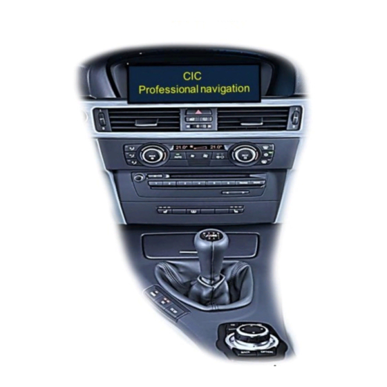
Compatible with BMW vehicles with
Business/Professional CIC-E and CIC-F series
navigation systems or radios with colour display
and 4pin HSD LVDS monitor plug
Product Features
Video-Inserter for factory-infotainment systems
1 Rear-view camera CVBS Input
2 CVBS Video Inputs for After-Market Devices (e.g. DVD-Player, DVD-Tuner)
Automatic Switching to rear view camera input by engagement of reverse gear
Activatable parking guide lines for rear-view camera (not available for all vehicles)
Video-in-motion (ONLY for connected video-sources)
Video-inputs NTSC / Pal compatible
Version 09.02.2023
Video-inserter
RL3-CIC
Video-inserter for rear-view camera
and 2 additional video sources
HW CAM(V100)/(V20)
RL3-CIC
Advertisement
Table of Contents

Related Manuals for NavLinkz RL3-CIC


Summary of Contents for NavLinkz RL3-CIC
- Page 1 Video-inserter RL3-CIC Compatible with BMW vehicles with Business/Professional CIC-E and CIC-F series navigation systems or radios with colour display and 4pin HSD LVDS monitor plug Video-inserter for rear-view camera and 2 additional video sources Product Features Video-Inserter for factory-infotainment systems ...
-
Page 2: Table Of Contents
Case 2: Video interface does not receive the reverse gear signal 2.6. Connection video-interface - external keypad 2.7. Picture settings and guide lines 3. Interface operation 3.1. By I-Drive buttons 3.2. By external keypad 4. Specifications 5. FAQ – Trouble shooting 6. Technical support Version 09.02.2023 HW CAM(V100)/(V20) RL3-CIC... -
Page 3: Prior To Installation
Read the manual prior to installation. Technical knowledge is necessary for installation. The place of installation must be free of moisture and away from heat sources. 1.1. Delivery contents Take down the serial number of the interface and store this manual for support purposes: ____________________ Version 09.02.2023 HW CAM(V100)/(V20) RL3-CIC... -
Page 4: Checking The Compatibility Of Vehicle And Accessories
To delay the switch- back time, additional electronics is required. Guidelines If the video interface does not receive the required information from the vehicle CAN-bus, guide-lines will not be supported. Video input signal NTSC video sources compatible only. Version 09.02.2023 HW CAM(V100)/(V20) RL3-CIC... -
Page 5: Connectors - Video-Interface
*If the PDC graphic is not shown laterally on some vehicles, but only offset in the middle of the display, this cannot be adjusted. If necessary, deactivate the PDC function via Dip-7. See the following chapters for detailed information. After each Dip-switch-change a power-reset of the Interface-box has to be performed! Version 09.02.2023 HW CAM(V100)/(V20) RL3-CIC... -
Page 6: Enabling The Interface's Video Inputs (Dip 2-3)
After each Dip-switch-change a power-reset of the Interface-box has to be performed! 1.5. Settings of the 4 Dip switches (CAN functions – red) Dip position down is ON and position up is OFF. Vehicle/Navigation Dip 1 Dip 2 Dip 3 Dip 4 All vehicles Version 09.02.2023 HW CAM(V100)/(V20) RL3-CIC... -
Page 7: Installation
Before the final installation, we recommend a test-run of the interface. Due to changes in the production of the vehicle manufacturer, there’s always the possibility of incompatibility. 2.1. Place of installation The interface is installed on the factory monitor’s backside. Version 09.02.2023 HW CAM(V100)/(V20) RL3-CIC... -
Page 8: Connection Schema
2.2. Connection Scheme Version 09.02.2023 HW CAM(V100)/(V20) RL3-CIC... -
Page 9: Connections - Factory Monitor
Connect the picture signal cable’s female 4pin connector to the male 4pin HSD connector of the head-unit. Note: If the originalHSD picture signal cable of the vehicle harness is too short for the installation, an HSD extension can be ordered separately with item number CAB-HSD-MF100. Version 09.02.2023 HW CAM(V100)/(V20) RL3-CIC... -
Page 10: 8Pin Pnp Cable
Manual ACC of the 12pin interface cable both have to be connected additionately to S-contact terminal 86s +12V e.g. glove compartment illumination (refer to “Analogue power supply fot the video interface). Version 09.02.2023 HW CAM(V100)/(V20) RL3-CIC... -
Page 11: Analog Power Supply For The Video Interface
12pin interface cable both have to be connected additionately to S-contact terminal 86s +12V (e.g. glove compartment illumination). Connect the female 12pin connector of the 12pin interface cable to the male 12pin connector of the video-interface. Version 09.02.2023 HW CAM(V100)/(V20) RL3-CIC... -
Page 12: Connection - Video Sources
Connect the video RCA of the AV source 1 and 2 to the female RCA connector “Video IN1” ”Video IN 2” of the 12pin interface cable. Connect the video RCA of the rear-view camera to the female RCA connector “Camera IN” the 20pin interface cable. Version 09.02.2023 HW CAM(V100)/(V20) RL3-CIC... -
Page 13: Audio Insertion
6pin to 12pin cable should carry +12V while the reverse gear is engaged. Note: Do not forget to set video interface’s dip5 to ON before testing. Version 09.02.2023 HW CAM(V100)/(V20) RL3-CIC... -
Page 14: Case 1: Video-Interface Receives The Reverse Gear Signal
“Camera IN” while the reverse gear is engaged. Additionally, the +12V (max. 3A) power supply for the rear-view camera can be taken from the green wire of the 12pin interface cable. Version 09.02.2023 HW CAM(V100)/(V20) RL3-CIC... - Page 15 Connect the output connector (87) of the relay to the rear-view camera’s power- cable, like you did it to the green “Reverse-IN” cable before. Connect stabile and permanent +12V to the relay’s input connector (30). Version 09.02.2023 HW CAM(V100)/(V20) RL3-CIC...
-
Page 16: Connection Video-Interface - External Keypad
Connect the female 4pin connector of the keypad to the male 4pin connector of the 12pin interface cable. Note: Even if switching through several video sources by the keypad mightn’t be required, The invisible connection and availability is strongly recommended. Version 09.02.2023 HW CAM(V100)/(V20) RL3-CIC... -
Page 17: Picture Settings And Guide Lines
H-SIZE (horizontal) picture adjustment V-SIZE (vertical) for rear-view camera Note: If the vehicle’s CAN communication does not support the video interface, the guide- lines cannot be used, even if they’re once shown with the first operation! Version 09.02.2023 HW CAM(V100)/(V20) RL3-CIC... -
Page 18: Interface Operation
7V - 25V Stand-by power drain 12mA Stromaufnahme 200mA Video input 0.7V - 1V Video input formats NTSC Temperature range -40°C to +85°C Dimensions video-box 118 x 25 x 112 mm (W x H x D) Version 09.02.2023 HW CAM(V100)/(V20) RL3-CIC... -
Page 19: Faq - Trouble Shooting
Camera input picture fluorescent light which shines Test camera under natural light outside the garage. flickers. directly into the camera. Camera input picture is Protection sticker not Remove protection sticker from lens. bluish. removed from camera lens. Version 09.02.2023 HW CAM(V100)/(V20) RL3-CIC... -
Page 20: Technical Support
6pin to 8pin cable and isolate both ends. Technical Support Please note that direct technical support is only available for products purchased directly from NavLinkz GmbH. For products bought from other sources, contact your vendor for technical support. NavLinkz GmbH...
Need help?
Do you have a question about the RL3-CIC and is the answer not in the manual?
Questions and answers