Sign In
Upload
Download
Table of Contents
Contents
Add to my manuals
Delete from my manuals
Share
URL of this page:
HTML Link:
Bookmark this page
Add
Manual will be automatically added to "My Manuals"
Print this page
×
Bookmark added
×
Added to my manuals
Manuals
Brands
PDK Manuals
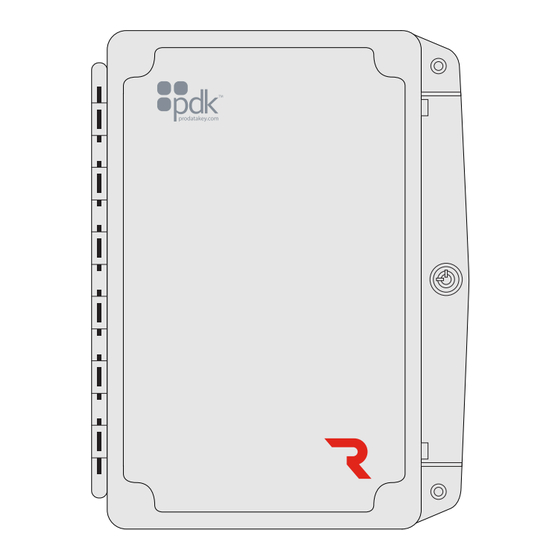
Controller
Red Gate
Quick start manual
PDK Red Gate Quick Start Manual
Wimac controller
Hide thumbs
1
2
3
4
5
6
7
8
9
10
11
Table Of Contents
12
page
of
12
Go
/
12
Contents
Table of Contents
Bookmarks
Advertisement
Table of Contents
1
Package Contents
2
Mounting Controller
3
Reader Connection
4
Communication Connections
5
Power Connection
6
Reference Guide
Download this manual
Quick Start Guide
View the user manual here:
prodatakey.zendesk.com
PN : RGW
www.prodatakey.com
801.317.8802
Copyright © 2022 ProdataKey Inc. All rights reserved. Pdk, Pdk io, and
the Red logos are trademarkes of ProdataKey Inc.
REV 12162022
Table of
Contents
Previous
Page
Next
Page
1
2
3
4
5
Advertisement
Table of Contents
Need help?
Do you have a question about the Red Gate and is the answer not in the manual?
Ask a question
Questions and answers
Related Manuals for PDK Red Gate
Controller PDK Red 4 Quick Start Manual
Door controller (2 pages)
Controller PDK Red 2 Quick Start Manual
(2 pages)
Controller PDK Red 2 Quick Start Manual
Two door controller (2 pages)
Controller PDK RED 2 Quick Start Manual
(2 pages)
Controller PDK Red gate RGE Quick Start Manual
(2 pages)
Controller PDK Red 8 Quick Start Manual
(2 pages)
Controller PDK Red 1 Quick Start Manual
(2 pages)
Controller PDK Red 1 Quick Start Manual
(12 pages)
Controller PDK Red Pedestal RPE Quick Start Manual
Outdoor ethernet controller (2 pages)
Controller PDK Red RGE Quick Start Manual
Ethernet gate outdoor controller (2 pages)
Controller PDK Red 1E Quick Start Manual
(11 pages)
Controller PDK RGW Quick Start Manual
Wimac controller (12 pages)
Controller PDK Red Aux 8 Quick Start Manual
Aux eight controller (10 pages)
This manual is also suitable for:
Rgw
Table of Contents
Print
Rename the bookmark
Delete bookmark?
Delete from my manuals?
Login
Sign In
OR
Sign in with Facebook
Sign in with Google
Upload manual
Upload from disk
Upload from URL


Need help?
Do you have a question about the Red Gate and is the answer not in the manual?
Questions and answers