Advertisement
Quick Links
1. Package Contents
Can Lock (1)
Red Two
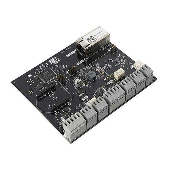
Door Controller (1)
Battery Leads (1)
Enclosure Screws (2)
Diodes (2)
4. Input A / DPS Connection
PORT1
PORT2
+
-
BUS
+
-
BUS
+ -
-
+ -
-
0 1 L
A
B
NC
C
NO
0 1 L
A
B
NC
C
NO
DPS Contact
Double
A
DPS Contact
A
DPS (Door Position Sensor)
- The DPS is mounted on the door frame with a
22/2 wire running from the DPS to the controller. Wire the DPS to the
controller
as shown above. For reporting double doors, wire the two-door
position in series and connect to the controller.
B
AUX Input
- A software rule can be programmed to trigger events or
outputs based on input triggers.
Jumpers (4)
Transformer (1)
14 VDC, 2 Amp
BATTERY
PORT1
12VDC
+ GND
+
-
BUS
B
REX
-
A
B
A
Maglock
- When installing a Maglock, it is typical to install a REX (request to
exit) at the door for free egress. Run an 18/2 wire from the maglock to the
controller
B
REX (Request to Exit)
18/5 wire. Wire the REX to the controller and maglock, as shown above. If
reporting is not needed in the system, simply eliminate the green input wire.
C
Jumper Block
If the jumper is off, the relay is a standard dry contact requiring an input into
C on the relay.
D
AUX Input
based on input triggers.
2. Mounting Controller
POWER
HEART
LINK
ETHERNET
ACTIVITY
POE OUT
POE IN
PORT1
PORT2
-
+
BUS
+
BUS
-
BATTERY
Mounting
-
Mount the enclosure securely to a wall.
5. Input B / REX Connection
PORT1
C
PORT2
-
+
BUS
-
+
BUS
+ -
-
+ -
-
12VDC
0 1 L
A
B
NC
C
NO
0 1 L
A
B
NC
C
NO
+ GND
D
A
Maglock
If using a powered REX,
run to any 12VDC
output on controller.
and REX as shown.
- The REX is mounted at your desired location with an
- Use to designated (+) or (-) board voltage out of NO and NC.
- A software rule can be programmed to trigger events or outputs
3. Reader Connection
A
Reader
+ -
C
A
Reader
- The reader is mounted at the door with a 22/5 or 22/6 wire running
to the door controller. Wire the reader to the controller as shown above. Be
sure to check polarity and voltage prior to powering the controller.
B
OSDP
- Place jumper(s) to enable OSDP (see reference guide for more
information about OSDP.)
- Can be connected to available relay and configured with software
C
Piezo
6. Locking Relay
BATTERY
A
A
Diode
- The provided diode must be installed when using a strike. Install at
the strike with the gray stripe on positive and black on negative.
B
- Used for maglocks (or strikes in fail-safe configuration). Connect the
NC
negative (-) of the maglock or strike to NC on the controller.
- Used for strikes in fail-secure configuration. Connect the negative (-) of
C
NO
the strike to NO on the controller.
D
Jumper Block
- Use to designate (+) or (-) board voltage out of NO and NC. If
the jumper is off, the relay is a standard dry contact requiring an input into C
on the relay.
Red 2 Controller
PORT1
PORT2
+
-
BUS
+
-
BATTERY
BUS
B
+ -
0 1 L
-
0 1 L
-
12VDC
A
B
NC
C
NO
A
B
NC
C
NO
+ GND
B
OSDP
Wiring
C
B
OR
PORT1
D
-
+
BUS
Advertisement

Summary of Contents for PDK Red 2
- Page 1 1. Package Contents 2. Mounting Controller 3. Reader Connection Red 2 Controller PORT1 PORT2 Reader BATTERY Can Lock (1) POWER HEART LINK 0 1 L 0 1 L 12VDC ETHERNET + GND Jumpers (4) ACTIVITY POE OUT POE IN Red Two...
- Page 2 Note - Wiegand readers will not work when OSDP jumpers are installed. Email: support@prodatakey.com Knowledge Base: prodatakey.zendesk.com www.prodatakey.com 801.317.8802 Copyright © 2022 ProdataKey Inc. All rights reserved. Pdk, Pdk io, and the Red logos are trademarks of ProdataKey Inc. REV 06132022...


Need help?
Do you have a question about the Red 2 and is the answer not in the manual?
Questions and answers