Advertisement
Quick Links
1. Package Contents
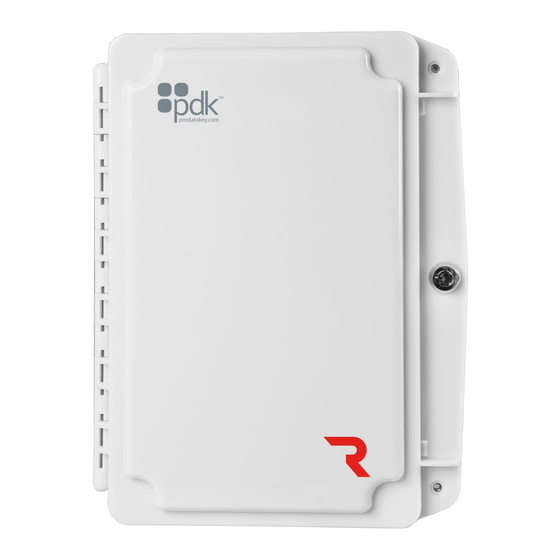
Red Gate Controller (1)
Jumpers (4)
Diodes (2)
4. Input A / DPS Connection
PORT1
PORT2
-
+
BUS
-
+
BUS
+ -
+ -
-
-
0 1 L
A
B
NC
C
NO
0 1 L
A
B
NC
C
NO
DPS Contact
Double
A
DPS Contact
A
DPS (Door Position Sensor)
- The DPS is mounted on the door frame with a
22/2 wire running from the DPS to the controller. Wire the DPS to the
controller
as shown above. For reporting double doors, wire the two door
position in series and connect to the controller.
B
AUX Input
- A software rule can be programmed to trigger events or
outputs based on input triggers.
Battery Leads (1)
Enclosure Screws (4)
Mount
BATTERY
PORT1
12VDC
-
+
+ GND
BUS
B
REX
-
A
B
A
Maglock
- When installing a Maglock, it is typical to install a REX (request to
exit) at the door for free egress. Run an 18/2 wire from the maglock to the
controller
B
REX (Request to Exit)
18/5 wire. Wire the REX to the controller and maglock as shown above. If
reporting is not needed in the system, simply eliminate the green input wire.
C
Jumper Block
If the jumper is off, the relay is a standard dry contact requiring an input into
C on the relay.
D
AUX Input
based on input triggers.
2. Mounting Controller
POWER
HEART
LINK
ETHERNET
POE OUT
ACTIVITY
POE IN
PORT1
PORT2
+
-
BUS
+
-
BATTERY
BUS
+ -
-
+ -
-
0 1 L
A
B
NC
C
NO
0 1 L
A
B
NC
C
NO
12VDC
+ GND
-
Mount the Red Gate enclosure securely to a wall.
5. Input B / REX Connection
PORT1
C
PORT2
+
-
BUS
+
-
BUS
+ -
-
+ -
-
0 1 L
0 1 L
12VDC
A
B
NC
C
NO
A
B
NC
C
NO
+ GND
D
A
Maglock
If using a powered REX,
run to any 12VDC
output on controller.
and REX as shown.
- The REX is mounted at your desired location with an
- Use to designated (+) or (-) board voltage out of NO and NC.
- A software rule can be programmed to trigger events or outputs
3. Reader Connection
A
Reader
+ -
C
A
Reader
- The reader is mounted at the door with a 22/5 or 22/6 wire running
to the door controller. Wire the reader to the controller as shown above. Be
sure to check polarity and voltage prior to powering the controller.
B
OSDP
- Place jumper(s) to enable OSDP (see reference guide for more
information about OSDP.)
C
Piezo
- Can be connected to available relay and configured with software
6. Locking Relay
BATTERY
A
Wiring from Gate Operator
B
NO
COM
NO
A
Gate Operator
- Follow the gate operator wiring instructions to connect the
gate operator to an ELK 912B Isolation Relay.
B
Isolation Relay
- Installation of an ELK 912B isolation relay is recommended
to prevent electrical damage to the Red Gate, The isolation relay is
sold separately.
C
Locking Relay
- Connect the ELK 912B isolation relay to the controller by
connecting the positive wire into a positive port and the negative wire into
the NO port on the board.
D
Jumper Block
- Use to designated (+) or (-) board volatage out of NO and NC.
If the jumper is off, the relay is a standard dry contact requiring an input into
C on the relay negative (-) and center pins.
Red Gate Controller
PORT1
PORT2
-
+
BUS
-
+
BUS
BATTERY
B
-
+ -
-
0 1 L
0 1 L
12VDC
A
B
NC
C
NO
A
B
NC
C
NO
+ GND
B
OSDP
Wiring
PORT1
D
PORT2
-
+
BUS
-
+
BUS
BATTERY
+ -
+ -
-
-
0 1 L
A
B
NC
C
NO
0 1 L
A
B
NC
C
NO
12VDC
+ GND
C
ELK 912B
D2
Isolation Relay
(sold separately)
PORT1
-
+
-
+
BUS
Advertisement

Summary of Contents for PDK Red RGE
- Page 1 2. Mounting Controller 1. Package Contents 3. Reader Connection Red Gate Controller PORT1 PORT2 Reader BATTERY POWER HEART Battery Leads (1) LINK ETHERNET POE OUT ACTIVITY 0 1 L 0 1 L 12VDC POE IN + GND PORT1 PORT2 BATTERY Red Gate Controller (1) 0 1 L 0 1 L...
- Page 2 NOTE - Wiegand readers will not work when OSDP jumpers are installed. PDK Knowledge Base: www.prodatakey.zendesk.com www.prodatakey.com 801.317.8802 Copyright © 2022 ProdataKey Inc. All rights reserved. Pdk, Pdk io, and the Red logos are trademarkes of ProdataKey Inc. REV 06032022...


Need help?
Do you have a question about the Red RGE and is the answer not in the manual?
Questions and answers