
Related Manuals for twin busch TW 260 B4.5


Summary of Contents for twin busch TW 260 B4.5
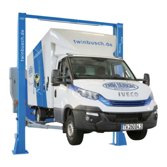
- Page 1 Manual 2-post lift TW260B4.5 TW260B4.5_2-Post-Lifts_Manual_uk_01_20240412.pdf Version -01, 12.04.2024...
-
Page 2: Table Of Contents
Manual 2-post lift TW260B4.5 Table of contents General information ..........................1 Identification of the instructions for use ....................1 Technical data ............................1 Modification of the product ......................... 2 Safety-related information ........................2 5.1. Safety instructions............................ 2 5.2. Warnings and symbols ..........................3 5.1. - Page 3 Manual 2-post lift TW260B4.5 13.3. Hydraulic system ............................ 26 13.4. Circuit diagrams ............................. 27 13.5. Detailed drawing and parts description of the lift ................. 31 13.6. Spare parts list ............................37 Further attachment: ⋅ EU Declaration of Conformity TW260B4.5_2-Post-Lifts_Manual_uk_01_20240412.pdf Version -01, 12.04.2024...
- Page 4 Manual 2-post lift TW260B4.5 Important information: ASSEMBLY You can find the assembly video for this lift on YouTube: https://www.youtube.com/watch?v=otZHoSjtiiQ or scan the QR code. PRODUCT PRESENTATION You can find the product presentation video for this lift on YouTube: https://www.youtube.com/watch?v=hRZ8k7vEkok or scan the QR code. TW260B4.5_2-Post-Lifts_Manual_uk_01_20240412.pdf Version -01, 12.04.2024...
- Page 5 The 24/7 Self-Service Centre is a versatile tool that helps you learn how to maintain and repair your Twin Busch lift, tyre changer or balancer yourself. To open the page on your mobile device, please visit twinbusch.com/qr...
-
Page 6: General Information
We recommend the following extras for this lifting platform, such as special adapters in our shop. https://www.twinbusch.co.uk/2-post-lifts/2-post-lift-6-0-t-clear-floor-HEAVY- LINE::267.html#horizontalTab6 Identification of the instructions for use Instruction manual TW 260 B4.5 of the Twin Busch GmbH, Twin Busch UK Ltd. Ampérestraße 1, 9, Linnell Way... -
Page 7: Modification Of The Product
The manufacturer accepts no liability for improper installation, operation or overloading. Improper use also invalidates the CE certification and the validity of the certificate. If you wish to make any changes, please contact your dealer or the expert staff at Twin Busch GmbH beforehand. Safety-related information Read the operating instructions carefully before operating the lift. -
Page 8: Warnings And Symbols
Manual 2-post lift TW260B4.5 5.2. Warnings and symbols All warnings are clearly visible on the lift to ensure that the user operates the device in a safe and appropriate manner. The warning signs must be kept clean and replaced if they are damaged or missing. Read instructions and safety instructions carefully before use! Read Instructions The lift may only be... -
Page 9: Safety Equipment
Conformity with the product The TW 260 B4.5 2-post lift is CE-certified and complies with the Machinery Directive 2006/42/EC and fulfils the standards EN 1493:2022, EN 60204-1:2018+A1:2009 and EN ISO 12100:2010. See also the EU Declaration of Conformity at the end of the instructions for use. -
Page 10: Technical Specification
Manual 2-post lift TW260B4.5 Technical specification 7.1. Machine description Assembly of the lifting platform 8.1. Before installation 8.1.1. Tools and equipment required ⋅ Suitable lifting tool for bulky and heavy components ⋅ Hammer, pliers ⋅ Phillips and slotted screwdriver ⋅ Set of Allen keys ⋅... -
Page 11: Concrete Conditions
Manual 2-post lift TW260B4.5 8.2. Concrete conditions The lifting platform must be installed on a solid foundation with a compressive strength of more than 3 kg/mm², a flatness of less than 5 mm and a minimum thickness of 250 mm. Detailed information can also be found in the corresponding foundation plan on our homepage at www.twinbusch.co.uk Note: If a new concrete floor is to be poured, it must cure for at least 28 days before a lifting platform can be... - Page 12 Manual 2-post lift TW260B4.5 5) Pre-assembly of the crossbar and limit switch M14 hexagon nut M14 spring washer M14 washer M6 safety nut M6x35 hexagon head screw M14x25 hexagon head screw Roof protection Figure: Pre-assembly of the crossbar 6) Set up both columns. Align the main and secondary pillars with each other (outer edge of base plate to outer edge of base plate approx.
- Page 13 Manual 2-post lift TW260B4.5 8) Fit the crossbar M12x30 hexagon head screw M12 spring washer M12 washer Crossbar Roof protection Figure: Mounting the crossbar 9) Fit the safety catches, the four electromagnets and the corresponding protectors. Safety catch Electromagnet on the Protectors outer surface of the column...
- Page 14 Manual 2-post lift TW260B4.5 Line 2 Line 3 Control unit Line 4 Plug connector Line 1 (under drive-over plate Figure: Electromagnet release connections 10) Install the hydraulic system a) Fit the motor unit M10 nut M10 spring washer M10 washer M10 spring washer M10x35 hexagon head Figure: Mounting the motor unit b) Make sure that all hose ends are clean and free of dirt.
- Page 15 Manual 2-post lift TW260B4.5 Figure: Connecting the hydraulic lines 11) After installing the safety catches, connect the carraiges to the steel cable Align the carraiges on both sides of the column approx. 800 mm above floor level. Ensure that the safety catches on both sides of the column are engaged before you start installing the steel cables.
- Page 16 Manual 2-post lift TW260B4.5 Thread for regulating the cable tension Figure: Fastening the steel cables Caution: After adjusting the steel cable tension, the adjusting nuts on both sides of the column must be locked with another nut! The cables must also be lubricated with WD40 after installation. 12) Install the control unit or control box a) Mount the control unit on the main column.
- Page 17 Manual 2-post lift TW260B4.5 Figure: Connecting the power supply to the control unit c) Fit the limit switch at the top of the main column as shown in the following illustration. Limit switch M4x12 Phillips head screw M4x25 Phillips head screw Connection to the control unit Screw Limit switch...
- Page 18 Manual 2-post lift TW260B4.5 13) Fit the protective covers for the hydraulic lines Protective cover Figure: Fitting the protective covers 14) Fit the support arms a) Insert the support arms into the lifting carriages, paying attention to the interlocking of the anti- rotation blocks.
-
Page 19: Checkpoints According To The Structure
Manual 2-post lift TW260B4.5 17) Fit the chain and door stop protection Chain guard Door stop protection Figure: Fitting the chain and door stop guard 8.4. Checkpoints according to the structure Check Are the columns vertical to the floor? (90°) Are the two columns parallel to each other? Is the oil hose connected correctly? Is the steel cable correctly and firmly connected? -
Page 20: Commissioning
Manual 2-post lift TW260B4.5 Commissioning 9.1. Safety precautions a) If the safety devices are defective or show abnormalities, the lift must not be put into operation under any circumstances! b) Check that all connections of the hydraulic lines are tight and functional. If there are no leaks, the lifting process can be started. -
Page 21: Lifting And Lowering Process Flow Chart
Manual 2-post lift TW260B4.5 9.3. Lifting and lowering process flow chart Lifting process Lowering process Start Start Switch on the power Switch on the power Press the UP button (push-button) Press the DOWN Press the DOWN button and QUICK Down (push-button) Motor drives the gear pump buttons... -
Page 22: Operating Instructions
Manual 2-post lift TW260B4.5 9.4. Operating instructions 9.4.1. Lifting process 1. Read and understand the operating instructions before starting work. 2. Connect the power supply and switch the main switch to ON. 3. Park the vehicle with its centre of gravity in the middle between the two pillars. 4. - Page 23 Manual 2-post lift TW260B4.5 b) Actuate the manual drain (bayonet catch). (Push in the knurled screw and turn -> anti-clockwise: "Open", -> clockwise: "Close") Electromagnetic drain valve Figure: Drain valve With the lifting carriage engaged a) Unscrew the sealing plug to be able to connect the manual hydraulic pump. Motor Hydraulic connection...
-
Page 24: Troubleshooting
Troubleshooting Please note: Do not hesitate to contact the expert staff at Twin Busch GmbH if you are unable to rectify a fault yourself. We will be happy to help you solve the problem. In this case, please document the fault and send us pictures and a precise description of the fault so that we can identify and rectify the cause as quickly as possible. -
Page 25: Maintenance
Manual 2-post lift TW260B4.5 Maintenance Regular maintenance of your lift will ensure a long and safe service life. Suggestions for maintenance intervals and the activities to be carried out are listed below. How often you service your lift depends on the ambient conditions, the degree of soiling and, of course, the stress and load on the lift. -
Page 26: Behaviour In The Event Of A Malfunction
If the lift malfunctions, simple faults may be the cause. Use the following list for troubleshooting *). If the cause of the fault is not listed or cannot be found, please contact the expert Twin Busch GmbH team. Never attempt to carry out repairs yourself, especially on safety equipment or electrical system components. -
Page 27: Appendix
Manual 2-post lift TW260B4.5 Appendix 13.1. Dimensions of the lift Page |22 Misprints, errors and changes excepted. -
Page 28: Foundation Requirement And Working Area
Manual 2-post lift TW260B4.5 13.2. Foundation requirement and working area Requirements for the concrete: Concrete C20/25 according to DIN 1045-2 (previous designation: DIN 1045 concrete B25). Floor must be level and have a flatness of less than 5 mm/m. Newly poured concrete must cure for at least 28 days. Foundation dimensions: Ideally, the entire hall floor should be made of C20/25 concrete with a thickness of at least 250 mm... - Page 29 Manual 2-post lift TW260B4.5 Other requirements: The surrounding soil must be suitable for the load, e.g. no sandy soils, etc. Reinforcements in the concrete are not mandatory for proper use of the lift, but are recommended. If in doubt, the foundation should be determined and checked by a structural engineer. The following must be observed for soil exposed to frost: In the case of frost exposure, the concrete must correspond to exposure class XF4, as dripping de-icing agent cannot be ruled out.
- Page 30 Manual 2-post lift TW260B4.5 Drill Clean Hammer in Fasten Page |25 Misprints, errors and changes excepted.
- Page 31 Manual 2-post lift TW260B4.5 13.3. Hydraulic system 1. Master cylinder 2. Secondary cylinder 3. Electromagnetic drain valve 4. Throttle valve 5. Motor 6. Clutch 7. Gear pump 8. Non-return valve (one-way valve) 9. Pressure relief valve (max.: 19.4 Mpa) 10. Throttle check valve 11.
- Page 32 Manual 2-post lift TW260B4.5 13.4. Circuit diagrams Page |27 Misprints, errors and changes excepted.
- Page 33 Manual 2-post lift TW260B4.5 Page |28 Misprints, errors and changes excepted.
- Page 34 Manual 2-post lift TW260B4.5 Page |29 Misprints, errors and changes excepted.
- Page 35 Manual 2-post lift TW260B4.5 Page |30 Misprints, errors and changes excepted.
- Page 36 Manual 2-post lift TW260B4.5 13.5. Detailed drawing and parts description of the lift Name Drawing no. Quantity Feature Steel cable L=12.490mm 8226E-A8 Assembly M20 hexagon nut GB/T6170-2000 standard M16*220 anchor bolt standard Page |31 Misprints, errors and changes excepted.
- Page 37 Manual 2-post lift TW260B4.5 Name Drawing no. Quantity Feature Oil line L=10100 Motor/hydraulic unit Assembly Oil line L=2265 / connector L=70 Assembly Hydraulic cylinder 8225E-A4-B2 Assembly Sprocket mount 8226E-A4-B2 Welded Type B Circlip 25 GB/T894.2-1986 standard Bolt 8226E-A4-B4 galvanised Bearing 2548 SF-1 standard Sprocket wheel...
- Page 38 Manual 2-post lift TW260B4.5 Name Drawing no. Quantity Property Stop block (safety catch) 8224E-A1-B3 galvanised Safety catch 8224E-A1-B2 galvanised M6*16 (cross recess) GB/T818-2000 standard M6*10 (cross recess) GB/T818-2000 standard Electromagnet MQZ2-10 8224E-A1-B4 Assembly Ø20 Cable entry ring 8224E-A1-B6 Rubber Electromagnet cover 8224E-A1-B5 Plastic Page |33...
- Page 39 Manual 2-post lift TW260B4.5 Name Drawing no. Quantity Feature Locking pin Ø2.5*30 GB/T91-2000 standard Washer galvanised Bearing 2518 SF-1 standard Idler pulley (bottom) 8225E-A1-B2 galvanised Glider 8224-A3-B6 Nylon Anti-rotation bolt 8225E-A3-B4 galvanised Pressure spring 8224-A3-B5 galvanised Tooth block 8225E-A3-B4 galvanised Parallel key pin 5*35 GB/T879.1-2000 standard...
- Page 40 Manual 2-post lift TW260B4.5 Name Drawing no. Quantity Feature M6 washer (flat) GB/T95-1985 standard Threaded hook 8224-A13 standard Chain guard 2700*180 Fabric M8*12 countersunk head screw (cross GB/T819.1-2000 standard recess) M8*20 countersunk head screw (hexagon GB/T70.3-2000 standard socket) Rubber shim 8225E-A7-B4-C4 Rubber Turntable...
- Page 41 Manual 2-post lift TW260B4.5 Name Drawing no. Quantity Feature Drive-over plate 8225E-A9 Q235A Drive-over plate Base plate 8225E-A8 Welded Inner support arm tube 8226E-A5-B3 Welded Centre support arm tube 8226E-A5-B2 Welded Support arm outer tube/support arm 8226E-A5-B1 Welded Circlip 38 GB/T894.2-1986 standard Tooth block (support arm)
- Page 42 Manual 2-post lift TW260B4.5 13.6. Spare parts list Quantit Name Specification Picture Main switch LW26GS-20/04 Push button Y090-11BN Operating light AD17-22G-AC24 JBK-160VA380V-24V Transformer JBK-160VA220V-24V CJX2-1210/AC24 AC contactor DZ47-63 C16/3P Circuit breaker DZ47-63 C32/2P Circuit breaker DZ47-63 C3/1P Limit switch TZ8108 Emergency stop switch Y090-11ZS/RED Bridge rectifier...
- Page 43 Manual 2-post lift TW260B4.5 Quantit Name Specification Picture Relay holder PTF-08A Time relay ST6PA-5S/AC24V Time -Relay holder PYF-08AE Control unit housing 260*460*135 Mechanical spare parts Name Drawing no. Quantity Feature Glider 8224-A3-B6 Nylon 1010 Rubber shim 8225E-A7-B4-C4 Rubber O-ring Inside diameter 23.6*3.55 Y-shaped sealing ring SD70*60*8 Dust protection ring...
- Page 44 Conversions and major repairs Kind Date / Name...
- Page 45 Notes...
- Page 46 Notes...
Need help?
Do you have a question about the TW 260 B4.5 and is the answer not in the manual?
Questions and answers