Table of Contents
Advertisement
Advertisement
Table of Contents

Related Manuals for Ikegami OCP-200


Summary of Contents for Ikegami OCP-200
- Page 1 OCP-200 Operation Control Panel OPERATION MANUAL (Temporary Version for V07)
- Page 2 Copyright © 2007 Ikegami Tsushinki Co., Ltd We reserve the copyright on the software we create. No part of this publication may be modified or reproduced in any form, or by any means, without prior written permission from Ikegami Tsushinki Co., Ltd.
-
Page 3: Table Of Contents
4.5 MAINTE ........................4-14 4.6 USER ........................... 4-16 4.7 WFM/PM ........................4-17 5. CONTROL KNOB OPERATION..............5-1 5.1 Camera Data Control..................... 5-1 5.2 Control logic of OCP-200....................5-3 5.3 Reconnection Process....................5-4 5.4 Knob Free Function ....................... 5-5 OCP-200 0702 VOL7 (E)(U) - Page 4 13.1 When Alarm Lamp is flashing ..................13-1 13.2 OCP Reset Procedure ....................13-2 13.3 Initial Factory Setting ....................13-3 13.4 When “RAM DATA IS BROKEN” is displayed ............13-3 14. SPECIFICATIONS................... 14-1 14.1 Rating/Performance....................14-1 14.2 Pin Assignment for External Connector..............14-2 OCP-200 0702 VOL7 (E)(U)
-
Page 5: Outline
● Knob-free function OCP-200 employs knob-free function which has merits of both absolute control by potentiometer and relative control by Rotary Encoder. It provides two merits of good knob rotation feeling of potentiometer and avoiding data jump of camera caused by Rotary Encoder position at panel control switching. -
Page 6: External Appearance
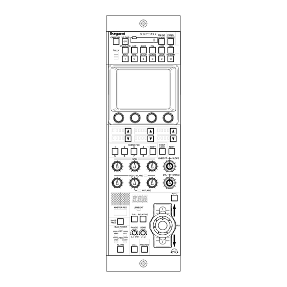
1-2 1. OUTLINE 1.3 External Appearance 1) VR TYPE OCP-200 0702 VOL7 (E)(U) - Page 7 1. OUTLINE 1-3 2) JOYSTICK TYPE OCP-200 0702 VOL7 (E)(U)
-
Page 9: Nomenclature And Functions
Will show each function block, sine OCP has so many control items. VR TYPE 1.Camera Function Portion 2. LCD Menu Portion 3. Select Function Portion 4. Control Knob Portion 5. IRIS/PEDESTAL Control Portion JOYSTICK 7. Status Indicate Portion TYPE 6. IRIS/PEDESTAL Control Portion OCP-200 0702 VOL7 (E)(U) -
Page 10: Camera Function Portion
Push this switch for power supply ON from power supply OFF (Switch lamp: OFF). Keep pushing this switch 2 seconds for power supply OFF from power supply ON (Switch lamp: ON). This switch only enables when OCP-200 is connected to BS/CCU (BS-79LP etc.) which has camera power supply control function. - Page 11 Executes AWB (Auto White Balance) or ABB (Auto Black Balance). After completing execution, lamp turns off when the result is good, but lamp blinks when the result is no good. In case of NG, press this switch to clear lamp blinking. OCP-200 0702 VOL7 (E)(U)
-
Page 12: Lcd Menu Portion
Enables LCD menu to maintenance mode. ・ USER Switch Can be assigned one function by the user. Registration required beforehand and the function can be called quickly. *Not controllable yet. ・ WFM/PM Switch Calls WFM/PM selection switch on LCD display. OCP-200 0702 VOL7 (E)(U) -
Page 13: Select Function Portion
The switch blinks when ▲ or ▼ switch is pushed between a few seconds when there is priority in OCP. The confirmation sounds and can move the option from the OCP side to the camera head by having pushed for about one second after the switch starts blinking. OCP-200 0702 VOL7 (E)(U) -
Page 14: Control Knob Portion
Note Previous OCP has a function of Control Knob uncontrollable until moving to the center after Scene File is loaded. However, OCP-200 doesn’t have this function because control logic of Control Knob is different. Use Knob Free function in order to move Control Knob to the center after Scene File loading(See “5.4 Knob Free... -
Page 15: Iris/Pedestal Control Portion (Vr Type)
By pressing this switch while pressing KNOB FREE Switch, R/G/B PED/FLARE Control Knob can be set Pedestal Control or Flare Control. LED lights when the switch is set to Flare Control. 2.5 IRIS/PEDESTAL Control Portion (VR TYPE) OCP-200 0702 VOL7 (E)(U) - Page 16 Call switch will light when call switch of camera head and BS/CCU is pressed. IRIS Control (VR TYPE) ⑨ To control IRIS. At the AUTO IRIS mode, IRIS can be controlled with +/- 1 stop of F number. (See separate volume of “Iris Control Procedure” for the detail) OCP-200 0702 VOL7 (E)(U)
-
Page 17: Iris/Pedestal Control Portion (Joystick Type)
FULL/RELATIVE Switch (JOYSTICK TYPE) ④ ・ FULL Switch To fix Iris Control range of ⑧ to FULL Range. ・ RELATIVE Switch To set IRIS CONTROL to Relative Mode. (See separate volume of “Iris Control Procedure” for detail operation.) OCP-200 0702 VOL7 (E)(U) - Page 18 To control IRIS and Master PEDESTAL by joystick. At the AUTO IRIS mode, IRIS can be controlled with +/- 1 stop of F number. Press joystick head to PREVIEW switch “ON”. Control action is parallel operation with PREVIEW Switch. (See separate volume of “Iris Control Procedure” for the detail) OCP-200 0702 VOL7 (E)(U)
-
Page 19: Status Indicate Portion (Joystick Type)
OCP setting. To correct shifted VR position data, set Knobs on the mechanical center first and press STANDARD switch mentioned at “2.1 Camera Function Portion” with pushing KNOB FREE switch. This procedure sets mechanical center to previous control center of all Knobs. OCP-200 0702 VOL7 (E)(U) - Page 20 OPEN : Disconnection or breaking cable SHORT : Short circuited ALARM Indicator ⑦ Alarm lamp will blink when any NG is found on the system by the detection of self-diagnosis function. OCP-200 0702 VOL7 (E)(U)
-
Page 21: Connector Panel
And it has Tally In/Out and Program Camera Number Output capability. (See “14.2 Pin Assignment for External Connector” for the detail of Pin Assignment) NET/ICCP Changeover Switch ⑤ To change between Network connection and Ikegami Command (ICCP) connection. : For Network connection ICCP : For Ikegami Command connection... -
Page 23: Network Operation
3. NETWORK OPERATION 3-1 3. NETWORK OPERATION OCP-200 features Network Operation. Concept and Setup Procedure for Network Operation. are described in this summary 3.1 Concept image of Network CAMERA HEAD BS/CCU Existing Ikegami Control Command <=> Ikegami Network Command BSH-200... -
Page 24: Typical System Configuration
3-2 3. NETWORK OPERATION 3.2 Typical System Configuration 1) Case for 1 Studio and 2 Control Rooms Studio Rack Room BSH-200 Operation Room-1 Operation Room-2 CPH-200 CPH-200 OCP-200 0702 VOL7 (E)(U) - Page 25 3. NETWORK OPERATION 3-3 2) Case for 2 Studios and 2 Control Rooms Studio-1 Studio-2 Rack Rack Room-1 Room-2 BSH-200 BSH-200 Operation Room-1 Operation Room-2 CPH-200 CPH-200 OCP-200 0702 VOL7 (E)(U)
-
Page 26: Network Id Setup
To set ID with rotary switches located on connector panel of bottom side. In case of network connection, set “NET” of slide switch. 2) Other Unit Setup See operation manual such as “CPH-200/BSH-200 Setup Manual) or others OCP-200 0702 VOL7 (E)(U) -
Page 27: Network Connection
See operation manual such as “CPH-200/BSH-200 Setup Manual) or others for the detail of Setup ・Connection between CPH-200 and network capable Control Panel CPH-200 and CPH-200(CPHUB) are connected by Ikegami CP Cable. CP Cable should be connected to CP Connector of CPH-200 and connected to Command Connector of Control Panel. -
Page 29: Lcd Menu Operation
4. LCD MENU OPERATION 4-1 4. LCD MENU OPERATION The OCP-200 provides various functions with LCD touch panel, which enable you to confirm the ON/OFF status of the camera functions as well as adjust each functions on the LCD screen by using the Rotary Encoder Knob. - Page 30 If the parameter was changed when the function was off, there is a possibility to reflect to the video when the function turns on. OCP-200 0702 VOL7 (E)(U)
-
Page 31: Info
Used to select ON/OF Rotary Encoder K F the Auto Knee correction Mode. Black STR/PRS Used to select ON/OFF the Black Stretch/Press function. When ON, the Rotary Encoder Knob #4 is used to select the mode and the selected mode is displayed on the box. OCP-200 0702 VOL7 (E)(U) -
Page 32: Setup
(+100% to -100%) is displayed. Also ON/OFF switch related the adjusting item is displayed on the right of the white bar. To adjust values with Rotary Encoder Knob 1, 2, 3, and 4. OCP-200 0702 VOL7 (E)(U) - Page 33 Black Gamma Adjustment Flare OFF Flare ON/OFF Matrix OFF Matrix ON/OFF BLK Gamma Black Gamma ON/OFF BLK STR/PRS Black Stretch/ Press ON/OFF Step Gamma Step Step Gamma Select *Gray shadowed items are controlled by Rotary Encoder Knob. OCP-200 0702 VOL7 (E)(U)
- Page 34 White Clip ON/OFF Matrix OFF Matrix ON/OFF Knee OFF Knee ON/OFF Auto Knee Auto Knee ON/OFF Others Smooth Knee Smooth Knee Select Super Knee Super Knee Select *Gray shadowed items are controlled by Rotary Encoder Knob. OCP-200 0702 VOL7 (E)(U)
- Page 35 Z. Track Gain Zoom Tracking DTL Adjustment Zebra IND. Zebra Indicator ON/OFF DTL OFF DTL ON/OFF Skin DTL Skin DTL ON/OFF Z.Track Skin Zoom Tracking DTL ON/OFF *Gray shadowed items are controlled by Rotary Encoder Knob. OCP-200 0702 VOL7 (E)(U)
- Page 36 Key INV. Key Invert Zebra IND. Zebra Indicator ON/OFF DTL OFF DTL ON/OFF Color DTL Color DTL ON/OFF HI-Light Gain HI-Light DTL Gain Adjustment Limit HI-Light DTL Limit DTL OFF DTL ON/OFF HI-Light DTL HI-Light DTL ON/OFF OCP-200 0702 VOL7 (E)(U)
- Page 37 Color Phase Adjustment (Fine) Width1 Width 1 Adjustment Width2 Width 2 Adjustment Key INV. Key Invert Zebra IND. Zebra Indicator ON/OFF CSTM Color 1 Custom Color 1 ON/OFF *Gray shadowed items are controlled by Rotary Encoder Knob. OCP-200 0702 VOL7 (E)(U)
- Page 38 B / Mg B Hue Blue Hue Adjustment B SAT. Blue Saturation Adjustment Mg Hue Magenta Hue Adjustment Mg SAT. Magenta Saturation Adjustment Color CORR. Color Corrector ON/OFF *Gray shadowed items are controlled by Rotary Encoder Knob. OCP-200 0702 VOL7 (E)(U)
- Page 39 5) MODE SWITCH (CAMERA SETUP) By pressing MODE SWITCH, ON/OFF for Camera Head or the CCU/BS functions of which BS/CCU has control function can be selected. The screen is divided into 4 pages by function or item. OCP-200 0702 VOL7 (E)(U)
- Page 40 Electronic shutter ON/OFF VAR. Variable shutter ON/OFF Black STR/PRS Black Stretch/ Press ON/OFF Super V Super V selection Shutter Electronic shutter speed selection Black STR/PRS Black Stretch/ Press selection *Gray shadowed items are controlled by Rotary Encoder Knob. OCP-200 0702 VOL7 (E)(U)
- Page 41 4. LCD MENU OPERATION 4-13 6) CHARACTER(CAMERA SETUP) By pressing CHARCTER Switch, below four items can be setup; ・Camera Menu ・BARS TITLE ・Camera ID ・Scene File Name See “10. CHARACTER SETUP” for detail. OCP-200 0702 VOL7 (E)(U)
-
Page 42: Mainte
By Rotary Encoder Knob 2, set BS/CCU No. to assign to OCP. To cancel the setting, keep pushing Clear icon 2 seconds. To enter the setting, keep pushing Enter icon 2 seconds. In case of Ikegami command control, only PGM Camera No. can be set. OCP-200 0702 VOL7 (E)(U) - Page 43 Head Bars ON/OFF BS Level Red/Green/Blue BS Level Control Head Bars Head Bars ON/OFF BS BLK Set Red/Green/Blue BS Black Set Control Head Bars Head Bars ON/OFF *Gray shadowed items are controlled by Rotary Encoder Knob OCP-200 0702 VOL7 (E)(U)
-
Page 44: User
Start icon to execution. Set “Diascope” ON/OFF occasionally. If reference setting was incomplete, Start switch will blink for alert. By pressing Start icon to cancel error condition. Or pressing Start icon on execution to stop reference setting procedure. 4.6 USER Not controllable yet. OCP-200 0702 VOL7 (E)(U) -
Page 45: Wfm/Pm
In case of Super/Mix is set to “ON”, selected signal is output for PM and WFM. In case of “OFF”, 1ch signal with later Selection priority basis output to PM and WFM. However, this switch will be active when BS/CCU is connected to OCP. It will be “OFF” at the self-contained operation. OCP-200 0702 VOL7 (E)(U) -
Page 47: Control Knob Operation
Camera Control by mixing them up.) 1) Absolute Control This control logic is used for traditional Ikegami OCP/RCP and the changed parameter with potentiometer is A/D converted and transmitted. Transmitted data(Absolute Value Data) is reflected to Volume File. - Page 48 Connection change because control value Maintenance disconnection doesn’t is not reflected from cause camera data jump. rotation angle. To go back to original value, it Fine adjustment available. is necessary to check actual video indicated answer panel. OCP-200 0702 VOL7 (E)(U)
-
Page 49: Control Logic Of Ocp-200
5. CONTROL KNOB OPERATION 5-3 5.2 Control logic of OCP-200 OCP-200 is the control panel combining the both advantages of volume control of traditional OCP and Rotary Encoder control of MCP. It achieves good control feeling of potentiometer and the function to avoid data jump at the panel connection change. -
Page 50: Reconnection Process
Absolute Control Data when camera and panel is re-connected. In case of OCP-200, data jump will not happen at re-connection by camera power ON/OFF or Panel Enable ON/OFF if Control Knob position is different from before and after reconnection because Control Knob position data reflects Relative Control Data when camera and panel is re-connected. -
Page 51: Knob Free Function
5. CONTROL KNOB OPERATION 5-5 5.4 Knob Free Function OCP-200 has Knob Free Function. This function enables to clear knob offset and to expand control range because knob control is disabled when this switch is pushed. 1) Control Logic At the Knob rotation, potentiometer may reach to MAX or MIN and further control becomes unable. - Page 52 2) Knob Fee Control Item The following items are controllable with Knob Free Function. ・R/G/B GAIN ・R/G/B PED ・MASTER PED ・R/G/B FLARE ・MASTER FLARE ・KNEE POINT/SLOPE ・DTL ・GAMMA ・IRIS(Only available under Relative Control) ・IRIS RANGE/SENSE(Only available under Relative Control) OCP-200 0702 VOL7 (E)(U)
-
Page 53: Manual Set/ Manual Clr
Manual Set keep pressing for a moment to be executed. After execution or pressing the Cancel switch, the screen returns to the previous menu. Note If the control item is set OFF, Manual Set and Manual Clear are disabled. OCP-200 0702 VOL7 (E)(U) -
Page 54: Lumped Manual Clear Of Control Knob Operation
Rotary Encoders are released. Example; When you use the control knob and Rotary Encoder Knob for adjusting the values for the item of R.GAIN, its value is released. If the control item is set OFF, Manual Set and Manual Clear are disabled. OCP-200 0702 VOL7 (E)(U) -
Page 55: All Manual Set / All Manual Clear
6.3 All Manual Set / All Manual Clear Manual Set and Manual Clear are available for all functionality of Camera Head and BS/CCU. 1. Push “MAINTE” Switch on top side of the Panel. 2. Push “FILE OPERATON” on LCD screen. OCP-200 0702 VOL7 (E)(U) - Page 56 This operation executes Manual Set or Manual Clear for all control items, if control item is set OFF. However, some of functionality in Camera Head and BS/CCU doesn’t apply to Manual Set and Manual Clear because of its specification. OCP-200 0702 VOL7 (E)(U)
-
Page 57: Memory Card Operation
And also, by using memory card, firmware version up of OCP-200 is also available. (See “12. FIRMWARE UPDATING” for the detail ) 7.1 Type of Memory Card... -
Page 58: Insert/Extract Of Memory Card
Do not extract Memory Card when access indicator on the slot lights or Saving/Loading data to/from Memory Card. Data or Card itself may be damaged. Annex Pay attention. Removing sensor buzzer will not beep BUZZER, if it is set "OFF". OCP-200 0702 VOL7 (E)(U) -
Page 59: Format And Name Change Of Memory Card
1. Insert Memory Card slowly to the slot with proper position (contacts on behind and notch on left bottom) 2. Push MAINTENANCE Switch in Function Switches on top side of LCD. Push FILE OPERATION Switch on LCD menu. 3. Push MEM.CARD SAVE/LOAD on LCD Menu. OCP-200 0702 VOL7 (E)(U) - Page 60 7. Push Yes switch to start formatting. Buzzer will beep after format completing. Push No switch to cancel formatting. <Change of Card Name> Not available to change only Card Name yet. In case of Card Name change, re-format of SD Card is required. OCP-200 0702 VOL7 (E)(U)
-
Page 61: Memory Card Name / File Name Operation
11 letters for Memory Card naming and 8 letters and 3 letters of extension for File naming are available. Below alphabets, numerals and symbols can be used: Characters: ABCDEFGHIJKLMNOPQRSTUVWXYZ!#$%&'( )+-=@[ ]^_{}0123456789 If no File Name is input, the File Name will be “NONAME01” automatically. OCP-200 0702 VOL7 (E)(U) -
Page 62: File Data Save To Memory Card
4. Input File Name by using switches on LCD and Rotary Encoder Knob. 5. Turn Save switch to "ON". 6. Push Execute switch. Execute switch lights and File Date will be saved, Buzzer will beep at the completing. OCP-200 0702 VOL7 (E)(U) - Page 63 7. MEMORY CARD OPERATION 7-7 Annex If the same file name is existed, below warning message will come up. Push “Yes” to overwrite. Or, push “No” to cancel saving. [ WARNING ] FILE ALREADY EXIST Continue? OCP-200 0702 VOL7 (E)(U)
-
Page 64: File Data Loading From Memory Card
Extension. Annex Push Name of File Data to indicate File Data information and it allows to see Camera Model Name and Type of File. And if CONTROL/SELECT Knob is rotated, following data will be indicated continuously. OCP-200 0702 VOL7 (E)(U) - Page 65 DIFFERENT FILE DATA FILE : LENS FILE Continue? If "YES" is pushed, below warning will come up. It is unable to read out in this case. Push “OK” to cancel. [ ERROR ] ! NO DATA LOAD OCP-200 0702 VOL7 (E)(U)
- Page 66 The File Data saved as ALL DATA can be read out for another file type. (Below example shows that an All DAT is read out for SNAP SHOT data) Push “YES” switch in below window. [ WARNING ] DIFFERENT FILE DATA FILE : ALL DATA Continue? OCP-200 0702 VOL7 (E)(U)
-
Page 67: Delete Of File Data From Memory Card
4. Rotate for File Search Control Knob to choose the needed file. Or, input new File Name buy using LCD switch, Cursor Control Knob and Character Selection Control select Knob. ABCDEFGH.ALL File Search Control 5. Turn FileClear Switch to "ON". OCP-200 0702 VOL7 (E)(U) - Page 68 6. Push Execute switch. ABCDEFGH.ALL CAMERA : HDK-79EX DATA : ALL DATA Continue? 7. Push "YES" to delete File Data. Or, push “NO” to cancel deleting. Annex If type of file data is different, the file will be deleted. OCP-200 0702 VOL7 (E)(U)
-
Page 69: Message Indication
DIFFERENT CAMERA CODE CAMERA : (HDK-79EX) Continue? At the data read out, this message will come up [ WARNING ] when the different type of data is selected. DIFFERENT FILE DATA CAMERA : (LENS DATA) Continue? OCP-200 0702 VOL7 (E)(U) - Page 70 [ ERROR ] is read out. ! FILE NOT FOUND Any system error happens in Memory Card [ ERROR ] system. ! FILE SYSTEM ERROR Type of File Data is different. [ ERROR ] ! DIFFERENT TYPE DATA OCP-200 0702 VOL7 (E)(U)
- Page 71 [ ERROR ] ! FILE BROKEN File data can not be created at the data saving. [ ERROR ] ! FILE CANNOT CREATE File Name of data can not be supported. [ ERROR ] ! FILE NAME ERROR OCP-200 0702 VOL7 (E)(U)
- Page 72 Camera Head Power OFF at Data Save/Load.. [ ERROR ] ! CAMERA HEAD POWER OFF Scene File is ON at Data Save/Load. Turn Scene [ ERROR ] File OFF before Data Save/Load. ! SCENE FILE ON Turn it OFF OCP-200 0702 VOL7 (E)(U)
-
Page 73: Control Depth Setting
8. CONTROL DEPTH SETTING 8-1 8. CONTROL DEPTH SETTING 8.1 Outline Control Depth of OCP-200 can be set for below four levels. Control depth setting is protected by password. ① Basic : like RM-11. Operation Menu in LCD Display is disable. -
Page 74: Changing The Password
At the emergency situation to release control limitation if Password is forgotten or the person in charge is out, the setup can be cleared to back default setting. (See “13.3 Initial Factory Setting” for detail operation procedure.) OCP-200 0702 VOL7 (E)(U) -
Page 75: The Details Of Control Depth
USER FUNCTION ----- STANDARD SET ----- FACTORY STANDARD SET USER WFM / PM ----- MANUAL SET MAN. SET / CLR MANUAL CLEAR ALARM ----- SCENE FILE STORE ----- ※1 Not available to change to MODE SWITCH. OCP-200 0702 VOL7 (E)(U) - Page 76 8-4 8. CONTROL DEPTH SETTING ① Basic Not available to change from INFORMATION to MODE SWITCH *Can not store SCENE FILE. ② Standard Not available to change from INFORMATION MODE SWITCH OCP-200 0702 VOL7 (E)(U)
- Page 77 8. CONTROL DEPTH SETTING 8-5 ③ Extended ④ Complete No restriction. Note Some under-developing functions are included in Complete Control Item. Specification may be changed occasionally. OCP-200 0702 VOL7 (E)(U)
-
Page 79: Standard Function
9.1 Outline “STANDARD” Function will clear current setting of Camera Head and BS/CCU and back to standard setting by Control Panel operation. OCP-200 has two modes of Standard Function. They are “Clear to Standard” and “Recall Preset File”. “Clear to Standard” function sends existing commands for each control item. -
Page 80: Operating Procedure
Below menu page comes up, and either Clear to Standard function or Recall Preset File function can be selectable. 1) Clear to Standard Either Basic mode or Complete mode is selectable in Clear to Standard function. OCP-200 0702 VOL7 (E)(U) - Page 81 File loading(Camera Head or BS/CCU) can be selected and controlled separately. If the Camera Head and/or BS/CCU don’t have Preset File function, Head Switch and/or BS/CCU switch indicate Gray and it shows that it is unable to be selected. OCP-200 0702 VOL7 (E)(U)
- Page 82 “Pop-up Window” for the confirmation. If “No” is pressed, the menu will return to previous page without execution. Recall Preset File HEAD FACTORY DATA Continue? Press ”Yes” to start execution. Please wait!! Now loading... Pop-up window comes up until the execution completed to show processing going on. OCP-200 0702 VOL7 (E)(U)
- Page 83 After Preset File loading, Camera Head and/or BS/CCU may be reset automatically for initialize. In that processing, OCP may be Panel Enable off or LCD screen off, but OCP is NOT in trouble. This is correct reaction because of unlocked command. OCP-200 0702 VOL7 (E)(U)
- Page 85 10. CHARACTER SETUP 10 - 1 10. CHARACTER SETUP Press “SETUP” switch in Function Switches on top side of the panel. By pressing “CHARCTER” Switch, ・Camera Menu ・BARS TITLE ・Camera ID ・Scene File Name …can be setup. OCP-200 0702 VOL7 (E)(U)
-
Page 86: Camera Menu Setup
5. After all the setting is entered, Menu page should be closed. The procedures are; ・Select and enter QUIT on PM screen by Menu control. ・Push Quit switch on LCD ・Push one of Function Switch on the top side of panel. OCP-200 0702 VOL7 (E)(U) -
Page 87: Bars Title Entry
Enter Switch Select Knob 3. Push Enter Switch to indicate ON/OFF selection mode, current setting(ON or OFFF) will blink. 4. Rotate Select Knob to change ON/OFF setting. 5. Press Ener Switch to leave from ON/OFF selection mode. OCP-200 0702 VOL7 (E)(U) - Page 88 Edit mode(Previous BARS TITlE setting remainds).BARS TITLE To clear all BARS TITLE. ・[CLR] : To save entered and edited BARS TITLE, and leae from Edit ・[ENTRY] : mode. BARS TITLE are updated and displayed after the entry. OCP-200 0702 VOL7 (E)(U)
- Page 89 ・Select Knob Horizontal Position control for BARS TITLE. : ・Next Knob Vertical Position control for BARS TITLE. : Leaving from Position Setup Mode ・Enter Knob : 5. Push Enter Switch to leave from Position Setup Mode. OCP-200 0702 VOL7 (E)(U)
-
Page 90: Camera Id Entry
3. After the input, push ”Store” switch to save Camera ID to the memory. 4. When “PM IND/PAGE” switch is pressed, PM screen will change to Camera ID screen and entered Camera ID will be displayed accordingly. OCP-200 0702 VOL7 (E)(U) - Page 91 This function only available with Camera or BS/CCU which has Camera ID function. At the multiple panel operation, if Camera ID and Scene File Name are set at the same time, those setting items may become confused. OCP-200 0702 VOL7 (E)(U)
-
Page 92: Scene File Name Entry
4. INS Switch 5. DEL Switch :To delete a character. 6. Clear Switch :To delete all input characters. 7. Store Switch :To enter Scene File Name to memory in camera side. 8. Quit Switch :To quit entry page. OCP-200 0702 VOL7 (E)(U) - Page 93 At the Scene File Name entering process, Scene File is changed by another panel, entering menu will be cleared automatically. At the multiple panel operation, if Camera ID and Scene File Name are set at the same time, those setting items may become confused. OCP-200 0702 VOL7 (E)(U)
-
Page 95: Panel Set-Up(Panel Config.)
11. PANEL SET-UP(PANEL CONFIG.) 11-1 11.PANEL SET-UP(PANEL CONFIG.) OCP-200 has many functions, however, Control Logic and setup item can be changed in accordance with each system application and control manner. 11.1 Operating Procedure 1. Press “MAINTE” switch in Function Switches on top side of the panel. - Page 96 5. Selecting control item by Rotary Encoder, and press “Edit” switch. The entered setting is not final entry but it still temporary at this stage. If one of setting is changed, “Set all” will blink to indicate the change. OCP-200 0702 VOL7 (E)(U)
- Page 97 If it returns from Panel Config. page without pressing “Set all” switch, temporary set-up data is cleared and it returns to previous set-up. However, only DATE/TIME menu set-up is changed by pressing “Edit” switch, not by pressing “Set all”, because of its characteristics. OCP-200 0702 VOL7 (E)(U)
-
Page 98: Initialize Of Panel Config
Press “No” to go back to previous setting. Note “DATE/TIME” or system related item is not included in initial setup item. See ”11.3 Setup Item” to confirm initialize item. See “13.3 Initial Factory Setting” to initialize all setup item. OCP-200 0702 VOL7 (E)(U) -
Page 99: Set-Up Item
※1 marked Item is initialized by “11.2 Initialize of Panel Config.” and “13.3 Initial Factory setting”. ※2 marked Item is initialized by “13.3 Initial Factory Setting” Gray Function is still under development. There is a possibility to be changed specifications. OCP-200 0702 VOL7 (E)(U) - Page 100 ※1 marked Item is initialized by “11.2 Initialize of Panel Config.” and “13.3 Initial Factory setting”. ※2 marked Item is initialized by “13.3 Initial Factory Setting” Gray Function is still under development. There is a possibility to be changed specifications. OCP-200 0702 VOL7 (E)(U)
- Page 101 ※1 marked Item is initialized by “11.2 Initialize of Panel Config.” and “13.3 Initial Factory setting”. ※2 marked Item is initialized by “13.3 Initial Factory Setting” Gray Function is still under development. There is a possibility to be changed specifications. OCP-200 0702 VOL7 (E)(U)
- Page 102 - - ○ USER SW - - ○ LCD SW - - ○ WFM/PM SELECT - - - STANDARD SW - ○ ○ LCD SW - ○ ○ -: Tally Guard Disable ○: Tally Guard Enable OCP-200 0702 VOL7 (E)(U)
-
Page 103: Firmware Updating
12. FIRMWARE UPDATING 12-1 12. FIRMWARE UPDATING The firmware of OCP-200 can be updated by using an SD memory card. Update Procedure OCP-200 0702 VOL7 (E)(U) - Page 104 *** PROGRAM UPDATE *** ROM VERSION STR1234V00 CHEACK SUM:1234 COPYRIGHT(c)2005 IKEGAMI TUSHINKI CO .LTD After several seconds, the screen below appears. *** PROGRAM UPDATE *** INSERT MEMORY CARD FILE : MODEL : PROG NO : CHK SUM : OCP-200 0702 VOL7 (E)(U)
- Page 105 Confirm the selected update file by DOWN switch on the lower right of the LCD screen. *** PROGRAM UPDATE *** MENU SEL:FILE SELECT FILE :TEST_FILE.RDF MODEL :OCP-200 PROG NO :JPN_SAMPLE CHK SUM :---- SELECT: EXECUTE: PROGRAM UPDATE? OCP-200 0702 VOL7 (E)(U)
- Page 106 At this time, the check sum for comparison with data after update is displayed. *** PROGRAM UPDATE *** MENU SEL:FILE SELECT FILE :TEST_FILE.RDF MODEL :OCP-200 PROG NO :JPN_SAMPLE CHK SUM :1B3C ------- CAUTION -------- PROGRAMING ******-----+-----------| OCP-200 0702 VOL7 (E)(U)
- Page 107 CHK SUM :1B3C COMPLETE UPDATE OK When the data is written properly, OK is displayed. Quit the update program by DOWN switch on the lower right of the LCD screen, and start execution of the updated firmware. OCP-200 0702 VOL7 (E)(U)
-
Page 109: Troubleshooting
ALARM Indicator on OCP. And it shows where the problem has happened and display Diagnostic Information page on Picture Monitor. If PM IND/PAGE button on OCP is pressed, Diagnostic Information page will come up on Picture Monitor to check the condition. OCP-200 0702 VOL7 (E)(U) -
Page 110: Ocp Reset Procedure
If it doesn’t recover once, do again to reset. If reset can not be done with this procedure, turn off the power of the unit which supplies the power to OCP. OCP-200 0702 VOL7 (E)(U) - Page 111 PREVIEW Switch blinks and it will enter into Initial Setting Mode. 2) Procedure 2 Move Iris Knob or JOYSTICK Knob IRIS to close direction to the end. And push PREVIEW Switch. Operation is confirmed with beep sound. VR TYPE JOYSTICK TYPE OCP-200 0702 VOL7 (E)(U)
-
Page 112: Initial Factory Setting
After OCP firmware update, the difference of RAM data area between previous version and new version may be detected as a failure. It is also necessary to execute “13.3 Initial Factory setting”. Note If this message often comes up, Back-up RAM is damaged. OCP-200 0702 VOL7 (E)(U) -
Page 113: Specifications
14. SPECIFICATIONS 14-1 14. SPECIFICATIONS 14.1 Rating/Performance Power Requirement DC+12V(+10 to +14V) Power Consumption 7.2W (Typical) Maximum Cable Length 50m(with CP Cable at Network Control) 80m(with CP Cable at Serial command Control) Operating Ambient Temperature 0 to +45 degree C Storage Ambient Temperature -25 to +60 degree C. -
Page 114: Pin Assignment For External Connector
14-2 14. SPECIFICATIONS 14.2 Pin Assignment for External Connector 1. COMMAND Connector Connector to input/output various signals between BS/CCU and CP HUB. Unit Side : PRC05-R8M Cable Side : PRC05-199P9-8F (8pin Female Plug) or equivalent Name Description Direction Interface Serial Command Data Input(+) from BS/CCU HED(+) to OCP Network Command Data Input/Output(A) - Page 115 14. SPECIFICATIONS 14-3 2. EXT-1 Connector Connector for System Expansion (Not used yet) Receptacle Unit Side : D-SUB 9 pin (Socket) Cable Side : D-SUB 9 pin (Pin), Inch scale screw Insertion side Name Description Direction Interface 1 ---------- 2 RS-422 TX(-) 3...
- Page 116 14-4 14. SPECIFICATIONS 3. EXT-2 (PREVIEW) Connector Connector for System Expansion (Not used except PVW Receptacle output) Unit Side : D-SUB 15 pin (Socket) Cable Side : D-SUB 15 pin (Pin), Inch scale screw Insertion side Name Description Direction Interface 1...
- Page 117 In case of connecting OCP-200 to the camera which doesn’t have Tally Input Connector, Tally input is available via OCP-200. For Tally Input operation, Enable Input Terminal (Pin No. 7) should be connected to GND. If OCP-200 is connected to BS/CCU, Tally input connection will be disabled.
- Page 118 14-6 14. SPECIFICATIONS 3) PGM Camera No. Output PGM Camera No. of serial data signal can be output by three wire serial interface (RS-485). This output can be used for PGM Camera No. onto Tally Panel. The data is started from MSB. PGM Camera No.
- Page 120 ■Ikegami Electronics (U.S.A.), Inc. 37 Brook Avenue, Maywood, New Jersey 07607, U.S.A. Phone: (201) 368-9171, Telex: 219034 ITCNJ UR, Fax: (201) 569-1626 ■Ikegami Electronics (Europe) GmbH Ikegami Strasse 1, 41460 Neuss 1, F.R. Germany Phone: (02131) 123-0, Telex: 17-2131365=IKE, Fax: (02131) 102820...
Need help?
Do you have a question about the OCP-200 and is the answer not in the manual?
Questions and answers