Table of Contents
Advertisement
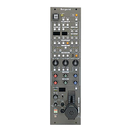
OCP-399
OPERATION CONTROL PANEL
OPERATION MANUAL
HEAD
POWER
VF
PANEL
OFF
POWER
ENABLE
CAM
COLOR
PM IND
POWER
MATCH
MASTER
/PAGE
HOLD
MENU
AUTO SETUP
LEVEL
SKIN HUE
QUICK
START
AWB
ABB
MODE SWITCH
SUPER
COLOR
MATRIX
KNEE
CAP
BARS
CAL
CORR
1 2 3
L
M
H
CUSTOM COLOR
OFF
OFF
EFF1
EFF2
BLK STRETCH
BLK
-11
-7 -3 +3 +7 +11
SHUTTER
SUPER V
GAMMA
ON
(%)
ON
VAR.
GAMMA
GAIN(dB)
1 0 0 0
0
4
5
+ 1 2
.
FILTER
HEAD
1
2
3
4
5
A
B
C
D
E
ND
CC
EFF
SCENE FILE
STORE
1
2
3
4
5
6
7
8
DTL
SKIN
C.SAT
GAMMA
KNEE PT.
SLOPE
SOFT
SKIN
COLOR
AUTO
DTL
DTL
SAT
KNEE
LOCK
GAIN
BLACK
PED
FLARE
MASTER
CLR
FLARE
TALLY
AUTO
LENS EXT
MON SEL
B
RGB
KNOB
G
Y
FREE
R
ENC
IRIS
RANGE
SENS
CLS
OPEN
IRIS
FULL
±1
±2
CALL
CABLE
OPEN
SHORT
ALARM
PED
Advertisement
Table of Contents

Subscribe to Our Youtube Channel
Related Manuals for Ikegami OCP-399


Summary of Contents for Ikegami OCP-399
- Page 1 KNEE PT. SLOPE SOFT SKIN COLOR AUTO KNEE LOCK GAIN BLACK FLARE MASTER FLARE TALLY AUTO LENS EXT MON SEL KNOB FREE IRIS RANGE SENS OPEN IRIS FULL ±1 ±2 CALL CABLE OPEN SHORT ALARM OCP-399 OPERATION CONTROL PANEL OPERATION MANUAL...
-
Page 2: Operation Control Panel
AUTO KNEE LOCK GAIN BLACK FLARE MASTER FLARE TALLY AUTO LENS EXT MON SEL KNOB FREE IRIS RANGE SENS OPEN IRIS FULL ±1 ±2 CALL CABLE OPEN SHORT ALARM OCP-399 OPERATION CONTROL PANEL OPERATION MANUAL 0403 1st Edition (U) (E) - Page 3 We reserve the copyright on the software we create. No part of this publication may be modifi ed or reproduced in any form, or by any means, without prior written permission from Ikegami No part of this publication may be modifi ed or reproduced in any form, or by any means, without prior written permission from Ikegami Tsushinki Co., Ltd.
-
Page 4: Safety Precautions I
(once every 3 years or 8000 hours use) is recommended to extend the life and safe use of this product for a long time. Please contact Ikegami's sales and service centers or Techno Ikegami Co., Ltd. for the regular maintenance and repair of our products. -
Page 5: How To Use Operation Manual
HOW TO USE OPERATION MANUAL The OCP-399 OPERATION CONTROL PANEL OPERATION MANUAL is intended to describe how to operate the OCP-399. This manual is written for readers with a basic knowledge of handling broadcast cameras and Base Station (BS), so technical terms are not explained here. -
Page 6: Table Of Contents
4.1 Alarm Lamp Flashes ............4-1 OCP-399 0403 VOL1 (U) (E) - Page 7 5.4 External Dimensions Diagram ........... 5-3 OCP-399 OCP-399 0403 VOL1 (U) (E)
-
Page 8: Name And Function
LENS EXT indicator FILTER switches TALLY indicators SCENE FILE switches PS CONT connector (OCP-399U only) MODE switches/VR controls COLOR MATCH connectors IRIS indicator COMMAND connector AUTO IRIS switch PREVIEW connector JOYSTICK (IRIS, M-PED) (PREVIEW switch) OCP-399 0403 VOL1 (U) (E) OCP-399... - Page 9 Pressing the switch again while executing setups will cancel the execution. When the execution ends, the lamp goes OFF. When the execution fails, the START switch fl ashes. After confi rming the failure, press the START switch again to clear the failure. OCP-399 OCP-399 0403 VOL1 (U) (E)
- Page 10 LED display indicates the current setting value. Normally, set to "0.45." - GAIN switch Select Master Gain using the UP/DOWN switch. One of the following values can be selected: -3, 0, +3, +6, +9, +12, +18, OCP-399 0403 VOL1 (U) (E) OCP-399...
- Page 11 fl are. If the fl are control is selected, the MASTER FLARE indicator lights when the OCP is connected to the camera which supports MASTER FLARE, indicating the MASTER FLARE control for G channel is active. OCP-399 OCP-399 0403 VOL1 (U) (E)
- Page 12 : In this mode, the position of the IRIS RANGE control and JOYSTICK directly affects Open and Close of the IRIS. 16 CALL switch Lights the R TALLY of the camera head and BS. OCP-399 0403 VOL1 (U) (E) OCP-399...
- Page 13 Connect the COLOR MATCH cable. Bridge-connecting multiple OCPs with the COLOR MATCH cables enables the color match operation. 28 COMMAND connector Connect the CP cable. 29 PREVIEW connector Output connector for the PREVIEW switch (see item 15). OCP-399 OCP-399 0403 VOL1 (U) (E)
-
Page 14: Installation And Connection
KNEE PT. SLOPE SOFT SKIN COLOR AUTO KNEE LOCK GAIN BLACK FLARE MASTER FLARE TALLY AUTO LENS EXT MON SEL KNOB FREE IRIS RANGE SENS OPEN IRIS FULL ±1 ±2 CALL CABLE OPEN SHORT ALARM OCP-399 0403 VOL1 (U) (E) OCP-399... -
Page 15: Ocp Connection
Connect the COMM connector of the OCP to the REMOTE connector on the right side of the camera head with the REMOTE cable. Side View of the Camera REMOTE connector FUSE(5A) REMOTE COMM connector OCP-399 OCP-399 0403 VOL1 (U) (E) - Page 16 The BS-388 for EU area does not use the POWER CONT cable. P.S CONT connector COMM connector POWER CONT POWER CONT cable connector OCP/CCP connector CP cable maximum 300 m Rear view of the BS OCP-399 0403 VOL1 (U) (E) OCP-399...
- Page 17 Connect the COLOR MATCH connector of the OCP with the COLOR MATCH cable by bridge connection. As the COLOR MATCH connector IN and OUT cannot be differentiated, the connecting position is free. COLOR MATCH connector OCP-1 OCP-2 OCP-3 COLOR MATCH cable (maximum length 10m) OCP-399 OCP-399 0403 VOL1 (U) (E)
-
Page 18: Connector Pin Function
HET TRX (+) Color matching control signal output (+) HET TRX (-) Color matching control signal output (-) HET GND Ground for Color matching control signal _ N. C (spare) _ N. C (spare) OCP-399 0403 VOL1 (U) (E) OCP-399... - Page 19 DC + 12 V power supply from BS + 12 V RET Ground for DC + 12 V power supply INCOM TALK INCOM microphone signal to BS INCOM RECEIVE INCOM receiver signal from BS OCP-399 OCP-399 0403 VOL1 (U) (E)
-
Page 20: Operation
CALL CABLE OPEN SHORT ALARM 3.1.2 BS-388 for EU Area Turn ON/OFF the power using the BS MAIN POWER switch. The CAM POWER switch on the OCP can only turn ON/OFF the HEAD POWER. OCP-399 0403 VOL1 (U) (E) OCP-399... -
Page 21: Operation Check
[ PAL ] BLACK FLARE MASTER FLARE TALLY AUTO MONITOR SELECT switch LENS EXT MON SEL KNOB FREE “ENC” IRIS RANGE SENS OPEN IRIS ±1 ±2 FULL CALL CABLE OPEN SHORT ALARM 100% -20% OCP-399 OCP-399 0403 VOL1 (U) (E) -
Page 22: Checking With Test Pulse
“R”, “G”, “B”, “RGB”, “Y” IRIS RANGE SENS (SEQ: R, G, B) OPEN IRIS FULL ±1 ±2 CALL CABLE OPEN SHORT ALARM 3.2.3 Checking Images on Charts Shoot an external chart and check that the image is normal. OCP-399 0403 VOL1 (U) (E) OCP-399... -
Page 23: Auto Setup
(The convergence value for FULL auto setup can be selected from INT (internal reference) and EXT (external reference). At shipment, this reference fi le values are created in the memory. To change the reference fi le values, there is a need to create fi les. OCP-399 OCP-399 0403 VOL1 (U) (E) -
Page 24: Quick Auto Setup
Set the control VR to the center position. Upon completing quick auto setup, the VR value at that time will be read. If the VR is not at the center position, only one side of the control may be effective. OCP-399 0403 VOL1 (U) (E) OCP-399... -
Page 25: Auto Setup
When the FILTER HEAD switch is lit, press the switch to pass control right of the fi lter to the panel. If fl ashing, it means that the fi lter is in the manual mode. 3 Set the following controls to the center position: OCP-399 OCP-399 0403 VOL1 (U) (E) -
Page 26: Awb (Auto White Balance)
If the R, G, B GAIN controls on the OCP are not at their center positions, only one side of the control may be effective as a result of AWB. The one-sided control can be corrected by setting the VR back to the center position while pressing the KNOB FREE button. OCP-399 0403 VOL1 (U) (E) OCP-399... -
Page 27: Abb (Auto Black Balance)
To execute ABB , press the QUICK switch and then the ABB switch. AUTO BLACK SHADING will be executed. PED, BLACK SET and BLACK SHADING are executed for the AUTO BLACK SHADING. (PED and BLACK SET are also executed when auto black balance is executed.) OCP-399 OCP-399 0403 VOL1 (U) (E) -
Page 28: Operation Procedures
2 Set the VARIABLE SHUTTER switch to “ON” and set the variable shutter mode. 3 Set the desired shutter speed using the UP/DOWN switches. 4 To cancel the variable shutter mode, set the VARIABLE SHUTTER switch and SHUTTER ON/OFF switch to “OFF”. OCP-399 0403 VOL1 (U) (E) OCP-399... -
Page 29: Improving Reproducibility Of Low Luminance Level Part (Black Press/Black Stretch)
1 Press the SOFT DTL switch to “ON”. 2 Shoot the grayscale chart and monitor the signals on the WFM. 3 Turn the DTL control, and adjust so that the edge at the high contrast area becomes appropriate. OCP-399 OCP-399 0403 VOL1 (U) (E) - Page 30 OFF using the SKIN DTL switch, use it for setting. The set SKIN DTL value is also recorded as data in the scene fi le (The scene fi le also records the ON/OFF state). OCP-399 0403 VOL1 (U) (E) OCP-399...
-
Page 31: Correcting Color Temperature For Multiple Cameras (Color Matching)
5 Adjust the RGB GAIN and CC fi lter of the master camera. The slave camera also changes accordingly. 6 When color matching ends, press the MASTER and COLOR MATCH switches to turn them OFF. OCP-399 OCP-399 0403 VOL1 (U) (E) -
Page 32: Creating Scene Files
MANU KNEE POINT TOTAL/R, G, B AUTO KNEE POINT TOTAL/R, G, B MANU KNEE SLOPE TOTAL/R, G, B AUTO KNEE SLOPE TOTAL/R, G, B DTL LEVEL DTL SKIN DTL LEVEL COLOR SATURATION VARIABLE SHUTTER OCP-399 0403 VOL1 (U) (E) OCP-399... - Page 33 When reading the scene file, if the control on the OCP is not at the center position, only one side of the control may function. To resolve this problem, be sure to set the control to the center, because the control may not be effective until it is turned past the center even after loading. OCP-399 OCP-399 0403 VOL1 (U) (E)
-
Page 34: Menu Remote
OFF when the TALLY is ON. Reference: Depending on the BS model, some cable extension adaptor is not displayed on the menu unless the BARS switch is set to ON. Refer to the manuals for each BS model. OCP-399 0403 VOL1 (U) (E) OCP-399... -
Page 35: Internal Switch Settings
Set the DIP switches on the I/F BOARD. When a switch is set to the position in the direction of the arrow shown below, the switch is ON. DIP switches Arrow indicates “ON” I/F BOARD OCP-399 OCP-399 0403 VOL1 (U) (E) - Page 36 MCP, these items will be automatically set to ON and able to be controlled from the OCP after the control rights are shifted to the OCP. ON : Does not activate automatic control function. OFF : Activates automatic control function. OCP-399 0403 VOL1 (U) (E) OCP-399...
- Page 37 OCP-399 OCP-399 0403 VOL1 (U) (E)
-
Page 38: Troubleshooting
VF and PM (for 20 seconds) to enable check. Even if the indicator is not fl ashing, setting the PM IND/PAGE switch on the OCP to “ON” will display the self-diagnosis information on the VF and PM in the same way. OCP-399 0403 VOL1 (U) (E) OCP-399... - Page 39 Fan in the BS or CCU has stopped. Genlock Synchronization signal status BS to Head Comm Command from the BS or CCU to the camera head Head to BS Comm Command from the camera head to the BS or CCU OCP-399 OCP-399 0403 VOL1 (U) (E)
- Page 40 : 57 to 150 Hz 19.6133 m / S (2G) The test is conducted once for each of X, Y, and Z axes with 1 octave (i.e., 57 to 150 Hz) in 1 minute. (4) EMI FCC class A OCP-399 0403 VOL1 (U) (E) OCP-399...
- Page 41 OCP-399 OCP-399 0403 VOL1 (U) (E)
- Page 42 5. SPECIFICATIONS 5.4 External Dimensions Diagram ±1.5 ±0.5 6.25 ±5 355.5 4-φ4.8 Switch Guard P.S CONT COLOR MATCH PREVIEW COMM OCP-399 0403 VOL1 (U) (E) OCP-399...
- Page 43 Ikegami Tsushinki Co., Ltd. - All rights reserved. Reproduction or duplication, without permission of Ikegami Tsushinki Co., Ltd. of editorial or pictorial content in whole or in part, in any manner, is prohibited. - Specifi cations and design are subject to change without prior notice.
- Page 44 37 Brook Avenue, Maywood, New Jersey 07607, U.S.A. Phone: (201) 368-9171, Telex: 219034 ITCNJ UR, Fax: (201) 569-1626 Ikegami Electronics (Europe) GmbH Ikegami Strasse 1, 41460 Neuss 1, F.R. Germany Phone: (02131) 123-0, Telex: 17-2131365=IKE, Fax: (02131) 102820 Property of :...
Need help?
Do you have a question about the OCP-399 and is the answer not in the manual?
Questions and answers