
Subscribe to Our Youtube Channel
Related Manuals for Ikegami OCP-10


Summary of Contents for Ikegami OCP-10
- Page 1 Products conforming to RoHS directive OCP-10 Operation Control Panel Operation Manual...
- Page 3 Products conforming to RoHS directive OCP-10 Operation Control Panel Operation Manual 1501 2 Edition(U) (E)
- Page 4 Copyright © 2014 – 2015 Ikegami Tsushinki Co., Ltd We reserve the copyright on the software we create. No part of this publication may be modified or reproduced in any form, or by any means, without prior written permission from Ikegami Tsushinki Co., Ltd.
- Page 5 PRODUCTS CONFORMING TO RoHS DIRECTIVE Following products described in this manual are products conforming to RoHS directive. • OCP-10 Operation Control Panel Products conforming to RoHS directive include products that do not contain specified hazardous substances such as lead, mercury, cadmium, hexavalent chromium, polybrominated biphenyl (PBB) and polybrominated diphenyl ether (PBDE) in electrical and electronic equipment excluding following exemption applications based on the EU directive (Directive 2002/95/EC).
- Page 6 PRODUCTS CONFORMING TO RoHS DIRECTIVE 8. Cadmium plating except for applications banned under Directive 91/338/EEC amending Directive 76/769/EEC relating to restrictions on the marketing and use of certain dangerous substances and preparations 9. Hexavalent chromium as an anti-corrosion of the carbon steel cooling system in absorption refrigerators 10.
- Page 7 MAINTENANCE OF PRODUCTS CONFORMING TO RoHS DIRECTIVE MAINTENANCE OF PRODUCTS CONFORMING TO RoHS DIRECTIVE Work with care about followings for maintenance of products conforming to RoHS directive. · For products conforming to RoHS directive, the letter “E” is appended at the end of the serial number on the label.
- Page 8 INFORMATION TO THE USER This equipment has been tested and found to comply with the limits for a Class A digital device, against harmful interference when the equipment is operated in a commercial environment. This equipment generates, uses, and can radiate radio frequency energy and, if not installed and used in accordance with the instruction manual, may cause harmful interference to radio communications.
-
Page 9: Safety Precautions
SAFETY PRECAUTIONS SAFETY PRECAUTIONS This manual describes the precautions using various pictorial symbols for you to use the product safely. Please read these precautions thoroughly before use. The symbols and meanings are as follows:... - Page 10 SAFETY PRECAUTIONS...
- Page 11 HOW TO READ THE OPERATION MANUAL HOW TO READ THE OPERATION MANUAL This page explains general notes on reading the OCP-10 Operation Manual, and the symbols and notations used in the manual. Indicates OCP-10 Operation Control Panel.
-
Page 13: Table Of Contents
OCP-10 Operation Control Panel OPERATION MANUAL CONTENTS 1. Outline .................. 1 1.1 Outline ....................1 1.2 Features....................1 1.3 External View ..................2 2. Name and Function of Each Part ........5 2.1 OPT Indicator ..................7 2.2 GAIN Controls ..................7 2.3 F. - Page 14 2.17 RELATIVE Switch ................10 2.18 FULL Switch ..................10 2.19 AUTO Switch ..................10 2.20 IRIS Indicator ................... 10 2.21 IRIS Control ..................11 2.22 PREVIEW Switch ................11 2.23 KNOB FREE Switch ................. 11 2.24 CALL Switch ..................11 2.25 HEAD PWR Indicator ...............
- Page 15 6. Ethernet (Option) ............... 23 6.1 Conceptual Diagram of Network ............23 6.2 Ethernet connection method ............24 7. Panel Configuration ............25 7.1 Panel Configuration Menu ..............25 7.2 List of Panel Configuration Settings ..........27 7.3 List of Tally Guard Functions ............28 7.4 IRIS Position Adjustment Function ..........
-
Page 17: Outline
1. Outline 1.1 Outline The OCP-10 is an operation control panel that is used by connection to a BS (Base Station) or CCU (Camera Control Unit) or Camera Head. 1.2 Features Knob Free function is adopted The OCP-10 adopts the knob free function which combines the advantages of absolute control of potentiometers with the advantages of relative control of rotary encoders. -
Page 18: External View
1.3 External View 1) VR TYPE Option... - Page 19 2) Slim TYPE...
- Page 20 3) JS TYPE Option...
-
Page 21: Name And Function Of Each Part
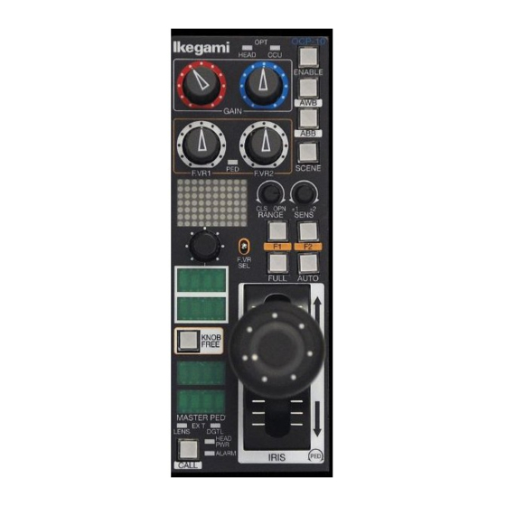
2. Name and Function of Each Part This section describes the name and function of various parts. OPT indicator IRIS RANGE/SENS control GAIN control RELATIVE switch (VR TYPE only) F.VR control (user function) FULL switch ENABLE switch AUTO switch AWB switch IRIS indicator ABB switch IRIS control... - Page 22 OPT indicator IRIS RANGE/SENS control GAIN control - F.VR control (user function) FULL switch ENABLE switch AUTO switch AWB switch IRIS indicator ABB switch IRIS control SCENE file switch PREVIEW switch (JS TYPE only) F.VR function selector switch KNOB FREE switch EXT indicator CALL switch F (user function) switch...
-
Page 23: Opt Indicator
2.1 OPT Indicator It indicates the transmission level when optical fiber cable is used. The CCU indicator indicates the optical level from the camera head to the CCU. The HEAD indicator indicates the optical transmission level from the CCU to the camera head. Each indicator indicates the optical transmission level in five stages by lighting on/blinking/lighting off three indicators with colors of green, amber, or red. -
Page 24: Enable Switch
2.4 ENABLE Switch It enables OCP operation. When the switch is lit on, control from the OCP is available. 2.5 AWB Switch It performs AWB (Auto White Balance). When AWB is completed, the lamp lights off. When AWB fails, the lamp blinks. After checking the failed state, press the blinking switch again to reset the failed state. -
Page 25: F.vr Function Selector Switch
2.8 F.VR Function Selector Switch This switch allows allocating functions to F.VR1 and F.VR2. Reference : Refer to "3. F.VR Controls" for the method for user setting. In addition during camera head menu operation, switching the command that is sent to the camera head during the rotary switch rotation is available. Reference : Refer to "4.2.2 Menu Operation from OCP"... -
Page 26: Master Ped Indicator
2.14 MASTER PED Indicator It indicates the adjusted value of the master pedestal. 2.15 MASTER PED Control It controls the master pedestal. 2.16 IRIS RANGE/SENS Control RANGE control It sets the iris F stop at the center position of the IRIS Control. SENS control It sets the control range of the IRIS Control. -
Page 27: Iris Control
2.21 IRIS Control It controls the lens iris. During AUTO IRIS, it controls the iris by approximately +/- 1 stop. 2.22 PREVIEW Switch It outputs a PREVIEW signal from the EXT (PREVIEW) connector and from the BS hub and BS/CCU connected to the network. Typically used to control a preview switcher. -
Page 28: Command Connector
2.29 Connector for LAN (Option) It connects to an Ethernet-compatible BS/CCU or hub via a LAN cable. 2.30 ICCP/Ether Selector Switch (Option) It switches between Ikegami command connection and Ethernet connection. ICCP : For Ikegami command connection via the command connector... -
Page 29: F.vr Controls
3. F.VR Controls The OCP-10 provides several pages of functions which can be allocated to the F.VR controls by operating the F.VR SEL function selector switch. In addition, functions which are not needed can be removed by deleting pages from sequence available when operating the F.VR SEL switch. -
Page 30: F.vr Control
3.2 F.VR Control Page Setting [Shifting to the setting mode on the operation page] [操作ページ設定モードへの移行] Volumes available for function 機能割当て可能ボリューム(F.ボリューム) allocation (F. Volume) Item display 項目表示 Upper section: F.VR1 allocation function 上段:F.VR1割当て機能 Lower section: F.VR2 allocation function 下段:F.VR2割当て機能 When pressed simultaneously, Valid/invalid 同時押下で、F.ボリュームページの... -
Page 31: List Of Pages For F.vr1 And F.vr2
When the F.VR control function selector switch is pressed up or down for approx. 2 seconds together with pressing Knob Free, the mode for including and deleting pages opens. In this setting mode, when the F.VR control function selector switch is operated, the F.VR1 function is indicated at the upper section of the item indicator, and F.VR2 function is indicated at the lower section of the item indicator as a page information. -
Page 32: Switch
F. Switch The OCP-10 allows the user to assign the function of two switches, the F1 and F2 switches. 4.1 F. Switch Customize Function Item indication Upper section : Allocated switch (F1 or F2) Lower section : Allocated function Turning: Selecting function for allocation Pressing: Ending the F. -
Page 33: List Of Switch Functions
When turning the rotary switch, functions to be allocated to the F. switch can be selected. * As soon as a function is allocated to the F switch, the state of the allocated function is reflected on the LED. When the F. switch is pressed in the F. switch customize mode, turning the allocated function on and off is possible. -
Page 34: Vr Clear Operation
VR Clear Operation 4.2.1 Allocating "VR Clear" to the F switch will clear the data that the user adjusted. Item Clearing Action R/B GAIN Always cleared F.VR1, F.VR2 Allocated function data is cleared. Always cleared MASTER PED Aligns the IRIS control position and the lens IRIS IRIS position (including RANGE/SENSE) -
Page 35: Menu Operation From Ocp
Menu Operation from OCP 4.2.2 When "MENU ON/OFF" is allocated to the F. switch, the camera head and the BS/CCU menu can be operated from the OCP. [Menu Operation] Menu select command switching (SEL/NEXT) (F.VR function selector switch) Rotating: Up/Down navigation Pressing: Push Set to enter sub-menu /change setting Item display... -
Page 36: Rotary Switch
5. Rotary Switch The rotary switch enables various functions to be selected and set. 5.1 Selection and Setting of Rotary Switch Functions Item indication Turning : Selection of items and parameters Pressing : Setting of items and parameters Turn the rotary switch to select the item to be controlled in the upper section of the item indicator. -
Page 37: List Of Rotary Switch Functions
5.2 List of Rotary Switch Functions Indicated Item Function Remarks Letters Select 1 to 6 Select A to F I to VI Select -6, -3, 0, +3, +6, +9, +12, +18, Step Gain Gain Select +24, +30, +36, +42, +48, +54 OFF, 0.90, 0.80, 0.70, 0.60, 0.55, 0.50, Step Gamma Gamm... -
Page 38: Scene File Setting Method
5.3 SCENE FILE Setting Method With the rotary switch scene files 1 to 8 can be selected. Pressing the SCENE switch enables saving and loading of the scene file which has been selected. [SCENE FILE saving method] Turn the rotary switch to select "SCENE" at the upper section of the indicator. Press the rotary switch and select the FILE number to be set, shown at the lower section of the indicator. -
Page 39: Ethernet (Option)
6. Ethernet (Option) As an optional function, the OCP-10 can be operated using an Ethernet connection. This section describes the concept of Ethernet operation and the connection method. 6.1 Conceptual Diagram of Network Ethernet not supported BS/CCU Ethernet supported BS/CCU... -
Page 40: Ethernet Connection Method
Note : When the Ethernet hub supports POE+ (Power Over Ethernet), powering the OCP-10 via the Ethernet cable becomes available. When the OCP-10 is used in Ethernet configuration, it is necessary to set the IP Address, Subnet Mask, and Default Gateway. ... -
Page 41: Panel Configuration
7. Panel Configuration The OCP-10 has many functions, and its operation and settings can be setup to meet the user’s requirements. 7.1 Panel Configuration Menu Item indication When pressed simultaneously, panel configuration is indicated. Press the rotary switch and the Knob Free switch simultaneously for approximately 2 seconds. - Page 42 Press the rotary switch and the setting of the selected item starts blinking. Next the setting can be changed by turning the rotary switch. When the desired setting is displayed, push the rotary switch. Exit the Panel Configuration menu by selecting Exit and pressing the rotary switch.
-
Page 43: List Of Panel Configuration Settings
7.2 List of Panel Configuration Settings Item Function Set value Remarks ABS (Absolute value Controlled with the absolute value control)*1 IRIS CONT Select REL (Relative value Controlled with the relative value control) 6 dB *1 The control range is ± 6 dB. GAIN RANGE Select 3 dB... -
Page 44: List Of Tally Guard Functions
7.3 List of Tally Guard Functions Switches can be prohibited when the ON-AIR by setting the ON-AIR tally guard function. Panel Configuration Panel Configuration Setting Setting Function limited Function limited Item Item PANEL ENABLE ○ ○ - BARS ON/OFF ○ ○... -
Page 45: Iris Position Adjustment Function
It is possible that the lens iris is not at the OPEN/CLOSE end when the OCP iris is at the OPEN/CLOSE end, even under full range operation. The OCP-10 has a function to recognize the OPEN/CLOSE end positions of the iris in the panel configuration menu, and correct the difference with the camera head lens iris value. -
Page 46: Program Number Indication
Select "ADJUST MODE" under the panel configuration menu. On the character indicator, "POS1" is indicated at the upper section and "POS2" at the lower section. Align the IRIS position to the OPEN end and press the rotary switch. ("POS1" indicated at the upper section of the character indicator changes to "OK.") Align the IRIS position to the CLOSE end and press the rotary switch. -
Page 47: Limit Functions (Control Depth)
7.6 Limit Functions (Control Depth) By selecting the operation from two modes, [COMPLETE or BASIC] under "USER MODE" of the panel configuration menu, the selection for the F1 and F2 switches, as well as, the selection for the rotary switch can be limited. All functions are available in the COMPLETE(indication: COMP) mode, and limited functions are available in the BASIC(indication: BSIC) mode as indicated in the lists "7.6.1 and 7.6.2". -
Page 48: List Of Limited Functions For Rotary Switch
7.6.2 List of Limited Functions for Rotary Switch Item Function Mode Select BASIC Select BASIC Select BASIC Step Gain Select BASIC Step Gamma Select Gamma Mode Select BLK STR/PRS Select BASIC AWB ch Select Shutter Mode Select BASIC Shutter Speed Select BASIC Var C.Temp... -
Page 49: Setting Ip Address/Subnet Mask/Default Gateway
7.7 Setting IP Address/Subnet Mask/Default Gateway [Ethernet setting menu] When operating the OCP-10 by Ethernet connection, it is necessary to set the IP Address/Subnet Mask/Default Gateway of OCP itself and the IP Address of the BS/CCU to be controlled. Set each item under "Ethernet" of the panel configuration menu. - Page 50 [Item setting mode] It sets each of OCP and BS. When a setting item is selected from the Ethernet setting menu, the indication becomes as shown in the following drawing. The boxes in the upper section indicate the image of IP address in four digits. (Ex.: 192/168/1/100) Turning the rotary switch moves the black box in the upper section of the character indicator.
-
Page 51: Troubleshooting
F. switch. Refer to "4. F. Switch" for the allocation method. 8.2 Adjustment of IRIS Friction The OCP-10 has an adjustment for joystick iris friction. Friction can be adjusted by inserting a hexagon wrench through the side plate and turning clockwise/counterclockwise (effective only with JS TYPE). Turning clockwise will increase the friction, and turning counterclockwise will decrease the friction. -
Page 52: Initialization
8.3 Initialization The OCP-10 can return the panel configuration settings, F. VR operation page setting, and F. switch customize setting to the default setting (state at the time of shipping from the factory). It indicates the progress of internal memory clear process. -
Page 53: Specification
9. Specification 9.1 Rating Power supply +12V (+9V to 18V) Consumed power 3W Max. cable length 300m (CP cable) 100m(LAN cable) Operation temperature 0°C to +45°C Storage temperature -25°C to +60°C Operation humidity range 30% to 90% (no condensation) -
Page 54: Pin Function Of External Connector
9.2 Pin Function of External Connector COMMAND Connector 9.2.1 SEAT Connector to input/output various signals between BS/CCU and CP HUB. Main body side: PRC05-R8M Cable side: PRC05-199P9-8F (8-pin female plug) or equivalent Insert side External Pin No. Name Function Direction Interface Serial command from BS/CCU to OCP HED (+) -
Page 55: Ext Connector
EXT Connector 9.2.2 It is a connector for extension. SEAT 座 ① ⑤ ④ ③ ② Main body side : D-sub 15-pin (socket) Cable side : D-sub 15-pin (pin), Inch screw ⑩ ⑨ ⑧ ⑦ ⑥ ⑮ ⑫ ⑭ ⑬ ⑪... - Page 56 1 Preview output When the PREVIEW switch is pressed, PV (-) short-circuits with COM. When the PREVIEW switch is not pressed, PV (+) short-circuits with COM. 2 External input/output The external input/output function is provided. It has the pin configuration that can be used for both input and output;...
- Page 57 External Input 外部入力 Name Function External Interface 名 称 機 能 外部インターフェース Pin No. ピン番号 R TALLY Rタリー入力 R tally Input G tally Input G TALLY Gタリー入力 Y tally Input Y TALLY Yタリー入力 ENABLE イネーブル入力 Enable Input 信号接地 Signal : The input circuit has a simple configuration. When the cable connected Caution to the system is long or when there is a potential difference, the operation might fail.
- Page 58 3 Program Number Output Output the camera program number by a three-wire type serial signal (RS-485). By using this output, the program number can be indicated on a tally panel, etc. The data is sent from MSB. Three-wire type serial data format 3線式シリアルデータ形式...
-
Page 59: Changing Information
10. Changing Information... - Page 61 OCP-10 OPERATION CONTROL PANEL Operation Manual 2nd Edition: Issued in JAN. 2015 by Ikegami Tsushinki Co., Ltd. All or no part of this document may be photocopied or ■ reproduced in any form without the prior written consent of ABC Inc.
- Page 63 Ikegami Tsushinki Co., Ltd. 5-6-16, Ikegami, Ohta-ku, Tokyo, 146-8567, Japan Phone : +81-(0)3-5700-4114 Fax : +81-(0)3-5748-2200 E-Mail : info_e@ikegami.co.jp : http://www.ikegami.co.jp/en/ Ikegami Electronics (U.S.A.),Inc. 37 Brook Avenue, Maywood, New Jersey 07607, U.S.A. Phone : +1-201-368-9171 Fax : +1-201-569-1626 E-Mall : engineering@ikegami.com, service@ikegami.com : http://www.ikegami.com...
Need help?
Do you have a question about the OCP-10 and is the answer not in the manual?
Questions and answers