Table of Contents
Advertisement
Quick Links
Advertisement
Table of Contents

Related Manuals for Ikegami MCP-300


Summary of Contents for Ikegami MCP-300
- Page 1 RoHS Compliant Products MCP-300 Master Control Panel Operation Manual...
- Page 3 RoHS Compliant Products MCP-300 Master Control Panel Operation Manual 1512 1 Edition (U) (E)
- Page 4 Copyright © 2015 Ikegami Tsushinki Co., Ltd We reserve the copyright on the software we create. No part of this publication may be modified or reproduced in any form, or by any means, without prior written permission from Ikegami Tsushinki Co., Ltd.
- Page 5 PRODUCTS CONFORMING TO RoHS DIRECTIVE Following products described in this manual are products conforming to RoHS directive. •MCP-300 Master Control Panel Products conforming to RoHS directive include products that do not contain specified hazardous substances such as lead, mercury, cadmium, hexavalent chromium, polybrominated biphenyl (PBB) and polybrominated diphenyl ether (PBDE) in electrical and electronic equipment excluding following exemption applications based on the EU directive.
- Page 6 ii MAINTENANCE OF PRODUCTS CONFORMING TO RoHS DIRECTIVE MAINTENANCE OF PRODUCTS CONFORMING TO RoHS DIRECTIVE Work with care about followings for maintenance of products conforming to RoHS directive. · For products conforming to RoHS directive, the letter “E” is appended at the end of the serial number on the label.
- Page 7 INFORMATION TO THE USER iii This equipment has been tested and found to comply with the limits for a Class A digital device, against harmful interference when the equipment is operated in a commercial environment. This equipment generates, uses, and can radiate radio frequency energy and, if not installed and used in accordance with the instruction manual, may cause harmful interference to radio communications.
- Page 8 iv SAFETY PRECAUTIONS This manual describes the precautions using various pictorial symbols for you to use the product safely. Please read these precautions thoroughly before use. The symbols and meanings are as follows:...
- Page 9 SAFETY PRECAUTIONS v...
- Page 10 vi SAFETY PRECAUTIONS...
- Page 11 Contents i HOW TO READ THE OPERATION MANUAL This section explains general notes on reading the MCP-300 Operation Manual, and the symbols and notations used in this manual. Notes on the Manual This manual is written for readers with a basic knowledge of handling a camera for broadcasting, CCU, MCP, etc.
-
Page 12: Table Of Contents
Contents MCP-300 Master Control Panel Operation Manual Table of Contents Overview ..................1 1.1. Description ..................1 1.2. Features ..................1 1.3. External View ................3 Name and Function of Each Part ..........4 2.1. Camera Control Section 1 ............. 4 2.2. - Page 13 Contents iii 3.6.5. Menu ................... 30 3.6.6. Name Entry ................. 30 3.7. MONI OUT .................. 31 3.7.1. Monitor Out Control ..............31 3.7.2. Monitor Out Setting ..............32 3.8. MCP SET ..................32 3.8.1. Control Depth ................32 3.8.2. Assign ..................35 3.8.3.
- Page 14 Direct menu jump ................ 55 8.4.3 Customize Control Depth ............56 8.4.4 Customize STD Function ............56 Firmware Update ................. 57 MCP-300 Update ................ 57 Update of Connected Devices ............. 58 Troubleshooting ................59 10.1 ALARM switch of MCP is flashing ..........59 10.2 Method to Reset the MCP ............
-
Page 15: Overview
7-inch color LCD with touch panel In addition to control equivalent to a conventional MCP (Maintenance Control Panel), more advanced settings are possible with the MCP-300 as a master control panel by operating the LCD screen. Also, the control panel is easy to use since you can optimize the menu items of the LCD screen. - Page 16 Please refer to the instruction manual of the camera for the operational Reference: functions. Do not connect the MCP-300 directly to the command connector of a camera Note: or BS/CCU because the power consumption is high.
-
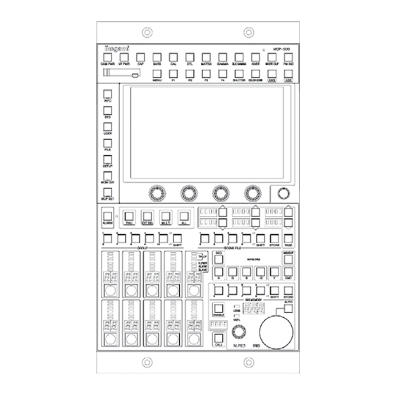
Page 17: External View
Overview 1.3. External View... -
Page 18: Name And Function Of Each Part
Name and Function of Each Part Name and Function of Each Part 1. Camera Control Section 1 4. WFM/PM Operation Section 2. LCD Operation Section 5. Iris / M. Ped Section 3. Camera Control Section 2 6. Camera Select Section 2.1. -
Page 19: Lcd Menu Operation Section
Name and Function of Each Part Switches Switches are used to operate some camera functions. Switch name Description CAM PWR Turns on/off the power to the camera head. VF PWR Turns on/off the power of the view finder. Turns on/off the CAP. BARS Turns on/off Color Bars. -
Page 20: Camera Control Section 2
Name and Function of Each Part STEUP Displays the screen to adjust the camera. MONI OUT Displays the screen to set and operate the optional video output board. MCP SET Displays the screen to setup the operation of the MCP. 2.3. -
Page 21: Camera Select Section
Name and Function of Each Part LENS indicator (top) Lights up when the extender of lens is turned on. DGTL indicator (bottom) Lights up when the digital extender of the camera is turned on. AUTO IRIS switch Sets the IRIS to Auto mode. (Operates when ENABLE is illuminated) IRIS indicator Displays the F stop of the lens. -
Page 22: Connector Panel
Camera No. indicator Displays the program number of the camera connected. Camera Select switch Selects a camera to be controlled. Note: The MCP-300 works in parallel to other control panels assigned to the same cameras. 2.7. Connector Panel 1. DC IN connector 6. - Page 23 Name and Function of Each Part ( ( 2) LAN1 connector Used to connect a LAN Since POE is supported, the power can be supplied here using a POE+ Switch. (3) LAN2 connector (currently not used) Used to connect a LAN Since POE is not supported, the power can not be supplied here.
-
Page 24: Lcd Menu
LCD menu LCD menu Various functions can be performed with the MCP-300 by using the menu and touch panel displayed on the LCD screen. The LCD screen allows you to check the ON/OFF status of camera functions and set various functions with switches displayed on the screen and adjusting the RE knobs. -
Page 25: Function Switch Info
LCD menu 3. Screen section 1. Function switch info 4. Title 2. Page select 5. Operation Selection 3.1.1. Function switch info The function names set for the Function switches are displayed. 3.1.2. Page select Displays switches when there are multiple pages. 3.1.3. -
Page 26: Camera Status
LCD menu 3.2.1. Camera Status The On/Off setting status of the camera functions is displayed on the LCD screen. The function items and the Camera Select switch numbers are displayed in vertical and horizontal directions, respectively. The status of all cameras in the same group can be checked during network operation. - Page 27 LCD menu Page 1 Item Standard setting Item Standard setting White Clip ON *1 BARS Knee ON *1 Auto Knee ON *1 FLARE Smooth Knee OFF *1 Gamma Mode NOR *1 Super Knee OFF *1 Step Gamma 0.45 *2 BLK/WHT Shade Black Gamma OFF *1 *1: Standard setting can be changed...
-
Page 28: Diagnostics
MCP-300. The firmware information is displayed in the following order, from left to right: MCP- 300, BS HUB, camera head, and BS/CCU. The version of FPGA equipped in this MCP-300 can be checked on the second page. -
Page 29: Mcp Setting
This can reset the camera to the standard setting by sending individual Manual Clear commands from the MCP-300. The ON/OFF items are reset to the standard settings that have been set in the MCP. The analog items are reset to the values that have been set by the Manual Set function. - Page 30 LCD menu *1 Standard setting can be changed.
-
Page 31: Recall Preset File Function
LCD menu *1 Standard setting can be changed. *1 Standard setting can be changed. 3.3.2. Recall Preset File function Recall Preset File will load a Preset File that has been saved in the backup memory in advance, by sending a special command from the control panel. Some Preset Files may contain factory data and user data depending on the specifications of the camera head and BS/CCU. -
Page 32: All Manual Set/Clear Function
LCD menu Please refer to the instruction manual of the camera head and BS/CCU Reference: connected for the procedure to save the user data. After loading a Preset File, the camera head and BS/CCU may be reset, Note: requiring enable restoration. If the camera head and BS/CCU are reset, the camera select of the MCP may be removed or the LCD screen may disappear. - Page 33 LCD menu The gray items are adjusted by rotary encoders.
- Page 34 LCD menu The gray items are adjusted by rotary encoders.
- Page 35 LCD menu The gray items are adjusted by rotary encoders.
- Page 36 LCD menu Detail, D/C Detail The Detail adjustment items are arranged. The [D/C Detail] page works only when the MCP is connected to a camera system with down converter. The gray items are adjusted by rotary encoders.
- Page 37 LCD menu The gray items are adjusted by rotary encoders.
- Page 38 LCD menu Color, D/C Color The color adjustment items are arranged. The [D/C Color] page works only when the MCP is connected to camera system with down converter. The gray items are adjusted by rotary encoders.
- Page 39 LCD menu The gray items are adjusted by rotary encoders.
- Page 40 LCD menu System The system adjustment items are arranged. The gray items are adjusted by rotary encoders. Lens The lens adjustment items are arranged. The gray items are adjusted by rotary encoders. Triax The Triax adjustment items are arranged. The gray items are adjusted by rotary encoders.
- Page 41 LCD menu Others Miscellaneous adjustment items with relatively low frequency in use are arranged. The gray items are adjusted by rotary encoders.
-
Page 42: On/Off Control
LCD menu 3.6.2. On/Off Control Controls the On/Off of the functions supported by the camera. The gray items are adjusted by rotary encoders. -
Page 43: Auto Setup
LCD menu The gray items are adjusted by rotary encoders. 3.6.3. Auto Setup Press the [AUTO SETUP] switch to perform auto setup (automatic adjustment) of the camera, and to set the reference value which is the target for auto setup. Auto Setup This page allows you to perform several auto setup processes. -
Page 44: Format
LCD menu When the Full Quick Auto Setup is running, “REGI” may be displayed on the Note: auto setup run display in the PM video. The Auto Hue Detect functions, Color Detail and Custom Color 1/2 are performed on the respective adjustment screens. Memo: Multi Auto Setup is run if the Auto Setup is run while the Multi switch is on and the slave camera is selected. -
Page 45: Moni Out
LCD menu Memo: The scene file name and Camera ID cannot be displayed and registered if the MCP is not connected to a camera that supports the function. If the Camera ID and scene file name are simultaneously set in multiple control panels, a malfunction may occur. -
Page 46: Monitor Out Setting
LCD menu 3.7.2. Monitor Out Setting Sets the information monitor function. is the initial settings when RAM Clear is performed. 3.8. MCP SET 3.8.1. Control Depth Sets the range of control access to one of the following four levels. The setting is protected by a password. - Page 47 LCD menu The prohibited functions are marked with lock icons. If these functions are pressed, the buzzer will sound and the operation will not be accepted. This is the same for the prohibited hard switches. If they are pressed, the buzzer will sound and the operation will not be accepted.
- Page 48 LCD menu Detailed information on the control depth Operation rights F F unction S S witch B B asic S S tandard E E xtended C C omplete Camera Status Diagnos INFO Firmware MCP Setting Others Clear to Standard (Basic) *1 Clear to Standard (Complete) *1 All Manual Clear *1 All Manual Set *1...
-
Page 49: Assign
3.8.2. Assign The settings of the Program No., the connection destination for the camera select, and the ARC ID and IP address of this MCP-300 can be performed from the LCD screen. Progaram No Sets the number to be displayed on the camera No. indicator. -
Page 50: Panel Config
Reference: Please refer to "6. Panel Configuration" for more details. 3.8.4. User Preset The MCP-300 has a user function that can customize the operation menu of the panel. Up to five pages of user screen with the same format as the Camera Control screen can... -
Page 51: Preset Files
RAM Clear Resets the RAM status to the initial value. Logo Data Clear Resets the logo image to the initial setting (Ikegami logo). Changing the logo image is optional. 3.8.6. Camsel Setting Sets the enable/disable of the Camera Select from the LCD screen. If all switches in the same group are disabled, that group will not be displayed. -
Page 52: Camera Data Control
Camera Data Control 4. Camera Data Control Save the values adjusted by the MCP (manual set). Also reset to the saved values (manual clear). 4.1. Manual Set and Clear The procedures for manual set and manual clear are shown below. (1) Press the numerical values you want to apply manual set or clear on the User screen or Camera Control screen. -
Page 53: Iris Data Clear
Camera Data Control 4.4. Iris Data Clear When operating the iris on the MCP, you must turn on the ENABLE switch of the iris/pedestal control section. If the switch is turned off, the operation of iris is restricted. The data of the iris can be cleared when the switch is turned off. If the Iris Data Clear setting is turned on, pressing the IRIS/MASTER Note: PED enable switch to change from... -
Page 54: Camera Select
Example: Displays "03" instead of "103". 5.2. Camera Select Settings The MCP-300 has the capability to be shared by many cameras. Initially the Camera Select switches are setup sequentially, but the user can customize for any camera system to be assigned to any select switch by changing the assignment. -
Page 55: Camera Select Output
Reference: Please refer to "11.2. External Connector Pin Function" for the interface. 5.4. Camera Select Output Outputs the Camera Select of the MCP-300 to an external device. The external Camera Select Output is not based on the selection of the actual camera, but based on which Camera Select switch is selected. - Page 56 Camera Select LEFT & RIGHT (Select knob) UP & DOWN (Next knob) Blinking cursor A A ssignment setting Move the cursor to the place you want to assign and confirm. The assign setting is performed. Competing settings cannot be set on both the OCP side and CCU side. If there is an existing setting, that setting is automatically canceled.
-
Page 57: Procedure For Using A Memory Card
When using a memory card, insert the memory card into the slot, and press the [FILE] switch from the function switches on the left side of the LCD screen. Also, the version of firmware of the MCP-300 can be updated by using a memory card. Reference: Please refer to "8. Firmware Update" for more details. -
Page 58: Inserting And Removing A Memory Card
Procedure for Using a Memory Card 6.2. Inserting and Removing a Memory Card When using a memory card, lift up the left side of the slot cover and turn it clockwise. Slowly insert the memory card into the slot in the right direction (terminal side on the back and notch on the left bottom) until you hear a click sound. -
Page 59: Data Loading
“Clearing…” is displayed. When the process is completed, the buzzer sounds, and the window closes. Note that the data is deleted even if the file data type is different. Note: 6.7. Firmware Update Updates the version of firmware for the MCP-300, the connected camera, and BS/CCU... -
Page 60: Message Display
Procedure for Using a Memory Card 6.8. Message Display Various messages may be displayed when saving, loading and deleting are performed using a memory card. The messages are shown below. If an [ERROR] is displayed, press [OK] to cancel the display. WARNING Message Description... -
Page 61: Multi-Function
This function is active in all communication configurations. Memo: 7.3. Camera Information Display The MCP-300 can simultaneously display the ON/OFF status, etc. of all cameras in the same group. Reference: Please refer to "3.2.1 Camera Status” for more details. 7.4. Multi-control A lock icon is displayed on the switches on the screen that cannot be control by multi- control. -
Page 62: All Switch
Multi-function 7.5. ALL switch Select the ALL switch to simultaneously control all cameras in the group currently displayed. 7.5.1. On/Off Control (ALL) Controls the ON/OFF of the functions supported by the camera. Some of the items that can be controlled by the ALL function are different compared to controlling an individual camera. -
Page 63: Panel Configuration
Panel Configuration 8. Panel Configuration The MCP-300 has many functions, including operating methods and settings which can be changed according to your operation form and adjustment method. Select the MCP SET switch to the left of the LCD screen to call up the Panel Config screen. -
Page 64: Panel Configuration Setting
Panel Configuration Panel Configuration Setting The settings for the MCP operation can be set. "8.2Initialization of Settings" and "10.3Factory" *1 is initialized in... - Page 65 Panel Configuration "8.2Initialization of Settings " and "10.3Factory" *1 is initialized in *3 cannot be initialized. It is automatically initialized if abnormality is detected.
- Page 66 Panel Configuration "8.2Initialization of Settings" and "10.3Factory" *1 is initialized in...
- Page 67 Panel Configuration "10.3Factory" *2 is initialized in...
-
Page 68: On Air Tally Guard
Panel Configuration 8.3.1 ON AIR tally guard Sets the ON AIR tally guard to restrict switches during the ON-AIR tally. < < ON- - A A IR tally guard function list>... -
Page 69: Customize
Panel Configuration CUSTOMIZE The user can set the functions to be assigned to the UP/DOWN Select switches and Function switches. 8.4.1 UP/DOWN SEL Sets the UP/DOWN Select switches. 8.4.2 Function SW Function switches from F1 to F4 can be set. 8.4.2.1 Direct menu jump Assigns DJMP to F1 to F4 and displays the LCD screen that is set by the user when the... -
Page 70: Customize Control Depth
Panel Configuration 8.4.3 Customize Control Depth The functions included in the different control depths can be changed. Reference: Please refer to "3.8.1. Control Depth" for more details. 8.4.4 Customize STD Function The standard setting of the Camera Status displayed in Information can be changed. Reference: Please refer to "3.2. -
Page 71: Firmware Update
Firmware Update 9 Firmware Update The firmware of the MCP-300 and connected devices can be updated by using an SD memory card at the MCP. MCP-300 Update Press and hold the [STD] and [PM IND] switches for about 5 seconds. -
Page 72: Update Of Connected Devices
Update of Connected Devices The firmware of connected devices can be updated from the MCP-300. The update is performed only on devices supporting software update by command. Also the setting of the menu in the target device or the setting of an internal switch may be required to update. -
Page 73: Troubleshooting
10. Troubleshooting 10 Troubleshooting 10.1 ALARM switch of MCP is flashing The BS/CCU has a self-diagnostic function to monitor the BS/CCU itself and the camera for abnormalities. The function is activated at the same time as the BS/CCU MAIN POWER switch is turned on and is always active during operation. -
Page 74: Ram Data Break" Is Displayed
If this message is often displayed, the back-up RAM may be damaged. Note: 10.5 Trouble During Firmware Update If the power of MCP-300 is turned off during firmware update, perform the update process again for MCP-300. Reference: Please refer to "9.1. MCP-300 Update" for the method to update MCP-300. - Page 75 10. Troubleshooting L L imit on the Number of Connections Up to 8 MCP/OCPs can be connected to one BS/CCU. It does not work for 9 MCP/OCPs or more. Each MCP is counted as one regardless of the Camera Select status.
-
Page 76: Specifications
11. Specifications 11 Specifications 11.1 Ratings Power input +12V (+10V to +18V) Power consumption 13W (Standard) Max. cable length DC IN not used DC IN used MCP cable LAN cable 100m 100m Operating 0 to +45 temperature to +60 Storage temperature Operating humidity 30% to 90% (No condensation) -
Page 77: External Connector Pin Function
11. Specifications 11.2 External Connector Pin Function Connector seat A connector used to input/output signals with a Main unit side : PW-1624BA(09) Cable side : S-1624A Insertion side... - Page 78 11. Specifications EXT-1 Connector seat Insertion side Extension connector. Main unit side : D-sub 2 5-pin (female), inch socket Cable side : D-sub 2 5-pin (male), inch screw...
- Page 79 11. Specifications There are two modes for the external Camera Select of the MCP-300. One is Direct Mode that can support up to 10 cameras and the other is Combination Mode that can support up to 100 cameras. The external select is enabled when the Enable terminal (pin no. 15) is connected to GND.
- Page 80 11. Specifications External camera select (combination mode)
- Page 81 11. Specifications Camera select status output...
- Page 82 11. Specifications EXT-2 connector (not used) Extension connector. Connector seat Main unit side : D-sub 1 5-pin (female), Cable side : D-sub 1 5-pin (male), inch screw Insertion side...
- Page 83 11. Specifications DC IN connector Used to connect an external power source (+12V DC) to the MCP. Use this connector when the length of cable is long. Make sure to connect external power when an information monitor is used. Connector seat Main unit side: XLR-4-32 F-5 15-01 (SW) (JAE) Cable side:...
-
Page 84: Changing Information
12. Changing Information 12. Changing Information... - Page 85 Published in Ikegami Factory of Ikegami Tsushinki Co.,Ltd. All rights reserved. Reproduction or duplication, without permission of Ikegami Tsushinki Co., Ltd. of editorial or pictorial content in whole or in part, in any manner, is prohibited. Specifications and design are subject to change without prior notice.
Need help?
Do you have a question about the MCP-300 and is the answer not in the manual?
Questions and answers