Table of Contents
Advertisement
Quick Links
Advertisement
Table of Contents

Subscribe to Our Youtube Channel
Related Manuals for Ikegami OCP-300


Summary of Contents for Ikegami OCP-300
- Page 1 Products conforming to RoHS directive OCP-300 Operation Control Panel...
- Page 3 Products conforming to RoHS directive OCP-300 Operation Control Panel 1406 1st Edition (U) (E)
- Page 4 Copyright © 2010 Ikegami Tsushinki Co., Ltd We reserve the copyright on the software we create. No part of this publication may be modified or reproduced in any form, or by any means, without prior written permission from Ikegami Tsushinki Co., Ltd.
- Page 5 PRODUCTS CONFORMING TO RoHS DIRECTIVE Following products described in this manual are products conforming to RoHS directive. •OCP-300 Operation Control Panel Products conforming to RoHS directive include products that do not contain specified hazardous substances such as lead, mercury, cadmium, hexavalent chromium, polybrominated biphenyl (PBB) and polybrominated diphenyl ether (PBDE) in electrical and electronic equipment excluding following exemption applications based on the EU directive (Directive2002/95/EC).
- Page 6 ii MAINTENANCE OF PRODUCTS CONFORMING TO RoHS DIRECTIVE MAINTENANCE OF PRODUCTS CONFORMING TO RoHS DIRECTIVE Work with care about followings for maintenance of products conforming to RoHS directive. 1. Identification · For products conforming to RoHS directive, the letter “E” is appended at the end of the serial number on the label.
- Page 7 INFORMATION TO THE USER iii INFORMATION TO THE USER This equipment has been tested and found to comply with the limits for a Class A digital device, against harmful interference when the equipment is operated in a commercial environment. This equipment generates, uses, and can radiate radio frequency energy and, if not installed and used in accordance with the instruction manual, may cause harmful interference to radio communications.
-
Page 8: Safety Precautions
iv SAFETY PRECAUTIONS SAFETY PRECAUTIONS This manual describes the precautions using various pictorial symbols for you to use the product safely. Please read these precautions thoroughly before use. The symbols and meanings are as follows:... - Page 9 SAFETY PRECAUTIONS v...
- Page 10 vi SAFETY PRECAUTIONS...
- Page 11 HOW TO READ THE OPERATION MANUAL vii HOW TO READ THE OPERATION MANUAL This page explains general notes on reading the BSH-300 Operation Manual, and the symbols and notations used in the manual.
-
Page 13: Table Of Contents
OCP Setup ……………………………………………………………… … ………… 4-37 Operation of the Control Knob …………………………………………… …… ………… 5- 1 Camera Data Adjustment …………………………………………… … …………… 5- 1 Control Method with OCP-300 …………………………………………………… 5- 5 Reconnection Process …………………………………………… … ……………… 5- 6 Knob Free Function ………………………………………………………………… 5- 8... - Page 14 Contents Absolute Iris Control ………………………………………………… … ………………… 6- 1 Clearing the Iris Manual File ……………………………………………………… 6- 2 Auto Iris Operation ………………………………………………………………… 6- 2 Initial Mode …………………………………………………………………………… 6- 2 Relative Iris Control ……………………………………………………………………… 7- 1 Clearing the Data of Other Control Panel …………………… …… …………… 7- 1 Auto Iris Operation ………………………………………………...
- Page 15 Contents Standard Function ………………………………………………………………………… 13-1 Function Overview ………………………………………………………………… 13-1 Operation Procedure ……………………………………………………………… 13-5 Character Setting ………………………………………………………………………… 14-1 Setting the Camera Menu ………………………………………………………… 14-2 Setting the BARS TITLE …………………………………………………………… 14-3 Setting the Scene File Name …………………………………………………… 14-6 Setting the Camera ID ……………………………………………………………… 14-8 USER Menu …………………………………………………………………………………...
- Page 16 Trouble in Networking …………………………………………………………… 22-6 Specification ……………………………………………………………………………… 23-1 Ratings ……………………………………………………………………………… 23-1 Pin Function of External Connector …………………………………………… 23-2 Updating the Firmware …………………………………………………………………… 24-1 Updating OCP-300 ………………………………………………………………… 24-1 Updating the Firmware of the Connected Device …………………………… 24-6 Changing the Information ……………………………………………………………… 25-1...
-
Page 17: Overview
1. Overview 1-1 1. Overview 1.1 Overview This operation control panel is used in ARCnet that is connected to BS (Base Station)/CCU (Camera Control Unit) and CP hub or in Ethernet that is connected to a commercially available network hub with LAN cable. 1.2 Features Network compatible Besides the control via conventional serial command, the control via ARC network... - Page 18 1-2 1. Overview User customization function User can assign four function switches and two volumes to arbitrary selected functions. Some pages in the LCD screen can be arbitrarily configured by the user. Memory backup The status of this product can be easily reset to the factory setting or user setting. IRIS control IRIS control can be selected from volume (VR) or joy stick (JOY) for this product.
-
Page 19: External View
1. Overview 1-3 1.3 External view 1) VR TYPE... - Page 20 1-4 1. Overview 2) JOYSTICK TYPE...
-
Page 21: The Name And Function Of Each Part
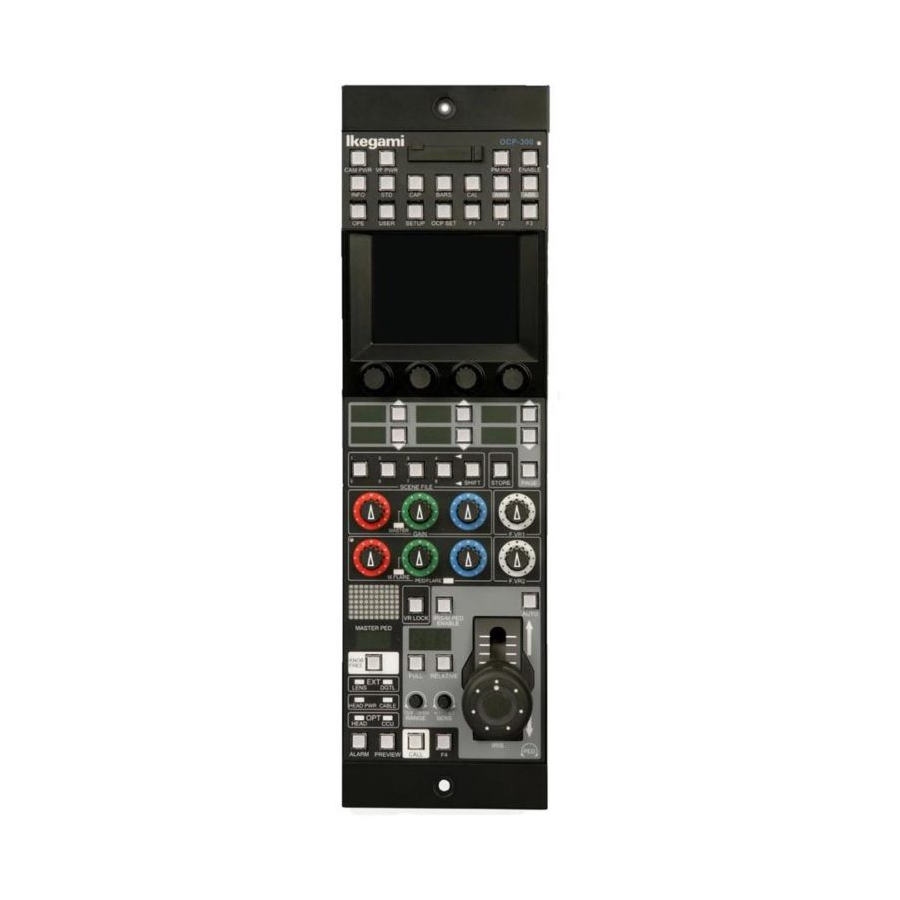
2. The Name and Function of Each Part 2-1 2. The Name and Function of Each Part Since OCP-300 has many functions, it will be divided and explained according to the blocks. VR TYPE 1. Camera Function Control Unit 2. LCD Menu-Operations Part 3. -
Page 22: Camera Function Control Unit
2-2 2. The Name and Function of Each Part 2.1 Camera Function Control Unit CAM PWR switch Remote control can perform power transmission from BS/CCU to the camera head by OCP. Push the switch, when the power transmission is turned ON from the power transmission status of OFF (the switch goes out). - Page 23 2. The Name and Function of Each Part 2-3 Memory card slot It is a slot for the memory card (SD card) which performs save and call of the camera head and the data of BS/CCU. When you use the memory card, please insert the card into the slot calmly until it will be locked and not returned.
- Page 24 2-4 2. The Name and Function of Each Part MODE switch CAP switch Sets the optical filter in the CAP position and makes the iris of the lens closed. BARS switch Makes the video output signals the color bar signals. CAL switch Inputs 100% or 200% of the CAL signal into the graphic processing of the camera head.
-
Page 25: Lcd Menu-Operations Part
2. The Name and Function of Each Part 2-5 2.2 LCD Menu-Operations Part FUNCTION switch It is a function selection switch of the LCD menu. INFO switch Displays information, such as the camera head and the ON/OFF setting state of BS/CCU on the LCD. - Page 26 2-6 2. The Name and Function of Each Part USER switch Displays the selection switch which the user has set on the LCD. By registering the switch in advance, it can be called with this switch. STD switch Returns the camera head and the data of BS/CCU to the standard setup. If the switch is pushed, the LCD menu will be displayed and it will be operated by the touch panel.
-
Page 27: Selection Function Control Unit
2. The Name and Function of Each Part 2-7 2.3 Selection Function Control Unit SELECT switch, PAGE switch Selects each mode with the switch. Change of ND filter position Change of CC filter position Gain Change of Step GAIN of the camera head Usually, set it to "0 dB."... - Page 28 Caution read-out until the control knob is moved to the center position. Since OCP-300 differs in the disposal method of the control knob, it does not commit the function. After the scene file read-out, please use the knob free function in returning the control knob to the center.
-
Page 29: Control Knob Part
2. The Name and Function of Each Part 2-9 2.4 Control Knob Part JOYSTICK TYPE VR TYPE FLARE CONT VR LOCK FLARE CONT Control knob R/G/B GAIN control knob Controls the gain of Red, Green and Blue channels. The Green gain serves as operation replaced with R and B. The control knob of the Green gain is controllable also as the master gain. - Page 30 2-10 2. The Name and Function of Each Part R/G/B PED/FLARE control knob Controls the pedestal or the flare of the Red, Green and Blue channels. The FLARE CONT switch (VR TYPE) or VR LOCK switch (JOY/RE TYPE) of (3) performs the change of the pedestal and flare.
-
Page 31: Iris/Pedestal Control Section (Vr Type)
2. The Name and Function of Each Part 2-11 2.5 Iris/Pedestal Control Section (VR TYPE) AUTO IRIS switch (VR TYPE) Makes the iris control of the lens in the auto mode. Reference : Please refer to "6.2 Auto Iris Operation" and "7.2 Auto Iris Operation" for detailed operation. - Page 32 2-12 2. The Name and Function of Each Part FULL/RELATIVE switch FULL switch Fixes the range of the IRIS control of clause to the FULL range. RELATIVE switch The iris control of the lens lights up at the time of relative-value control. Moreover, the iris position of the lens can be matched with the IRIS control value of OCP by pushing the switch.
- Page 33 2. The Name and Function of Each Part 2-13 IRIS control knob (VR TYPE) Controls the iris of the lens. Controls ±1 stop with the F value at the time of AUTO IRIS. Reference : Please refer to "6.2 Auto Iris Operation" and "7.2 Auto Iris Operation" for detailed operation.
-
Page 34: Iris/Pedestal Control Section (Joystick Type)
2-14 2. The Name and Function of Each Part 2.6 Iris/Pedestal Control Section (JOYSTICK TYPE) PREVIE Switch IRIS Control M PED Control AUTO IRIS switch (JOYSTICK TYPE) ) Makes the iris control of the lens in the auto mode. Reference: Please refer to "6.2 Auto Iris Operation" and "7.2 Auto Iris Operation"for detailed operation. - Page 35 2. The Name and Function of Each Part 2-15 IRIS indicator (JOYSTICK TYPE) Displays the F value of the lens. After exceeding F16 until CLOSE, it becomes "---" and does not display the F value. FULL/RELATIVE switch (JOYSTICK TYPE) FULL switch Fixes the range of the IRIS control of clause to the FULL range.
- Page 36 2-16 2. The Name and Function of Each Part JOYSTICK JOYSTICK TYPE Controls IRIS and the master pedestal by JOYSTICK. Controls ±1 stop with the F value at the time of AUTO IRIS. Controls the master pedestal by the M-PED control. If the head of JOYSTICK is pressed down, the PREVIEW switch turns "ON".
-
Page 37: Status Display Part
2. The Name and Function of Each Part 2-17 2.7 Status Display Part Camera number indicator Displays the program number of the connected camera. Reference : For details, please refer to "11.3 Program Number." MASTER PED indicator Displays the adjustment value of the master pedestal. KNOB FREE switch While pushing this switch, if "2.4 clause... - Page 38 2-18 2. The Name and Function of Each Part clause M.PED control knob of "2.6 Iris/pedestal control section (JOYSTICK TYPE)", clause IRIS SENSE control knob at the time of relative-value control and clause IRIS control knob are set FREE and the knob is turned, the control can be held. For example, in the case where AWB and AUTO SETUP are performed when the R/G/B GAIN knob is not in the center position, or when ABB or AUTO SETUP are performed when the R/G/BPED and M.PED knobs are not in the center positions and each knob...
- Page 39 2. The Name and Function of Each Part 2-19 OPT indicator Displays the transmission level when using the optical fiber cable. The light level from the camera head to CCU is displayed on the CCU indicator, and the optical transmission level from CCU to the camera head is displayed on the HEAD indicator. Each indicator displays...
-
Page 40: Connector Panel
2-20 2. The Name and Function of Each Part 2.8 Connector Panel The connector for LAN Connects BS/CCU corresponding to Ethernet with a LAN cable. ICCP/ARC NET/Ethernet changeover switch Changes ground command connection, ARC Internet connection and Ethernet connection. ICCP at the time of ground command (serial command) connection ARC NET : at the time of ARC network connection... - Page 41 2. The Name and Function of Each Part 2-21 Reference : Refer to "23.2 The Pin Function of the External Connector" for the pin function. COMMAND connector Connects CP cable.
-
Page 42: About A Network
3- 1 3. Network 3. About a Network There is operation in a network as a big feature of OCP-300. This chapter describes the concept and the setting method of operation by ARC network and Ethernet. 3.1 ARC Network 3.1.1 Network Key Map... -
Page 43: System Configuration Example
3. Network 3-2 3.1.2 System Configuration Example 1) In the case of one studio and two control rooms Studio BSH-200 Equipment room Control room 1 Control room 2 CPH-200 CPH-200... - Page 44 3- 3 3. Network 2) In the case of two studios and two control rooms Studio 1 Studio 2 Equipment room 1 Equipment room 2 BSH-200 BSH-200 Control room 2 Control room 1 CPH-200 CPH-200...
-
Page 45: Setup Of Arc Net Id
"CPH-200/BSH-200 Setup Manual" etc. for the details of network connection. Connection with CPH-200 (CP hub) Connect it by a CP cable between OCP-300 and CPH-200 (CP hub). Please connect CPH-200 to the CP connector and connect the control panel to the COMMAND connector. - Page 46 3- 5 3. Network Example) OCP-300 (JOYSTICK TYPE) CPH-200...
- Page 47 The video signal interlocked with the Preview switch can be obtained by using this signal and controlling the general-purpose routing switcher. Image Image Routing switcher PreVIEW Each Each BS/CCU BS/CCU BSH-300 PreVIEW Command B-Type BSH-300 A-Type/ C-Type CP cable OCP-300...
- Page 48 3- 7 3. Network The Preview signal serves as parallel control of the PREVIEW switch operation by OCP and camera selection operation of MCP. In the operation from OCP, it becomes ON while the PREVIEW switch is pressed, and if the switch is released, it will be set to OFF.
-
Page 49: Ethernet
3. Network 3-8 3.2 Ethernet 3.2.1 Network Key Map Ethernet non-convertible BS/CCU Ethernet convertible BS/CCU BSH-300 B-Type Network Hub BSH-300 BSH-300 C-Type A-Type Ethernet convertible OCP (OCP-300) Ethernet non-convertible MCP/OCP... -
Page 50: Ethernet Connection Method
OCP-300. When connecting OCP-300 and BS/CCU corresponding to Ethernet, connect them with a crossing LAN cable. At this time, for the power supply provision to OCP-300, connect the external power with BS/CCU by a COMMAND cable or connect it from D subconnector. -
Page 51: Lcd Menu
4. LCD Menu 4 -1 4. LCD Menu OCP-300 has realized various functions with the menu and touch panel which are displayed on the LCD. The ON/OFF state confirmation of the camera function and the setup of various functions can be performed on the LCD by the switch and rotary encoder knob which are displayed on the screen. - Page 52 4. LCD Menu INFO switch Displays information, such as the camera head and the ON/OFF established state of BS/CCU on the LCD. OPE switch Lets the LCD menu be in the mode suitable for operation. SETUP switch Displays the item in connection with camera adjustment on the LCD menu. OCP SET switch Displays the setting item of OCP on the LCD menu.
-
Page 53: Info
4. LCD Menu 4 -3 Item Background color Status Switch Yellow Function ON Special status Gray (light) Function OFF Normal operation state Gray (dark) Function None Rotary encoder Yellow Effective (Caution) Gray (light) With no effect : The background color of the rotary encoder part serves as a guide. Caution In an effectless display, operation with the rotary encoder knob may be possible according to the connected camera head, the type of BS/CCU and the function item. - Page 54 4. LCD Menu Page 1 C.Temp 5600K Turn on and off the electric color temperature filter 5600K. Color SAT. Turn on and off the color saturation control. At the time of "ON", turn the rotary encoder knob 1 and control the level. Displays Control Data under an item.
- Page 55 4. LCD Menu 4 -5 Page 2 Gain Red Turn the rotary encoder knob 1 and control the level of R Gain. C.Temp 5600K Turn on and off the electric color temperature filter 5600K. VAR C.Temp Turn on and off the variable color temperature. At the time of "ON", turn the rotary encoder knob 2 and control the variable color temperature.
- Page 56 4. LCD Menu Page 3 Zoom Remote Turn on and off the remote of the zoom control of the lens at the time of serial lens connection. At the time of "ON", turn the rotary encoder knob 1 and control the zoom. Turn on and off the automatic color temperature tailing function.
-
Page 57: Setup
4. LCD Menu 4 -7 4.4 SETUP Press the SETUP switch from the FUNCTION switch on the top of the LCD. A screen as shown in the following figure is displayed on the LCD. The screen serves as 2 page configuration. The switch on the top right of the screen can perform the change of the page. - Page 58 4. LCD Menu The page can be switched as follows by pressing the switch. Pressing any one selection switch of Ped, Black Set, Flare, Gamma, Gain, Flexible Mode and Shutter of Video1 will display the adjustment item on the white bar part. The sub selection switch control data or mode will be displayed on the bottom of it and the related ON/OFF switch on the right.
- Page 59 4. LCD Menu 4 -9 A gray item is adjusted by the rotary encoder knob.
- Page 60 4-10 4. LCD Menu A gray item is adjusted by the rotary encoder knob.
- Page 61 4. LCD Menu 4 -11 A gray item is adjusted by the rotary encoder knob.
- Page 62 4-12 4. LCD Menu A gray item is adjusted by the rotary encoder knob.
- Page 63 4. LCD Menu 4 -13 Detail, D/C Detail (Setup 1/2) The following operation will be possible if it is moved to the Detail or D/C Detail screen. Basic operation is the same as the Video screen. The D/C Detail screen works only when it is connected with the camera head and BS/CCU having a down converter.
- Page 64 4-14 4. LCD Menu A gray item is adjusted by the rotary encoder knob.
- Page 65 4. LCD Menu 4 -15 Color, D/C Color (Setup 1/2) The following operation will be possible if it is moved to Color or D/C Color screen. Basic operation is the same as the Video screen. The D/C Color screen works only when it is connected with the camera head having a down converter and BS/CCU.
- Page 66 4-16 4. LCD Menu...
- Page 67 4. LCD Menu 4 -17 A gray item is adjusted by the rotary encoder knob.
- Page 68 4-18 4. LCD Menu A gray item is adjusted by the rotary encoder knob.
- Page 69 4. LCD Menu 4 -19 System (Setup 1/2) The adjustment item concerning the system is arranged. A gray item is adjusted by the rotary encoder knob.
- Page 70 4-20 4. LCD Menu Lens The adjustment item concerning the lens is arranged. A gray item is adjusted by the rotary encoder knob.
- Page 71 4. LCD Menu 4 -21 Triax The adjustment item concerning Triax is arranged. A gray item is adjusted by the rotary encoder knob.
- Page 72 4-22 4. LCD Menu Others The adjustment item with comparatively low frequency in use is arranged. A gray item is adjusted by the rotary encoder knob.
- Page 73 4. LCD Menu 4 -23 Search Search Window can be displayed when the Search button on the top right of Video 1 - Others is pressed. The name of each selection switch shown on the screen of Video1 - Others can be changed when the rotary encoder 3 is operated in the status where Search Window is open, and if the Enter switch is pressed under the name of the selection switch currently looked for, Search Window closes and switches to the screen on which the...
- Page 74 4-24 4. LCD Menu ON/OFF CTRL (Setup 1/2) If ON/OFF CTRL is pressed, selection of ON/OFF of the function to which the camera head and BS/CCU correspond can be performed. It has 6 page configuration according to the function and item. The switch on the top right of the screen can perform the change of the page.
- Page 75 4. LCD Menu 4 -25 A gray item is adjusted by the rotary encoder knob.
- Page 76 4-26 4. LCD Menu A gray item is adjusted by the rotary encoder knob.
- Page 77 4. LCD Menu 4 -27 A gray item is adjusted by the rotary encoder knob.
- Page 78 4-28 4. LCD Menu 10) Auto Setup (Setup 1/2) Auto setup of the camera (automatic adjustment) can be performed by pressing the Auto Setup switch. Full (Full Auto Setup) All auto setup items are performed and the camera is initialized. Mainly it is performed at the time of maintenance check.
- Page 79 4. LCD Menu 4 -29 When the auto setup is set to NG, the START switch blinks. It can be canceled by pressing again. Moreover, the auto setup can be stopped by pressing it during execution. In addition, Quick Auto Setup can be performed by long pressing of the AWB switch and Auto Black Shade the ABB switch, respectively.
- Page 80 4-30 4. LCD Menu 11) REF. Setup Pressing the REF. Setup switch on the top right of the Auto Setup screen will display the REF.Setup screen. (If the Auto Setup switch on the top right of the REF.Setup screen is pressed, it will return to the Auto Setup screen) Creates and updates the reference file which is a convergence value of the auto setup of the camera.
- Page 81 If the camera which does not correspond to the video image format change function from OCP-300 and BS/CCU are connected and the Format button of the Setup screen is pressed, an error sound sounds and it cannot move to the System Format screen.
- Page 82 4-32 4. LCD Menu The selection switches are buttons which can set up [BASE FREQ], [IMAGE SIZE], [FIELD FREQ], [SUB SAMPLING] and [SAMPLING BIT] from the left. If Window is displayed, the button on which the selectable setup of the connected device is indicated is displayed.
- Page 83 4. LCD Menu 4 -33 13) WFM/PM (Setup 1/2) If WFM/PM is pressed, the signal of the camera head, the WFM (Waveform Monitor) output of BS/CCU and PM output can be selected. "R", "G", "B", "Y", "ENC" and "-G" can be outputted to the WFM output and PM output (however, there are also devices which do not correspond to -G).
- Page 84 4-34 4. LCD Menu 14) Menu (Setup 1/2) The main menu will be displayed if long pressing of the Menu switch is done. At the time of BS/CCU connection, the menu operations for the function settings of BS/CCU can be performed. The menu operation of the camera head can be performed at the time of camera head connection.
- Page 85 If it moves to the MEM.Card Save/Load screen, SAVE/LOAD of the various files concerning the connected camera and BS/CCU will be performed to the SD card inserted in the card slot of OCP-300. 16) Name Entry (Setup 2/2) Scene File If the Name Entry switch is pressed, it moves to the SceneFile Name screen and the name can be registered into each scene file.
- Page 86 4-36 4. LCD Menu Camera ID If the Camera ID switch on the top right of the SceneFile Name screen is pressed, it will move to the Camera ID screen. (If the SceneFile Name switch on the top right of the Camera ID screen is pressed, it will move to the SceneFile Name screen) Camera ID can be registered on this screen.
-
Page 87: Ocp Setup
A screen as shown in the following figure will be displayed on the LCD. Control Depth OCP-300 can set up the operation range. The setting range is protected by a password. Reference : For details, please refer to a "12.1. Operation Delimitation Function."... - Page 88 For details, please refer to "11 Setup of Panel Assignment and the Program number." Panel Config OCP-300 can carry out setting and changing the specification according to the system to be used and user-friendliness. Reference : For details, please refer to "21 Panel config (Setup of the Panel)."...
- Page 89 4. LCD Menu 4 -39 User Preset Perform a setup when FUNCTION switch USER on the top of the LCD is pressed. Reference : For details, please refer to "15 USER Menu." OPE Preset Performs a setup when the FUNCTION switch OPE on the top of the LCD is pressed. Reference : For details, please refer to "16 OPERATION Screen Setting."...
- Page 90 4-40 4. LCD Menu Memory Card Panel data can be saved on an SD memory card, and it can be read if needed. It comes to simplify not only saving as backup data but copying the data created by one set to other OCPs or to be able to have different data for a program and video engineer.
- Page 91 For details, please refer to "17.2 Saving Method of the Setting in the Main Part of the Control Panel." 4.6 VR Data OCP-300 displays the contents of the FUNCTION switch currently assigned, and the status of main part volume when no LCD are selected. The clearing of the volume value...
- Page 92 4-42 4. LCD Menu Reference : Please refer to "21.2.3 FUNCTION VR" for the function assignment of F.VR1 and F.VR2. If Window is displayed, the variable range of the corresponding volume can be changed by pressing each switch. Variable range which can be set up by VR Range Setting Selections Functional description...
-
Page 93: Operation Of The Control Knob
5. Operation of the Control Knob 5-1 5. Operation of the Control Knob 5.1 Camera Data Adjustment There are generally two types of data control of the camera, which are the absolute control and the relative control. (There are data control of the camera head and BS/CCU; however, we will use the term "camera"... - Page 94 5-2 5. Operation of the Control Knob Turning clockwise provides the positive data, and turning counterclockwise provides the negative data (relative). The sent data (relative data) is added to the camera manual file. When operating the rotary encoder knob, the amount of sending data varies according to the turning speed.
- Page 95 5. Operation of the Control Knob 5-3 3) Camera Data Processing The camera calculates the volume file and the manual file according to the sent relative data and absolute data respectively. The camera controls the data by using the target file, of which the volume file, manual file, and other files are added.
- Page 96 5-4 5. Operation of the Control Knob Advantage Disadvantage Application Absolute The control amount is Only one control device Suited for control determined according to can be connected to operations. the turned angle of the one camera. Not suited control knob. Therefore, it for fine adjustments.
-
Page 97: Control Method With Ocp-300
While operating the control knob, the potentiometer value is converted from analog to digital at a certain interval. At this time, OCP-300 does not transfer the data as an absolute value. Rather, it compares the A/D conversion value with the former A/D conversion value and transfers the difference of the values as an relative data. -
Page 98: Reconnection Process
Reconnection Control knob With OCP-300, the operation amount of the control knob is sent as the relative data. Therefore, jumping of the camera data does not occur even when the control knob positions are different between before and after the reconnection. - Page 99 5. Operation of the Control Knob 5-7 With this function, you can switch the connection of the control panel or assign the setting without worrying about the control knob positions. Thus, an adjustment after the connection becomes unnecessary. (However, the iris may move depending on the setting.) In addition, this function is valid for reading of scene files.
-
Page 100: Knob Free Function
5-8 5. Operation of the Control Knob 5.4 Knob Free Function OCP-300 has the knob free function. With this function, the control knob operation becomes invalid while the knob free switch is being pressed. Therefore, this function is useful for preventing the control knob to be effective on only one side or for expanding the operation range of the control knob. - Page 101 5. Operation of the Control Knob 5-9 Offset Clear Manual file Reconnection Control Knob Knob free...
- Page 102 5-10 5. Operation of the Control Knob 2) Knob Free Item VR TYPE JOYSTICK TYPE Items that the knob free function is effective Items that the knob free function is effective are as follows. • R/G/B GAIN • R/G/B PED •...
- Page 103 5. Operation of the Control Knob 5-11 3) Knob Free Lock Function (VR TYPE only) The VR TYPE has the knob free lock function. With the standard knob free function, the control knob becomes invalid while the knob free switch is being pressed. On the contrary, with the knob free lock function, the control knob becomes invalid even when the knob free switch is released.
-
Page 104: Absolute Iris Control
OCP. During the absolute value iris control, the RELATIVE switch lights off. This control method is adopted for the initial setting of the Ikegami command. You can switch between "absolute value iris control" and "relative value iris control" by using the panel configuration. -
Page 105: Clearing The Iris Manual File
MCP and the BS/CCU of OCP is connected in parallel. In case of OCP-300, there are cases that the manual files are not automatically cleared depending on the network connection and the control panel concurrently connected. -
Page 106: Relative Iris Control
7-1 7. Relative Value Iris Control 7. Relative Value Iris Control With the relative value iris control, the iris is controlled by the relative data as the control of the MCP. During the relative value iris control, the RELATIVE switch lights on. - Page 107 When the lens iris position and the OCP IRIS control value become different, the OCP-300 can indicate that condition with the RELATIVE switch blinking, depending on the camera head firmware version. In this case, you can match the OCP IRIS control value and the lens iris position by pressing the RELATIVE switch.
-
Page 108: Auto Iris Operation
7-3 7. Relative Value Iris Control 7.2 Auto Iris Operation During the auto iris operation, fine adjustment of approximately ± 1 stop for the F value for auto iris control value is possible by using the IRIS control knob regardless of the FULL switch condition. -
Page 109: Initial Mode
7. Relative Value Iris Control 7-4 After switching, you can start the operation from the IRIS control knob position at that time. When the FULL switch is on, the IRIS variable range setting knob becomes invalid. When the FULL switch is off, the IRIS variable range setting knob becomes valid. -
Page 110: Manual Setting/Manual Clearing
8-1 8. Manual Setting/Manual Clearing 8. Manual Setting/Manual Clearing You can teach the values, which are adjusted by the OCP rotary encoder knob and the control knob (manual setting). In addition, you can also return to those taught values (manual clearing). 8.1 Manual Setting/Manual Clearing on the LCD Screen On the screen, where adjustment with the rotary encoder knob is available, press the control data section of the item, of which you conduct the manual setting or manual... - Page 111 8. Manual Setting/Manual Clearing 8-2 The control data indication section turns to red, and the manual set/clear screen opens over the original screen. Press the control data section of the item, of which you want to add the manual setting or manual clearing. The color turns to red, which indicates that the item is properly selected.
-
Page 112: Indication Of The Control Data Offset
8-3 8. Manual Setting/Manual Clearing 8.2 Indication of the Control Data Offset When the [Offset] switch on the MAN. SET/CLR screen is turned to "ON" (amber), the control data indication value becomes the deviation from the value registered by the manual setting (or the value automatically adjusted by the automatic setup) (offset indication mode). - Page 113 8. Manual Setting/Manual Clearing 8-4 Push figures Red indication White indication Amber Red indication Red indication In addition, the offset indication mode ON/OFF status set on this setting screen is also valid on the screens without indication of the setting screen. At that time, the control data indication is blue when the offset indication mode is on.
-
Page 114: Manual Bulk Clearing By The Control Knob Operation
8-5 8. Manual Setting/Manual Clearing 8.3 Manual Bulk Clearing by the Control Knob Operation Manual bulk clearing is available for all items of the control knob. When nothing is selected on the LCD screen indication, the VR Data screen opens on the LCD screen. - Page 115 8. Manual Setting/Manual Clearing 8-6 The data to be cleared are the items of the control knob. However, the data Caution operated with the rotary encoder knob are also cleared. For example, if the R GAIN item is operated both with the control knob and the rotary encoder knob, the data for the control knob operation and the data for the rotary encoder operation are both cleared.
-
Page 116: All Manual Setting/All Manual Clearing
8-7 8. Manual Setting/Manual Clearing 8.4 All Manual Setting/All Manual Clearing Manual setting and manual clearing are available for all operation items of the camera head and the BS/CCU. 1. Press the [STD] switch from the FUNCTION switches on the top of LCD screen. 2. - Page 117 8. Manual Setting/Manual Clearing 8-8 In this operation, the bulk manual setting and clearing are possible even Caution when the function is off. There are items that manual setting and clearing are not available depending on the camera head and the BS/CCU specifications.
-
Page 118: How To Use The Memory Card
The upper limit of the usable SD memory card capacity also differs depending on the updating program version that is used for updating the firmware. The upper limit of the capacity for OCP-300 is 32 G byte of the SDHC memory card. Note : The mini SD cards and micro SD cards with application of the adapter are out of operation warranty range. -
Page 119: Inserting And Removing The Memory Card
9. How to Use the Memory Card 9-2 9.2 Inserting and Removing the Memory Card When using the memory card, raise the left side of the slot cover and turn clockwise. Carefully insert the memory card to the memory card slot with the correct direction (terminal side facing the back side with a n at the lower left side) until a clicking sound is made. -
Page 120: Creating The Memory Card Name And File Name
9-3 9. How to Use the Memory Card 9.3 Creating the Memory Card Name and File Name You can name a file to be saved in the memory card. Up to 11 characters can be used for the extension of the memory card, and up to 8 and 3 characters can be used for the extension of the file. -
Page 121: Saving The File Data To The Memory Card
9. How to Use the Memory Card 9-4 9.4 Saving the File Data to the Memory Card 1. Insert the memory card to the memory card slot with the correct direction (terminal side facing the back side with a notch at the lower left side). 2. - Page 122 9-5 9. How to Use the Memory Card 5. Turn on the [Save] switch. Extension Any name can be used for the extension. When no name is selected, the name becomes as follows according to the file type. File name “ALL”...
- Page 123 9. How to Use the Memory Card 9-6 When saving the data, check the clock on the information screen. Caution The checked time is used as the time stamp on the SD card.
-
Page 124: Invoking The File Data From The Memory Card
9-7 9. How to Use the Memory Card 9.5 Invoking the File Data from the Memory Card 1. Insert the memory card to the memory card slot. 2. Press the [SETUP] switch from the FUNCTION switches on the top of the LCD screen. - Page 125 9. How to Use the Memory Card 9-8 Note : Pressing the file data name on the LCD screen displays the file data information. You can check the model name of the camera and the file type. In addition, turning the file search control knob in this condition displays the information of the file data in the card continuously.
- Page 126 9-9 9. How to Use the Memory Card Note : When the file data type is different, there are cases that invoking is not possible. For example, if you try to invoke the file data, which is saved as the LENS DATA, as the SNAP SHOT data, the following warning appears.
-
Page 127: Deleting The File Data From The Memory Card
9. How to Use the Memory Card 9-10 9.6 Deleting the File Data from the Memory Card When deleting the file data that are saved in the memory card, take the following procedure. You cannot restore the deleted file data. Therefore, pay utmost care when deleting the file data. -
Page 128: Updating The Firmware By Using A Memory Card
Be careful that the file data is deleted even the file data type is different. Caution 9.7 Updating the Firmware by Using a Memory Card You can upgrade the version of OCP-300, connected camera, and BS/CCU firmware by using a memory card. Reference : Refer to "24. Updating the Firmware" for details. -
Page 129: Indicating The Message Of Each Type
9. How to Use the Memory Card 9-12 9.8 Indicating the Message of Each Type There are cases that some messages open while saving, invoking, or deleting the data by using a memory card. The contents are as follows. In case of [ERROR] indication, pressing "OK" cancels the indication. Message Explanation [ WARNING ]... - Page 130 9-13 9. How to Use the Memory Card Message Explanation [ ERROR ] This message appears when a user cannot invoke the data because the file data type in the memory card is different. This message appears when a user tries to invoke the data when there is no file data in the memory card.
- Page 131 9. How to Use the Memory Card 9-14 Message Explanation [ ERROR ] This message appears when a user tries to invoke the data in the memory card but there is no formal data. This message appears when a user tries to invoke the data in the memory card but the file data in the memory card are broken.
- Page 132 9-15 9. How to Use the Memory Card Message Explanation [ ERROR ] This message appears when an abnormal condition occurs during the file data processing in the camera system. • “COMMAND TROUBLE” : When there is a trouble in the communication processing system •...
-
Page 133: Information
10. Information 10-1 10. Information There is an information function that displays the list of statuses such as ON/OFF setting status of camera head and BS/CCU and the status of this control panel on the LCD screen. To load the information screen, press INFO switch from the FUNCTION switches on the top of the LCD screen. - Page 134 10-2 10. Information The Camera Status display screen does not include all camera functions. Caution Some items are not displayed if their switches are in the camera function operating section on the top of the LCD screen are not displayed. For example, BARS ON/OFF, etc.
- Page 135 10. Information 10-3 Camera Status (3/3) List of standard settings Initial standard Initial standard Item Item settings settings Filter CONT Step Gain Digital EXT Zoom Remote Focus Remote AWB Memory Filter Hold AWB CH Night Mode Note : The content of standard setting is the same as the content that is set in Clear to Standard of the standard function.
- Page 136 10-4 10. Information Diagnostic Press [Camera Status] switch on the LCD screen to open the Camera Status screen. This display allows a simple diagnosis even in the system that cannot connect the PM to the BS/CCU output. The diagnosis may not be displayed (" " is displayed) on this screen for Caution BS/CCU even when the diagnosis is displayed on the PM.
- Page 137 10. Information 10-5 OK is displayed in green, ATT (Attention) in yellow, and WARN (Warning) and NG in red. When the OPT level status gets lower than ATT, the display of OPT level status on the first page of Diagnostic will be inverted.
- Page 138 Press [Firmware] switch to open the Firmware screen. It can display the program number of firmware for both OCP-300 and the connected devices. The each version of FPGA for this OCP-300 is also displayed on the second page. This would be displayed only for the devices that support command.
- Page 139 10. Information 10-7 OCP Setting Press [OCP Setting] switch on the LCD screen to open the OCP Setting screen. When the OCP Setting screen is opened, the information on each setting for this control panel will be displayed. The OCP Setting display screen is shown on the page 10.
- Page 140 10-8 10. Information Reference : Please refer to "21.3 Control Depth" for the detailed information on the Control Depth. STD Function It is displayed on the pages 9/10 and 10/10. It shows the standard setting displayed on the Camera Status screen of Information. Reference : Please refer to "21.4 STD FUNCTION"...
-
Page 141: Direct Jump Function
10. Information 10-9 Reference : Please refer to "11. Setting the Panel Assignment and Program Number" for the detailed information on Assign. Key Data It is displayed on the pages 3/3. It shows the ON/OFF status for the optional functions of this control panel. 10.2 Direct Jump Function There is a direct jump function on the Camera Status display screen. - Page 142 10-10 10. Information The left side of Camera Status (1/3) is corresponding to the ON/OFFCTRL (1/6) screen. The right side of Camera Status (1/3) is corresponding to the ON/OFFCTRL (2/6) screen. The left side of Camera Status (2/3) is corresponding to the ON/OFFCTRL (3/6) screen. The right side of Camera Status (2/3) is corresponding to the ON/OFFCTRL (4/6) screen.
-
Page 143: Setting The Panel Assignment And Program Number
The command connection between the BS/CCU and control panel can be changed with ARC ID for the ARC network connection. Set the ICCP/ARC/ETHER selector switch on the top of the COMMAND cable connector of OCP-300 to ARC. Communication setting Press OCP Set from FUNCTION switches on the top of LCD screen. - Page 144 Press [Assign] switch from the LCD screen. Press [OCP-300] switch from the LCD screen. ARC ID of this control panel can be set in [OCP-300] screen. If you press [ARC ID(HEX)] switch in the LCD screen and operate the rotary encoder 4, you can operate the displayed ARC network ID.
- Page 145 11. Setting the Panel Assignment and Program Number 11-3 Press switch on the top of LCD screen to return to the Assign screen, and then press [BS/CCU] switch. Enter the ARC ID (HEX) of BS/CCU that has been connected through the same operation as 5.
-
Page 146: Setting The Ip Address/Subnet Mask/Default Gateway
11.2 Setting the IP Address/Subnet Mask/Default Gateway Set the ICCP/ARC/ETHER selector switch on the top of the COMMAND cable connector of OCP-300 to ETHER. Press OCP Set from FUNCTION switches on the top of LCD screen. Press [Assign] switch from the LCD screen. - Page 147 IP Address, Subnet Mask, Default Gateway ARC ID of this control panel can be set in [OCP-300] screen. If you press the item you want to set for [IP Address], [Subnet Mask], and [Default Gateway] switches and operate the rotary encoders 1 to 4, you can operate each value of displayed addresses.
- Page 148 11-6 11. Setting the Panel Assignment and Program Number Enter the IP Address of BS/CCU that has been connected through the same operation as 5. If the IP Addresses of the control panel and BS/CCU on the network of the camera system are not duplicated, they can be connected normally.
-
Page 149: Program Number
11. Setting the Panel Assignment and Program Number 11-7 11.3 Program Number You can set the program number, which is also the camera number for program operation and maintenance. The program number you have set is displayed in the camera number indicator and also sent to the camera head with a command. -
Page 150: Program Number For Changing The Panel Assignment
11-8 11. Setting the Panel Assignment and Program Number 11.4 Program Number for Changing the Panel Assignment When you change the panel assignment and the connection of triax cable or fiber cable between the BS/CCU and camera head, the program number is obtained from the camera head, and the program number of OCP is changed to the number of the camera head. -
Page 151: Display Mode Of Program Number
11. Setting the Panel Assignment and Program Number 11-9 11.5 Display Mode of Program Number If the control panel is connected to the camera head without program number function (the number is stored even when the display function is not available), the program number will be retained because it cannot be obtained from the camera head. - Page 152 11-10 11. Setting the Panel Assignment and Program Number In the SELF mode, if the Assign setting is changed, the program number of the camera number indicator in the control panel will be changed to the stored number, and the program number will be sent to the camera head by a command.
- Page 153 11. Setting the Panel Assignment and Program Number 11-11 CAM mode (CAMERA has priority) The number stored in the camera head has priority for the program number display. The display of camera number indicator of OCP is changed based on the answer from the camera head when the power is turned on or the assignment is set, etc.
-
Page 154: Setting The Program Number Function For Bs/Ccu
11-12 11. Setting the Panel Assignment and Program Number 11.6. Setting the program number function for BS/CCU Some BS/CCUs have a program number function. The program number function can be enabled with the menu setting of BS/CCU. If the OCP is connected to the BS/CCU in which the program number function is enabled, the number stored in the BS/CCU has priority for the program number display. - Page 155 11. Setting the Panel Assignment and Program Number 11-13 Note : If you want to use the program number together with the input of system switcher, set the program number function of BS/CCU to be enabled. When the program number of BS/CCU is enabled, make sure to set the Caution display mode of OCP to the CAM mode.
-
Page 156: Availability Of Display Mode And Program Number Function
11-14 11. Setting the Panel Assignment and Program Number 11.7. Availability of Display Mode and Program Number Function Operation is different in the camera with program number function and the camera head without the function. You need to decide which mode (either CAM mode or SELF mode) should be used based on the frequency of the control panel assignment or whether the camera connection is changed or not. - Page 157 11. Setting the Panel Assignment and Program Number 11-15 Note : In general, we recommend that you set to CAM if the system consists of only the camera with program number function, and to SELF if the system includes a camera without the program number function The program number function is used to store the program number.
-
Page 158: Operation Range Setting Function
12-1 12. Operation Range Setting Function 12. Operation Range Setting Function 12.1 Function Overview The operation range of OCP-300 can be set to four levels as shown below. The setting range is protected by a password. Basic Operation of the LCD related to operation is prohibited. - Page 159 12. Operation Range Setting Function 12-2 3. [Complete] switch is selected as the factory default setting, and there is no restriction on the operation. Press to return to the OCP SET screen. 4. Press [Basic], [Standard], [Extended], or [Complete] switch to change the operation range.
- Page 160 12-3 12. Operation Range Setting Function...
-
Page 161: How To Change The Password
12. Operation Range Setting Function 12-4 12.3 How to Change the Password If [Change PASSWORD] switch in the CONTROL DEPTH screen is pressed, the following screen will be displayed. Enter the old 4-digit password ([0] [0] [0] [0] for the factory default setting). Once the password is confirmed, you can enter a new password. -
Page 162: Detailed Information On The Initial Operation Range
12-5 12. Operation Range Setting Function 12.4 Detailed Information on the Initial Operation Range... - Page 163 12. Operation Range Setting Function 12-6...
- Page 164 12-7 12. Operation Range Setting Function Basic * From INFORMATION * From INFORMATION Transfer to MODE SWITCH is Transfer to MODE SWITCH is prohibited. * Saving SCENE FILE is prohibited. Standard * From INFORMATION * From INFORMATION Transfer to MODE Transfer to MODE SWITCH is SWITCH is prohibited.
-
Page 165: Changing The Operation Range
12. Operation Range Setting Function 12-8 Extended Complete There is no restriction on the operation. 12.5 Changing the Operation Range Each item of the operation range can be arbitrarily changed. Reference : Please refer to "21.3 Control Depth" for changing the operation range. -
Page 166: Standard Function
Clear to Standard can reset the camera to the standard setting by sending an individual command from OCP-300. Therefore, the items that can be reset to the standard setting are the items that can be operated by a normal panel operation. - Page 167 13. Standard Function 13-2...
- Page 168 13-3 13. Standard Function...
- Page 169 13. Standard Function 13-4 2) Recall Preset File Recall Preset File can read Preset File that is saved in the backup memory in advance, by sending a special command from the control panel. Some Preset File may contain factory data and user data depending on the specifications of camera head and BS/CCU.
-
Page 170: Operation Procedure
13-5 13. Standard Function 13.2 Operation Procedure 1. Press STD switch on the camera function operation panel at the top of the LCD screen. 2. As the following operation screen is displayed on the LCD screen, you can select two functions for each Clear to Standard and Recall Preset File. - Page 171 13. Standard Function 13-6 2. If [Execute] switch is pressed, a pop-up screen will appear on the LCD screen to call your attention. If “No” is selected, it will return to the previous screen without execution. 3. If “Yes” is selected, the execution will be started. 4.
- Page 172 13-7 13. Standard Function If the item is selected, [Engineer] and [Factory] switches will appear on the bottom of the screen. There you can select whether to load the engineering data or to load the factory data. If either of switches is pressed, [Execute] switch will be displayed on the bottom of the LCD screen.
- Page 173 13. Standard Function 13-8 If an error occurs while loading data, a pop-up screen will appear. Once you confirmed, press "OK". After loading Preset File, the camera head and BS/CCU may be reset to Caution enable state restoration. If the camera head and BS/CCU are reset, OCP may be temporarily disabled or the LCD screen may disappear.
-
Page 174: Character Setting
14-1 14. Character Setting 14. Character Setting 1. Press [OCP SET] switch from FUNCTION switches on the top of LCD screen and press Setup switch. 2. The menu (including BARS TITLE) of the camera can be set by pressing and holding the [Menu] switch. -
Page 175: Setting The Camera Menu
14. Character Setting 14-2 14.1 Setting the Camera Menu OCP-300 1. Press and hold Menu switch. Main menu will be displayed. When the BS/CCU is connected, the menu operation can be performed for the function setting of BS/CCU. When the camera head is connected, the menu operation can be performed for the camera head. -
Page 176: Setting The Bars Title
"14.1 Setting the Camera Menu". 1) How to switch ON/OFF the character display of BARS TITLE 1. Select BARS TITLE from the main menu, and display the BARS BARS TITLE OCP-300 BARS TITLE TITLEENTRY screen on the PM. ENTRY BARS TITLE ENTRY screen 2. - Page 177 14. Character Setting 14-4 2) How to edit the characters of BARS TITLE OCP-300 Select BARS TITLE from the main BARS TITLE menu, and display the BARS TITLE BARS TITLE ENTRY screen on the PM. ENTRY BARS TITLE ENTRY screen Select TITLE EDIT”...
- Page 178 14-5 14. Character Setting 3) Setting the display position of BARS TITLE characters Select BARS TITLE from the main BARS TITLE OCP-300 menu, and display the BARS TITLE BARS TITLE ENTRY screen on the PM. ENTRY BARS TITLE ENTRY screen...
-
Page 179: Setting The Scene File Name
14. Character Setting 14-6 14.3 Setting the Scene File Name You can register a name for each scene file. Since the registered name can be always displayed on the PM, you can check what kind of scene is set for each scene file. Up to 31 characters (alphanumerical and special characters) can be registered for a name. - Page 180 14-7 14. Character Setting 3. The registered name of Scene File Name will be displayed. 1. Cursor knob : Move the cursor left and right to select a character. 2. Character type select knob : Used to input the small alphabet for [abc], large alphabet for [ABC], number for [012], and symbols for [#%&].
-
Page 181: Setting The Camera Id
14. Character Setting 14-8 5. Press PM IND/PAGE switch several times. The screen of PM is changed to the scene file name display screen, and the scene file name that you have just input will be displayed on the screen. Scene file name registration screen Scene file name for the registered scene... - Page 182 14-9 14. Character Setting 3. When the Scene File Name screen is displayed, press [Camera ID] switch on the top right corner of the screen.
- Page 183 14. Character Setting 14-10 4. The screen to register the Camera ID will be displayed. Cursor knob : Move the cursor left and right to select a character. Character type select knob : Used to input the small alphabet for [abc], large alphabet for [ABC], number for [012], and symbols for [#%&].
- Page 184 14-11 14. Character Setting Camera ID display screen Registered Camera ID Perform Step 3 to 4 to re-register. Note : If it is not connected to the camera and BS/CCU that support the Camera ID function, it cannot display and register. If the Camera ID and scene file name are set at the same time in multiple control panels, a malfunction may occur.
-
Page 185: User Menu
15. USER Menu 15-1 15. USER Menu OCP-300 can arbitrarily assign the selection switches on the Setup screen to the USER menu. The USER menu can be switched between 5 pages, and up to 8 selection switches can be assigned per 1 page. - Page 186 15-2 15. USER Menu The pages you want to assign can be switched between [USER 1], [USER 2], [USER 3], [USER 4], and [USER 5] with the on the top of LCD screen. If the switch of the item that you want to assign is pressed, the window for the selection switch will appear.
- Page 187 15. USER Menu 15-3 List of assignable functions Group name Selection switch display Black Set Flare Video1 Gamma Gain CSTM Gamma Shutter Black Shade White Shade Video2 White Clip Knee Soft Detail1 Skin Color Hi-Light D/C DTL D/C Soft D/C Detail D/C Skin D/C Color...
- Page 188 15-4 15. USER Menu List of assignable functions Group name Selection switch display Matrix Color SAT. CSTM Color1 Color CSTM Color2 Color CORR Color Temp Color Hue D/C Matrix D/C Color D/C C.SAT. Auto Iris Lens Zoom Focus DGTL.EXT. Others MIC Gain Auto Setup Default...
-
Page 189: User Menu Search
15. USER Menu 15-5 The selection switch that is set in [User Preset] will be arranged in the User menu. If a switch is pressed, the ON/OFF button and adjustment item for the switch will be displayed on the bottom of the LCD screen. The pages of the USER menu with the on the top of LCD screen can be switched. -
Page 190: Operation Screen Setting
16-1 16. OPERATION Screen Setting 16. OPERATION Screen Setting In the OCP-300, you can arbitrarily add and edit (delete, etc.) the items on the Operation screen. You can assign 8 ON/OFF switches and 4 analog items per 1 page and create up to 5 pages on the Operation screen. - Page 191 16. OPERATION Screen Setting 16-2 If the ON/OFF switch of the item that you want to assign is pressed, the window for the selection switch will appear. Then, turn the rotary encoder 4 times to switch the pages. If the [Close] switch is pressed, the Window will be closed. List of assignable functions Group name Selection switch display...
- Page 192 16-3 16. OPERATION Screen Setting Color Hue ZOOM Remote Focus Remote VAR C.Temp ON/OFF (4/5) Filter HOLD Chrome CSTM Color1 ON/OFF (5/5) CSTM Color2 CSTM CORR If the ON/OFF switch that you want to assign is pressed in the Window for the selection switch, the Window will be closed, and the name of the switch will be changed to that of the assigned selection switch.
- Page 193 16. OPERATION Screen Setting 16-4 List of assignable functions Group name Selection switch display Empty (no display) Color SAT. Color Hue Skin DTL RE (1/4) Z.Skin DTL Z.Track DTL Color DTL Hi-Light DTL PRST Shutter Black STR/PRS Gain Red RE (2/4) Gain Blue Gain Maste VAR C.Temp...
- Page 194 16-5 16. OPERATION Screen Setting The selection switch and analog items that are set in [OPE Preset] will be arranged on the Operation menu. If there is nothing set in a page, that page will not be able to display. The C.Temp5600K will be changed to MATRIX OFF.
-
Page 195: Setting Procedure Of Control Panel
17. Setting Procedure of Control Panel 17-1 17. Setting Procedure of Control Panel OCP-300 can save or load the settings of this control panel in or from a memory card or control panel itself as necessary. In case of a memory card, it can easily save backup data, copy the data that is created with one device to another OCP, and have different data for each program or video engineer. - Page 196 17-2 17. Setting Procedure of Control Panel Standard Data Data for the panel configuration [STD FUNCTION]. RAM Data All data that is saved in the control panel. Key Data Optional function enabled data. It is read-only. As with camera data, individual data can be loaded from the data saved in ALL Data. For example, only the data for User screen setting can be loaded from the data that is saved in ALL Data.
-
Page 197: Setting Procedure At The Control Panel
17. Setting Procedure of Control Panel 17-3 17.2 Setting Procedure at the Control Panel 1. To use a memory card for saving or loading data, press the OCP SET switch from the FUNCTION switches on the top of the LCD screen, and then press the [Preset File] switch in the item selection switch section. - Page 198 17-4 17. Setting Procedure of Control Panel 3. When saving the User File, set the [User File] switch to ON and press the [Save] switch that is displayed on the bottom of the LCD screen. 4. If the [Execute] switch displayed on the bottom right of the LCD screen is pressed, the confirmation window will appear.
- Page 199 17. Setting Procedure of Control Panel 17-5 6. If the [Execute] switch displayed on the bottom right of the LCD screen is pressed, the confirmation window will appear. Then, press [Yes] to load the User File and restart the control panel. If [NO] is pressed, the Window will disappear. 7.
-
Page 200: Iris Position Adjustment Function
OPEN/CLOSE end with full range. OCP-300 has a function that makes the OPEN/CLOSE end position of lens iris recognized and fills the difference with the lens iris value of the camera head by operating the LCD screen. - Page 201 18. IRIS position adjustment function 18-2 2. Set the IRIS position of the control panel to OPEN end. 3. Press [Data Set] switch on the Initial Setup screen. If the switch is pressed, the status of Open Position will be changed to [OK]. 4.
- Page 202 18-3 18. IRIS position adjustment function 6. If both statuses of Open Position and Close Position are changed from [-] to [OK], [All Data Set] switch on the top right corner of LCD screen will flash. If [All Data Set] switch is pressed, the confirmation screen will appear.
-
Page 203: Parallel Connection
19. Parallel Connection 19-1 19. Parallel Connection OCP-300 uses Relative control for operation of the control knob. Control of iris can be selected from either absolute control or increment control in accordance with control configuration. Traditional OCP (RE Type, Joystick Type) was not capable of parallel connection (parallel operation) in which multiple OCPs can be connected simultaneously due to absolute control. -
Page 204: Warning For Arc Network
19-2 19. Parallel Connection 19.2 Warning for ARC Network You can connect the multiple OCPs to the BS/CCU for ARC network. Connecting the OCP to the BS/CCU which is operated under other OCP nay cause trouble when it is operated. Connecting the BS/CCU to the OCP to which any other BS/CCU has been connected may cause warning on LCD screen to confirm the connection, depending on setting of configuration. -
Page 205: Optional Function
20. Option function 20-1 20. Optional Function Paid optional functions are available for the OCP-300. The optional functions are enabled by loading the KEY File. Reference : Please refer to the "17. Setting Procedure of Control Panel" for how to load the KEY File. -
Page 206: Switching Lch/Rch/Operation Control
20-2 20. Option function 2. Set assignment for which camera is to be assigned for Lch camera and Rch camera. Switching over of Lch and Rch to be set is selected by switch on the top right corner of screen Switching Lch or Rch Reference : Please refer to "11. -
Page 207: Function Operation Restriction In Operation Mode
20. Option function 20-3 Select function control section (3D) PAGE LEFT CENTER RIGHT Gain Gamma Bkst 20.1.4 Function Operation Restriction in Operation Mode Operation range setting becomes “Standard” in the operation mode to prevent erroneous operation. Returning to the separate mode resume the setting set at the operation range setting screen. -
Page 208: Status Check Of Lch/Rch Camera
20-4 20. Option function 20.1.5 Status Check of Lch/Rch Camera There may be a case that statuses of Lch/Rch cameras (items that are switched by ON/OFF or STEP) do not match each other immediately after switching to the 3D mode or when mode is switched to the operation mode after adjustment in the separate mode. - Page 209 20. Option function 20-5 Pressing left switches illuminating at the select function control section simultaneously during operation mode enables checking mismatch of statuses of 2 cameras. The following message will be displayed on LCD screen if there is no mismatch. The following message will be displayed on LCD screen if there is any mismatch.
-
Page 210: Operation In Operation Mode
20-6 20. Option function If there is no mismatch, Ikegami standard setting Background [Black], text [White] Other than Ikegami standard setting Background [White], text [Red] Note : Using the function "Clear to Standard" for each Lch/Rch camera is another effective way to eliminate mismatch. -
Page 211: Camera Selection Function And Multi Function
20. Option function 20-7 20.2. Camera Selection Function and Multi Function OCP-300 is equipped with the camera selection function with which you can select a single camera to operate from 10 cameras, and the multi function with which you can select multiple cameras to operate simultaneously. -
Page 212: External Camera Selection
20-8 20. Option function Press the number of camera to be selected from either one of switches 1 through 10 located on [Master] of the window. Assignment of camera with respective number is selected in the Assign screen. The number of the camera is displayed on the top right corner of the Assign screen, which can be switched by switch to assign respective numbers. -
Page 213: Setting Of Multi Function
Leaving the system without any selection for the LCD screen will display a logo mark on the LCD screen. You can change this logo mark to any desired image in OCP-300. Paid Logo Key file needs to be loaded in order to enable changing logo mark. -
Page 214: Logo Mark Setting
Save the created file to a SD card and load [Logo Data] of the Panel Data Trans screen. 20.3.2 Logo Mark Initialization If you desire to resume initial data (Ikegami logo) for logo mark, pressing the [Logo Data Clear] switch on the Preset File screen in the LCD screen followed by pressing [Execute]... -
Page 215: Panel Configuration (Panel Setting)
21. Panel configuration (Panel setting) 21-1 21. Panel configuration (Panel setting) OCP-300 is capable of various functions, which enables you to change operation method and setting in accordance with operation form or adjustment method. It also includes a setting which enables user to assign function to any desired switch or volume, to change prohibited item of Control Depth, and to change standard setting displayed on the Information screen from the panel configuration. - Page 216 21-2 21. Panel configuration (Panel setting) 4. Rotating the rotary encoder 1 on left side moves up and down. Align on the left side to desired menu item and then press [Enter] switch. The menu page can be switched by switch.
- Page 217 21. Panel configuration (Panel setting) 21-3 5. Align on the left side to setting item with the rotary encoder on the left side and then press [Enter] switch. Enter is changed to Edit. and the set content blinks. 6. Select the set content with the rotary encoder, and then press [Edit] switch. The content of setting is confirmed at this moment.
-
Page 218: Initialization Of Setting
21-4 21. Panel configuration (Panel setting) 21.1.2. Initialization of SETTING You can resume each setting on [SETTING] of the panel configuration to the initial setting. 1. Select DEFAULT RESET located in page 4/4 from the menu and then press [Enter]. 2. -
Page 219: Setting Items
Functional description items details IRIS CONTROL Iris control setting ICCP Sets iris control method in Ikegami command Command in absolute value Command in increment value Network Iris control method in network is set here Command in increment value Command in absolute value... - Page 220 21-6 21. Panel configuration (Panel setting) Setting items list Menu Setting Setting Functional description items details CONTROL Control setting Tally Guard Usage of tally guard is set. No tally guard is set LIMIT Tally guard is set to limited items Tally guard is set to all items AWB/ABB SW AWB/ABB switch is set...
- Page 221 21. Panel configuration (Panel setting) 21-7 Setting items list Menu Setting Setting Functional description items details PAINT KNOB Paint knob setting Black Knob Assignment of black knob is set Operating switch on panel enables setting change of pedestal and flare Fixed on pedestal FLARE Fixed on flare...
- Page 222 21-8 21. Panel configuration (Panel setting) Approximately 1/4 Approximately 1/8 1/16 Approximately 1/16 Change range when RE knob below LCD has been turned is set. Standard Approximately 1/2 Approximately 1/4 Approximately 1/8 1/16 Approximately 1/16 IRIS RE Change range when RE knob of IRIS has been turned is set. Standard Approximately 1/2 Approximately 1/4...
- Page 223 21. Panel configuration (Panel setting) 21-9 Setting items list Menu Setting Setting Functional description items details DATE/TIME Clock setting Year Year Month Month Date Date Hour Hour Minute Minute DISPLAY Various display setting M PED Value Display of MASTER PED indicator is set %data Video level is displayed CONTL...
- Page 224 21-10 21. Panel configuration (Panel setting) Setting items list Menu Setting Setting Functional description items details BRIGHT Various brightness setting Adjustment of brightness of LCD screen Brightness can be set between 1 15 (1: darkest) Program No. Adjustment of brightness of LCD screen Brightness can be set between 1 3 (1: darkest) Parameter Adjustment of brightness of LCD screen...
- Page 225 21. Panel configuration (Panel setting) 21-11 Setting items list Menu Setting Setting Functional description items details SYSTEM System compatibility Settings at PANEL ASSIGNMENT UNIT connection is set Normal setting Setting for PAU operation ENG File CCU Sending file for CCU(Engineer) of ReCall Preset File is set ENG1 Load Engineer1 ENG2...
-
Page 226: On-Air Tally Guard
21-12 21. Panel configuration (Panel setting) 21.1.4 ON-AIR Tally guard Setting ON-AIR tally guard enables prohibiting switch during ON-AIR tally ON-AIR Tally guard function list Panel configuration setting Function item limited CAM PWR VF POWER PM IND/PAGE ENABLE CAP ON/OFF BARS ON/OFF CAL ON/OFF PAGE SW... - Page 227 21. Panel configuration (Panel setting) 21-13 Head Bars ON/OFF SW on LCD screen USER SW SW on LCD screen WFM/PM SELECT STD SW SW on LCD screen IRIS/M.PED ENABLE Tally guard is OFF Tally guard is ON...
-
Page 228: Customize
Function that user assign assign to any desired switch or volume is set. 21.2.1 UP/DOWN SEL OCP-300 is capable of assigning any desired function to the UP/DOWN switches located at the selection function operation section. 21.2.1.1 UP/DOWN SEL assigning method 1. - Page 229 21. Panel configuration (Panel setting) 21-15 3. When CUSTOMIZE screen is displayed, press [Enter] after operating " " with the rotary encoder 1 to align it to [UP/DOWN SEL]. 4. When UP/DOWN SEL screen is displayed, press [Enter] after operating " " with the rotary encoder 1 to align it to any item to be changed.
- Page 230 21-16 21. Panel configuration (Panel setting) 5. Selected item blinks. You can confirm it by pressing [Edit] after selecting a function to be activated when selected item is pressed by operating " " with the rotary encoder 1. The change is canceled by pressing [Cancel] switch. Switching [PAGE] can switch a page that the UP/DOWN SEL switch changes, PAGE can be selected from 1 to 5.
- Page 231 21. Panel configuration (Panel setting) 21-17 Function to be assigned to UP/DOWN SEL switches Setting items Functional description EMPTY No function ND filter CC filter EFFECT filter GAIN STEP GAIN GAMMA STEP GAMMA G MOD GAMMA mode B.STR Black stretch AWBCH AWB channel SHUT...
-
Page 232: Function Sw
21-18 21. Panel configuration (Panel setting) 21.2.2 FUNCTION SW OCP-300 is capable of assigning individual desired function to each of four FUCNTION switches. You can assign respective functions to function switches F1, F2, F3 above LCD screen and F4 switch located at the control section for iris/pedestal. - Page 233 21. Panel configuration (Panel setting) 21-19 Press [Enter] after operating " " with the rotary encoder 1 in [PANEL CONFIG] screen to align it to [CUSTOMIZE]. When CUSTOMIZE screen is displayed, press [Enter] after operating " " with the rotary encoder 1 to align it to [SW].
- Page 234 21-20 21. Panel configuration (Panel setting) When SW screen is displayed, press [Enter] after operating " " with the rotary encoder 1 to align it to either one item of [FUNC SW1], [FUNC SW2], [FUNC SW3] or [FUNC SW4] to be changed. Selected item blinks.
-
Page 235: Function Vr
The menu screen can be saved by pressing a FUNCTION switch to which DJMP function is assigned while [STORE] switch of OCP-300 main unit is turned ON. OK sound beeps when it is saved and the memorized menu screen can be opened by pressing the FUNCTION switch. - Page 236 21-22 21. Panel configuration (Panel setting) 21.2.3.1 FUNCTION VR assigning method 1. Press [Enter] after operating " " with the rotary encoder 1 displayed in CUSTOMIZE screen of Panel Config to align it to [VR]. 2. When VR screen is displayed, press [Enter] after operating " " with the rotary encoder 1 to align it to either one item of volume [FUNC VR1] or [FUNC VR2] to be changed.
- Page 237 21. Panel configuration (Panel setting) 21-23 Selected item blinks. You can confirm it by pressing [Edit] after selecting a function to be activated when selected FUNCTION volume is pressed by operating " " with the rotary encoder 1. The change is canceled by pressing [Cancel] switch. Function to be assigned to FUNCTION VR Setting items Functional description...
- Page 238 [F.VR PAGE] switch is OFF, and in PAGE2 when [F.VR PAGE] switch is ON. The VR Data screen indicates state of volume of the OCP-300 main unit. Two adjustment values shown in right side are settings for F.VR1 (up) and F.VR2 (down) respectively.
-
Page 239: Initialization Of Customize
21. Panel configuration (Panel setting) 21-25 21.2.4.Initialization of CUSTOMIZE You can resume each setting on [CUSTOMIZE] of the panel configuration to the initial setting. 1. Select DEFAULT RESET located in page 2/2 from the menu and then press [Enter]. 2. A pop-up screen is displayed on the LCD screen to prompt caution. 3. -
Page 240: Control Depth
21-26 21. Panel configuration (Panel setting) 21.3. Control Depth You can change range of control for each item by using Control Depth. Items that can be changed are listed in "12.4 Detail of initial operation range". Reference : Please refer to "12 Operation range setting function" for the Control Depth 21.3.1 Method to change operation range 1. -
Page 241: Initialization Of Control Depth
21. Panel configuration (Panel setting) 21-27 Operation is permitted by [Control Depth] with authorization level of [Standard] or higher EXTD Operation is permitted by [Control Depth] with authorization level of [Extended] or higher Operation is permitted by [Control Depth] with authorization level of [Complete] only 21.3.2 Initialization of Control Depth You can resume each setting on [Control Depth] of the panel configuration to the initial... -
Page 242: Std Function
21-28 21. Panel configuration (Panel setting) 21.4. STD FUNCTION You can set standard setting of each item in the Camera Status screen of Information to any desired setting. Reference : Please refer to "10.1 Screen explanation" for Camera Status. 21.4.1 Method to change standard setting 1. - Page 243 21. Panel configuration (Panel setting) 21-29 4. Standard settings that have been set are displayed in white texts in the Camera Status screen of Information, and settings different from the standard setting are displayed in red texts with white backgrounds. Items that can be set in STD FUNCTION screen are listed below.
-
Page 244: Initialization Of Std Funtion
21-30 21. Panel configuration (Panel setting) STD FUNCTION screen Selection Setting items Color SAT. OFF,ON CSTM Color1 OFF,ON CSTM Color2 OFF,ON Color Hue OFF,ON C.Temp 5600K OFF,ON Items in gray color are initial settings STD FUNCTION screen Selection Setting items VAR C.Temp OFF,ON OFF,ON... - Page 245 21. Panel configuration (Panel setting) 21-31 2. A pop-up screen is displayed on the LCD screen to prompt caution. [MESSAGE] Standard Data Default? Panel will Restart? Continue? 3. Selecting "Yes" resumes initial setting for each setting on [STD FUNCTION], and then this control panel re-starts.
-
Page 246: All Deault Reset
21-32 21. Panel configuration (Panel setting) 21.5. ALL DEFAULT RESET You can resume all items of [SETTING], [CUSTOMIZE], [Control Depth] and [STD FUNCTION] in the panel configuration to the initial settings. 1. Switch the page to 2/2 by switch in the in Panel Config screen, and then operate "... -
Page 247: Countermeasure Against Troubles
22. Countermeasure against troubles 22-1 22. Countermeasure Against Troubles 22.1 ALARM Indicator (Switch) of OCP Blinks BS/CCU is equipped with a self diagnosis function to monitor any abnormality in the BS/CCU itself and the camera. It is activated simultaneously with "ON" of BS/CCU MAIN POWER switch and is always functioning during operation. -
Page 248: Method To Reset Ocp
22-2 22. Countermeasure against troubles 22.2 Method to Reset OCP In the event that this control panel does not operate properly, or it hangs up to freeze, it is capable to be reset. Press and hold the STANDARD switch for approximately 5 seconds to reset the OCP. LCD, LED lamps and switched that have been ON turn OFF momentarily. -
Page 249: Initial Setting
22. Countermeasure against troubles 22-3 22.3 Initial Setting You can resume each setting such for password and panel configuration to the initial setting. 1) Procedure Press and hold the PREVIEW switch while pressing and holding the KNOB FREE switch. VR TYPE JOYSTICK TYPE The following window is displayed during RAM clearing. -
Page 250: Ram Data Break" Is Displayed
22-4 22. Countermeasure against troubles Each setting of panel configuration has resumed to the factory settings. Caution Perform setting again as necessary. This operation does not initialize the clock function. It will be automatically initialized in the event of abnormality. The number of BS/CCU is set to "1"... - Page 251 22. Countermeasure against troubles 22-5 Repeated display of the message suggests corruption of backup RAM. Caution...
-
Page 252: Troubles During Updating Firmware
22-6 22. Countermeasure against troubles 22.5 Troubles During Updating Firmware In the event of power supply failure of OCP-300 during updating firmware or erroneous updating of firmware of wrong equipment, OCP-300 may not operate properly afterwards. In this case, press and hold both of STD switch and ENABLE switch simultaneously. -
Page 253: Trouble In Networking
Addresses in Ethernet connection may cause trouble in entire network in addition to trouble for duplicated equipments. OCP-300 is capable of displaying ARC ID and Ethernet in the information screen. Confirm that they are not duplicated with other equipments. Equipment trouble A trouble in a certain equipment may cause trouble in entire network. -
Page 254: Specification
23-1 23. Specification 23. Specification 23.1 Ratings Power supply +12 V +10V +18V Power consumption 12 W (standard) Maximum cable length 50 m (in CP cable, ARC network control) 60 m (in CP cable, serial control) Operation temperature Storage temperature Operation humidity range 30% 90% (no dew condensation) External dimension... -
Page 255: Pin Function Of External Connector
23. Specification 23-2 23.2 Pin Function of External Connector 1. COMMAND Connector ------Pedestal------ A connector to input/output various signal between BS/CCU and CP HUB. Main unit side PRC05-R8M Cable side PRC05-199P9-8F (8-pin female plug) or equivalent Insertion side Pin number Name Function Direction... - Page 256 23-3 23. Specification 2. EXT-1 Connector (male) ------ Pedestal ------- Connector for extension Main unit side D sub 15-pin (male) Cable side D sub 15-pin (female), inch thread Insertion side Pin number Name Function Direction DC+12V power supply input +12V RET ground DC+12V power supply input +12V RET...
- Page 257 23. Specification 23-4 Camera select input signal Camera select output...
- Page 258 23-5 23. Specification 3. EXT-2 (PREVIEW) Connector (female) Connector for extension ------ Pedestal ------ Main unit side D sub 15-pin (female) Cable side D sub 15-pin (male), inch thread Insertion side Pin number Name Function Direction External interface PV(+) Preview output + PV - Preview output - Preview output common...
- Page 259 This system is capable of inputing tally by connecting a camera head without tally input to OCP-300. Connect the enable input terminal (terminal-7 of connector) to GND for application to use as tally input. The enable input terminal is ignored and becomes as...
- Page 260 23-7 23. Specification External input Pin No. Name Function External interface R tally output G tally output Y tally output Enable input Signal grounding Input circuit is in simplified configuration. Longer cable to connect to system Caution or existence of voltage gap may cause disturbance to normal operation. In such case, avoid direct connection of cable to the control panel, and place an interface such as photo coupler close to the control panel for junction of connection.
- Page 261 23. Specification 23-8 3) Program Number Output It outputs the program number of camera via a serial signal (RS-485) in 3-wire type. Using this output enables you to display the program number on the tally panel, etc. Data is sent from MSB. 3-wire type serial data format...
- Page 262 23-9 23. Specification...
-
Page 263: Updating The Firmware
24. Updating the Firmware 24-1 24. Updating the Firmware Updating the firmware of OCP-300 and the connected devices is possible by using the SD memory card. 24.1 Updating OCP-300... - Page 264 24-2 24. Updating the Firmware 1) Procedure 1 Turn on the power of the connected device (camera, BS/CCU) while pressing the ENABLE switch. The update program of the following firmware starts on the LCD screen. 2) Procedure 2 Insert the SD memory card, which the firmware (update file) is stored, into the slot. The data is read, and the screen indication becomes as follows.
- Page 265 24. Updating the Firmware 24-3 3) Procedure 3 Select the update file with the central UP/DOWN switches on the bottom of the LCD screen. Finalize the selected update file with the right side DOWN switch on the bottom of the LCD screen 4) Procedure 4 Select the either one of updating or canceling with the central UP/DOWN switch on the...
- Page 266 24-4 24. Updating the Firmware 5) Procedure 5 When updated, the data in the SD memory card is loaded to the internal buffer. During the loading operation, the following screen opens, and the loading status is displayed with the bar graph on the bottom of the LCD screen. When the data loading completes, the program is automatically rewritten.
- Page 267 24. Updating the Firmware 24-5 6) Procedure 6 After rewriting of the program finishes, the system compares the CHK SUM and automatically judges whether or not the program is correctly rewritten. When the program is correctly rewritten, the screen indicates "OK," and the panel restarts up automatically.
-
Page 268: Updating The Firmware Of The Connected Device
24-6 24. Updating the Firmware 24.2 Updating the Firmware of the Connected Device You can update the firmware of the connected device from OCP-300. Updating is possible only for the device with the update function using the command connection. In addition, there are cases that menu setting and/or internal switch setting of the updating device are required at the time of updating. - Page 269 24. Updating the Firmware 24-7 6. Press the [Execute] switch. 7. Pressing "Yes" lights on the [Execute] switch. The LCD screen displays the file name and the execution status, and the update is executed. Pressing "No" cancels the update. After the completion, the LCD screen indicates the completion status, and the buzzer sounds.
- Page 270 24-8 24. Updating the Firmware Upon completion of the update, check the completion status with the VF and PM images of the updated device and the indicator on the front side of the device in addition to the panel indication. After checking, return the menu setting and the internal switch setting to the previous state.
-
Page 271: Changing The Information
25. Changing the Information... - Page 273 Published in Ikegami Factory of Ikegami Tsushinki Co.,Ltd. All rights reserved. Reproduction or duplication, without permission of Ikegami Tsushinki Co., Ltd. of editorial or pictorial content in whole or in part, in any manner, is prohibited. Specifications and design are subject to change without prior notice.
- Page 274 Ikegami Tsushinki Co., Ltd. 5-6-16, Ikegami, Ohta-ku, Tokyo, 146-8567, Japan Phone : +81-(0)3-5700-4114 Fax : +81-(0)3-5748-2200 E-Mail : info_e@ikegami.co.jp URL : http://www.ikegami.co.jp/en/ Ikegami Electronics (U.S.A.),Inc. 37 Brook Avenue, Maywood, New Jersey 07607, U.S.A. Phone : +1-201-368-9171 Fax : +1-201-569-1626 E-Mail : engineering@ikegami.com, service@ikegami.com URL : http://www.ikegami.com...
Need help?
Do you have a question about the OCP-300 and is the answer not in the manual?
Questions and answers
OPT head and CCU alarm blinking