
Related Manuals for EP Equipment 15ES-XB/N


Summary of Contents for EP Equipment 15ES-XB/N
- Page 1 15ES-XB/N Electric Pallet Stacker Service & Maintenance Manual Warning You must read the instructions on this manual before using it.
-
Page 2: Table Of Contents
Content Foreword ................................ 4 1. General ..............................5 1.1 Introduction – Maintenance Safety Precautions ................... 5 2. SPECIFICATION ............................. 12 2.1 Main parts ............................12 Main technical data ........................13 3. Electrical system ............................. 15 3.1 Circuit diagram............................15 3.2 Main Harness ............................16 4. - Page 3 10.1 Hydraulic circuit ..........................39 10.2 Disassembly of pump motor ......................40 10.3 Replace oil seal of lifting cylinder ....................40 10.4 Hydraulic motor fault ......................... 42 10.5 Hydraulic pump fault ......................... 43 11. Tiller assy ............................... 44 11.1 Key function ............................44 11.2 Operating Instructions ........................
-
Page 4: Foreword
Foreword This specification briefly introduces the technical parameters of pallet stacker in our company, including the structure, working principle, operation, maintenance with other requirements and contents of the main components. Please read this manual carefully before operation to ensure safe and effective material handling through proper driving and maintenance. -
Page 5: General
1.General 1.1 Introduction – Maintenance Safety Precautions Maintenance work may cause injuries. Always take care to perform work safe, at least observing the following. It is of utmost importance that maintenance personnel pay strict attention to these warnings and precautions to avoid possible injury to themselves, others or damage to the equipment. - Page 6 Wear well-fitting helmet, safety shoes and working Clothes When drilling grinding or hammering always. Wear protective goggles. Always do up safety clothes properly so that they do. Not catch on protruding parts of machines. Do not wear oily clothes. When checking, always release battery plug.
- Page 7 When welding on the machine or working on the electrical system, ALWAYS turn the switch OFF and remove the battery plug from the battery. Park the machine on firm, flat ground. Lower the fork to the min. height and stop the motor. Sulfuric acid in battery electrolyte is poisonous.
- Page 8 1.2 Measurement conversions Length Unit mile 0.01 0.00001 0.3937 0.03281 0.01094 0.000006 0.001 39.37 3.2808 1.0936 0.00062 100000 1000 39370.7 3280.8 1093.6 0.62137 2.54 0.0254 0.000025 0.08333 0.02777 0.000015 30.48 0.3048 0.000304 0.3333 0.000189 91.44 0.9144 0.000914 0.000568 mile 160930 1609.3 1.6093 63360...
- Page 9 453.592 0.45359 0.000454 1 tone (metric)= 1.1023 ton(US)=0.9842 ton(UK) Pressure Unit kgf/cm2 Pa=N/m2 lbf/in2 lbf/ft2 kgf/cm2 0.98067 98066.5 98.0665 14.2233 2048.16 1.01972 100000 14.5037 2088.6 Pa=N/m2 0.00001 0.001 0.001 0.00015 0.02086 0.01020 0.01 1000 0.14504 20.886 lbf/in2 0.07032 0.0689 6894.76 6.89476 lbf/ft2 0.00047...
- Page 10 108.2 ± 10.8 304.3 ± 30.4 171.8 ± 17.2 483.2 ± 48.3 211.3 ± 21.1 594.3 ± 50.4 INCH TABLE 4T, 5T Classification Bolt type Bolt size Torque kgf · m (lbf · ft) Torque kgf · m (lbf · ft) 0.6 ±...
- Page 11 Diameter Flat width Torque (mm) (mm) kgf·m N·m 6.7 ± 0.7 66.7 ± 6.8 11.5 ± 1 112 ± 9.8 28.5 ± 3 279 ± 29 Thread Torque (kgf·m) 1.1 ± 0.1 2.6 ± 0.2 4.6 ± 0.3 8.5 ± 0.4 19 ±...
-
Page 12: Specification
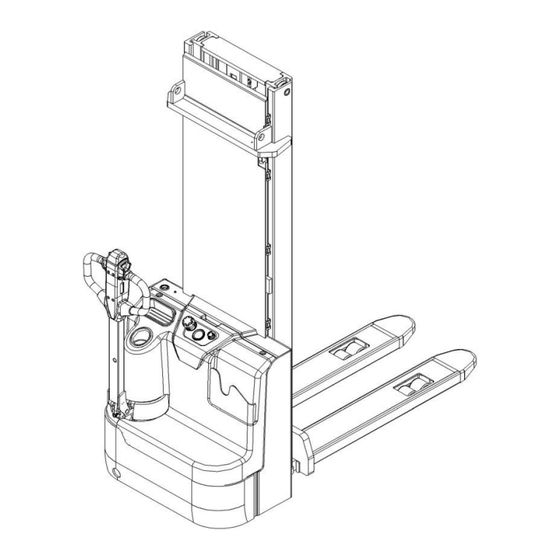
2. Specification 2.1 Main parts Pic.1 : Main parts Outer cover Multi-function handle 17 Hydraulic system Driving wheel 10 Outer cover Steering wheel 11 Meter Charge lamp 12 Key Charging Spring Wire 13 Body Emergency switch 14 tray rack Belly switch 15 Safety guard Accelerator 16 Load bearing wheels... -
Page 13: Main Technical Data
2.2 Main technical data Fig. 2: Technical data Table1: Main technical data for standard version Type sheet for industrial truck acc. to VDI 2198 15ES-XB/N Manufacturer`s type designation 1600 3600 Power (battery ,diesel, petrol, gas, manual) Battery Operator type Pedestrian... - Page 14 4.32 Ground clearance, center of wheelbase m2(mm) 4.33 Aisle width for pallets 1000X1200 crossways Ast (mm) 2293 2317 4.34 Aisle width for pallets 800X1200 lengthways Ast (mm) 2237 2261 4.35 Turning radius Wa (mm) 1450 1474 Travel speed, laden/ unladen km/h 4.4/4.7 Lift speed, laden/ unladen...
-
Page 15: Electrical System
3. Electrical system 3.1 Circuit diagram Code Item Code Item Battery FU01 80A fuse Controller Horn Pump motor FU02 130A fuse Pump contactor S1 S2 S3 S4 Tiller micro switch Emergency button Key switch Electromagnetic valve 48V charger Micro switch Charging cable CAN accelerator 0.5A fuse... -
Page 16: Main Harness
Electromagnetic brake 48V proximity switch (NC) 10A fuse Capacitor Proximity switch 3.2 Main Harness Name Name Cable -1B+-16-8-8-340 Cable -B--10-6-8-410 Cable -3B+-16-8-8-460 Cable -B--16-6-8-750 Cable -B+-16-6-8-1200 Driving Motor cable (MD) Cable -B01-16-6-6-200 Cable -B+-2.5-6-8-1500 Cable -B02-16-6-6-1250 Cable -B--2.5-6-8-1380 Cable -B03-16-6-6-120 Cable -4B+-16-8-8-100... -
Page 17: Battery (Maintenance-Free Battery)
4. Battery (Maintenance-free battery) 4.1Precautions for Battery Charging Original charger is selected to charge the battery, and strictly follow the requirements of the charger's instructions for use and maintenance. a) Forbid charging b) Charging sites should be well ventilated Battery charging process should be carried out in a well-ventilated place and should avoid moisture. Before charging, check the connector and cable, etc., to ensure that it is not damaged. -
Page 18: Battery Maintenance
● Portable batteries should be operated by professionals. 1) Park the pallet safely, turn off the key switch, and press the power switch to turn off the vehicle. 2) Open the housing. Loosen the battery holder and remove the holder. (Figures 1,2 and 3 below) 3) Unscrew the screw at the negative end (shown as'-') first, then unscrew the screw at the positive end (shown as'+') and put the harness next. -
Page 19: Charger
B Battery Pressure-Drop Test 1 The voltage of each battery is measured when the vehicle is electrified and the pump motor is operating. 2 The normal voltage shall be between 9.5 V and 12 V per cell. If the voltage on each battery is less than 9.5 V, the battery must be charged or repaired first and then continue troubleshooting. -
Page 20: Common Charger Failure
The pallet is not electrified when charging, and the electricity meter does not show the electricity quantity. After the AC power is disconnected, turn on the key switch, please check the charging protection connection of the charger when the pallet does not show the electricity. When charging, it is on. When not charging, it is closed state. After charging is complete, disconnect the AC connector from the socket and place it in the specified storage space. -
Page 21: Controller
6.Controller 6.1 Appearance... - Page 22 Diagnosis and troubleshooting There is a way to view the current fault code without a dashboard and hand-held programmer: on each controller, two LED lights are built in to indicate the entire list of fault codes. Each fault code consists of two digits. red LED: the number of times the indicator lights flicker, indicating the first number of the code;...
-
Page 23: Controller's Error Code List
Measure the diode voltage of the AC MOSFET circuit inside the controller and check if burns damage. Test according to the following table, each test item must be repeatedly tested more than 3 times. Multi meter terminal range of normal value Item Red Pen Black pen... - Page 24 CONTROLLER Heatsink temperature below - SEVERE UNDERTEMP CONTROLLER Heatsink temperature over SEVERE OVERTEMP +85C MOTOR TEMP Motor thermistor input is at the SENSOR voltage rail(0 or 10V) Motor temperature is at or MOTOR TEMP HOT above the Temperature Hot CUTBACK parameter setting THROTTLE Throttle input is out of range...
- Page 25 EMBRAKE DRIVER Electromagnetic brake driver is FAULT either open or shorted. After the EM Brake was commanded EM BRAKE FAILED TO to set and time has elapsed to allow the brake to fully engage, vehicle movement has been sensed. Emergency Reverse was EMER REV TIMEOUT activated and ran until the EMR Timeout timer expired.
- Page 26 CAN BUS LOADING PDO TIMEOUT PDO MAPPING ERROR HW FAILSAVE The hardware is defeated The CRC code of the SW FAULT application is not right LOW_BDI Low Battery capacity STEERING_SENSOR Steering sensor error When the EMR Input Type is set to type 2, the switch 2 input PARAMETER should be set as disable.
-
Page 27: Curtis Handheld Unit
7.CURTIS Handheld unit Operational considerations: Handheld unit attention function is to facilitate inspection and maintenance, without the approval of the vehicle manufacturer, the controller parameters are not allowed to adjust to avoid pallet and personal safety accidents. After the handheld unit modifies the parameters, it will be saved automatically, just turn off the key switch and restart it. - Page 28 Programmer power up Connect the handheld programmer into the control system by plugging it into the controller’s charger/programmer port. The programmer automatically powers up, and displays this screen while it loads information from the controller.
- Page 29 These three keys are blank, because their function is context-specific. At any given time, their function is shown directly above them on the LCD screen. The symbol “»” indicates more options; pressing the soft key under the “»” will scroll to another set of options. Arrow keys With these four keys you can scroll up and down and right and left, within the display.
- Page 30 If you have turned off the programmer, or if it has timed out and shut itself off, pressing the Power key will turn it on again. Favorites This key is an alternate way to bring up the Favorites menu. You can access the Favorites menu by selecting its icon in the Main Menu, or by using the Favorites key.
- Page 31 The nine menus DIAGNOSTICS MENU In the Main Menu, highlight the Diagnostics icon and press the “Select” soft key to go to the Diagnostics menu. You can return to the Main Menu at any time by pressing the Main Menu key ( ).
-
Page 32: Meter
Save.cpf File Using the Save .cpf File function in the Programming menu, you can make a backup of your present parameter settings. If you adjust the parameter values again, you can use “Save. cpf File” again to save that new collection of settings. - Page 33 (Instrument face-up) (Instrument back view)(Terminal:CF5-8TY) Port definition: 1 pin CAN-H 2 pin 3 pin 4 pin OUT 48V+ 5 pin Negative power supply(GND) 6 pin Hour meter Positive pole (48V) 7 pin CAN-L 8 pin Power supply Instrument panel display instructions 1.
- Page 34 Not shown when no fault. 3 ." FC"" is the abbreviation of Fault Code, meaning fault code; not shown when no fault. 4." FC" the box behind it contains fault specific code, When there is no fault, it is not displayed, only the hourly meter is displayed. Function Description 1.
-
Page 35: Driving Wheel
9.Driving wheel Part name refer to part catalogue On the electric side, the drive motors rotate their drive wheels, allowing pallet to move forward/backward Controlled by the controller The drive motor is connected to the controller via U, V and W lines. The controller runs the drive motor according to the input from multiple switches and sensors and the internal parameter settings. -
Page 36: Overheat Protection
9.2 Overheat protection Each drive motor is equipped with a heat sensor to prevent overheating. Once the motor is heated to 145°c (293°f), the overheating alarm is activated and the performance is limited. Speed sensor Item Specification 64 impulses per turn connector 4-pins AMP Heat sensor... -
Page 37: Drive Motor Common Fault
9.4 Drive motor common fault Problem Reason Drive motor doesn’t work Switch is not off (battery connector, key switch, proximity switch): Turn off switch. If still not running, use a voltmeter to test the power of the control panel and the current of each switch. Bad signal. - Page 38 consumes too much battery power. Check the brake adjustment. Check the wheel bearings, axles and other mechanical parts for correction to eliminate the failure. Replace the smaller friction tire. After a work shift, the pallet capacity exceeds its designed capacity without the power available: Battery positive (+) or negative (-) is in direct contact The battery is dirty , the electrolyte is on top of the with the vehicle frame (body) or drive motor...
-
Page 39: Hydraulic System
10.Hydraulic system 10.1 Hydraulic circuit LIFT CYLINDER DECLINE VALVE PRESSURE CONTROL VALVE THROTTLE PUMP AND MOTOR HYDRAULIC TANK Hydraulic diagram The hydraulic system operates other hydraulic parts through hydraulic force from pump. The main hydraulic pump is driven by the pump motor controlled by the controller. The main hydraulic pump uses the rotating force output from the motor to pressure the oil in the hydraulic tank and conveys the oil to the lifting cylinder. -
Page 40: Disassembly Of Pump Motor
The pump motor transmits the power to the main hydraulic pump by electric mode in order to pump the hydraulic oil to operate the hydraulic system. The pump motor is connected to the pump motor controller through the pump contactor and (B-)line. The controller runs the pump motor according to the input of the lifting switch and sensor. - Page 41 2.Remove piston, then remove retaining ring...
-
Page 42: Hydraulic Motor Fault
3. Remove dustproof seal and shield ring and Y-type seal 4. Remove o-seal and shield ring, then repair hose . Installation way is in reverse sequence 10.4 Hydraulic motor fault Breakdown Reason Bad connection or fuse burning. Check the battery connection. Check the key fuse. -
Page 43: Hydraulic Pump Fault
battery capacity. The battery is not fully charged during the battery charging operation. Check if battery is balance-charging (charging makes the proportion of all batteries is the same). Check if battery charger defects The battery charging interval is too long or the rechargeable battery cooling time is too short. -
Page 44: Tiller Assy
During installation, seal is cut on the shoulder of the pump or keyway. Sealed lips dry and hardened by heat. Low oil in tank Restrictions on the pump inlet pipeline Pump can’t convey hydraulic air leakage in the inlet pipe. Loose bolts. Defects in the inlet pipe. -
Page 45: Regular Maintenance
Decline switch: Press this key when need drop goods. Hoisting switch: Press this key and the goods rise. (Note: The lifting button fails when the goods are lifted to a limited position, normal protection, not malfunction) Horn switch: press this key and the horn works. (Note: Don't press this button long to avoid burning the horn) 12.REGULAR MAINTENANCE Only qualified and trained personnel are allowed to do maintenance on this truck. - Page 46 Replace protective and/or protective panels if damaged • Electrical system Check wire for damage • Check electrical connectors and terminals • Check emergency switch • Check if there is noise and damaged in driving system • Check monitor • Check if correct fuse is used •...
- Page 47 Lubricating points Lubricate the marked points according to the maintenance checklist. The required grease specification is: DIN 51825, standard grease. Load roller bearing Mast Chain Steering bearing Gear Steering roller bearing Hydraulic model: Type: H-LP 46, DIN 51524 Viscosity :41.4 - 47 Hydraulic Amount 4.5-5.5L Waste material like oil, used batteries or other must be probably disposed and recycled according to the...
- Page 48 Checking electrical fuses Location of fuses Rate 0.5A FU 01 FU 02 130A...
Need help?
Do you have a question about the 15ES-XB/N and is the answer not in the manual?
Questions and answers