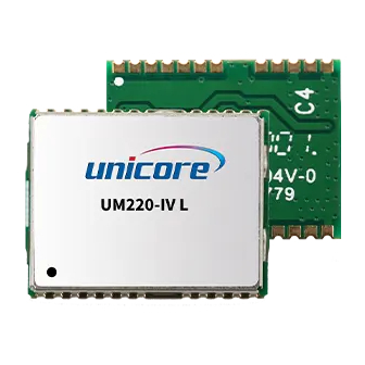
unicore UM220-IV L Reference Design
Single frequency multi-gnss timing module
Hide thumbs
Also See for UM220-IV L:
- Installation and operation user manual (32 pages) ,
- Quick start manual (9 pages)
Summary of Contents for unicore UM220-IV L
- Page 1 HARDWARE REFERENCE DESIGN WWW.UNICORECOMM.COM UM220-IV L Single Frequency Multi-GNSS Timing Module Copyright© 2009-2023, Unicore Communications, Inc. Data subject to change without notice.
- Page 2 Unicore holds the trademarks of “和芯星通”, “UNICORECOMM” and other trade name, trademark, icon, logo, brand name and/or service mark of Unicore products or their product serial referred to in this manual (collectively “Unicore Trademarks”).
- Page 3 UM220-IV L Hardware Reference Design Information, such as product specifications, descriptions, features and user guide in this manual, are subject to change by Unicore at any time without prior notice, which may not be completely consistent with such information of the specific product you purchase.
- Page 4 Foreword This document describes the hardware design of UNICORECOMM UM220-IV L module. Target Readers This manual is created for the technical personnel, who possess the expertise of GNSS products.
-
Page 5: Table Of Contents
UM220-IV L Hardware Reference Design Contents Minimum System Reference Circuit ................. 1 Reference Circuit Using a Passive Antenna .............. 3 Reference Circuit of Antenna State Detection ............4 Power Supply Requirements ..................5 Main Supply (VCC) ....................... 5 Backup Supply (V_BCKP) .................... 5... -
Page 6: Minimum System Reference Circuit
1 Minimum System Reference Circuit Supply 3.0 V ~ 3.6 V power VCC Ground all GND pins of the module Connect RF_IN to antenna, noting the 50 Ω impedance match on the circuit Upgrade the module via serial port 1, ensuring that serial port 1 can communicate ... - Page 7 UM220-IV L Hardware Reference Design Notes: When the operating voltage of the active antenna is 3.3 V, connect the VCC_RF pin to the V_ANT pin to power the antenna. User If there is a high requirement for ESD (higher than the ESD standard specified in...
-
Page 8: Reference Circuit Using A Passive Antenna
2 Reference Circuit Using a Passive Antenna To ensure the system performance, a low noise amplifier (LNA) should be added between the passive antenna and the module RF_IN. If the user has a high requirement for ESD (higher than the specified value in User Manual), the user should consider other method to power LNA rather than using VCC_RF. -
Page 9: Reference Circuit Of Antenna State Detection
Antenna state detection uses the principle of feeding current detection. If no feeding current is detected, the antenna state detection function is not supported. The detection circuit for antenna state is not integrated inside the UM220-IV L module; the antenna state detection function can be realized through the external circuit. It is... -
Page 10: Power Supply Requirements
The antenna supply voltage in the reference circuit is +3.3 V, and the power supply current shall not exceed 80 mA. If the voltage and current are not in that range, adjust the parameters to ensure that NOT (V_ANT) and NOT (AADET_N) signals match the state values in the above table. -
Page 11: Appendix
Avoid Leakage Power Description In the designing of UM220-IV L, the input interfaces (including RXD, GPIO, etc.) are connected to VCC through pull-up resistors to prevent the impact caused by the input variable state. Therefore, if there is data input on the above interfaces under the power- down mode, it can form leakage power on the module’s VCC, which may cause failure of... - Page 12 和芯星通科技(北京)有限公司 Unicore Communications, Inc. 北京市海淀区丰贤东路 7 号北斗星通大厦三层 F3, No.7, Fengxian East Road, Haidian, Beijing, P.R.China, 100094 www.unicorecomm.com Phone: 86-10-69939800 Fax: 86-10-69939888 info@unicorecomm.com www.unicorecomm.com...


Need help?
Do you have a question about the UM220-IV L and is the answer not in the manual?
Questions and answers