unicore UM220-INS Installation And Operation User Manual
Multi-gnss integrated navigation and positioning module
Hide thumbs
Also See for UM220-INS:
- Quick manual (12 pages) ,
- User manual (30 pages) ,
- Reference design (10 pages)

Related Manuals for unicore UM220-INS


Summary of Contents for unicore UM220-INS
- Page 1 INSTALLATION AND OPERATION USER MANUAL WWW.UNICORECOMM.COM UM220-INS Multi-GNSS Integrated Navigation and Positioning Module Copyright© 2009-2023, Unicore Communications, Inc. Data subject to change without notice.
- Page 2 Unicore holds the trademarks of “和芯星通”, “UNICORECOMM” and other trade name, trademark, icon, logo, brand name and/or service mark of Unicore products or their product serial referred to in this manual (collectively “Unicore Trademarks”).
- Page 3 Information, such as product specifications, descriptions, features and user guide in this manual, are subject to change by Unicore at any time without prior notice, which may not be completely consistent with such information of the specific product you purchase.
-
Page 4: Table Of Contents
Contents Contents .......................... I Overview ......................... 1 Scope ..........................1 Audience ........................1 Introduction ......................1 Product Description ...................... 1 Key Features ........................2 Interfaces ........................4 System Installation ....................5 Prerequisites ........................5 System Installation ....................... 6 Technical Specifications ..................7 Electrical Specifications .................... - Page 5 UM220-INS Series Modules User Manual Clean ........................22 Reflow Soldering ....................23...
-
Page 6: Overview
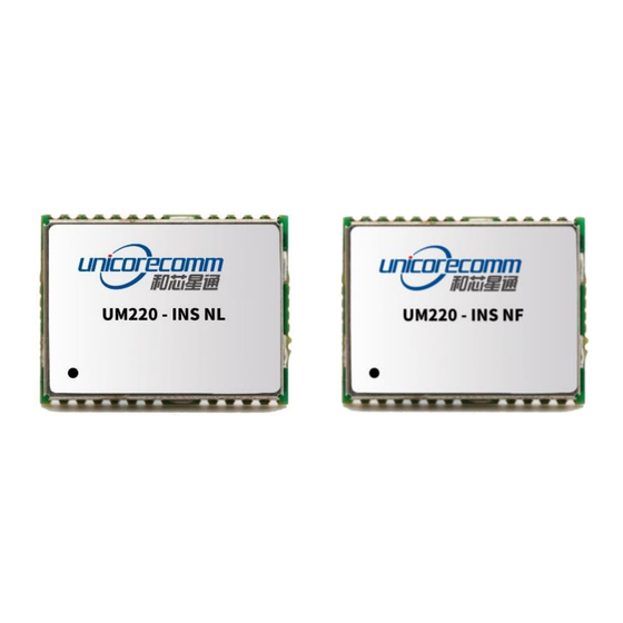
UM220-INS series product can output GNSS+MEMS inertial positioning result continuously even in tunnels and underground garages. The GNSS chip in the UM220-INS module is qualified according to AEC-Q100, and the production process complies with IATF 16949. Figure 2-1 UM220-INS Series Modules (left side: UM220-INS NL, right side: UM220-INS UC-00-M10 EN R1.8... -
Page 7: Key Features
UM220-INS NF ● ● ● ● ● ● ● ● UM220-INS series modules support multiple positioning modes including joint positioning and standalone positioning: GPS L1+SBAS+QZSS GPS+GLONASS+Galileo+SBAS+QZSS GPS+BDS+Galileo+SBAS+QZSS (default mode) ※ QZSS and SBAS are only available when GPS is enabled. - Page 8 Dimension 16.0mm*12.2mm*2.6mm Environment Operating Temperature -40° C ~ +85° C Storage Temperature -45° C ~ +90° C Input/ Output Data Interface UART*2, LVTTL. UART Baud Rate: 4800~460800bps GNSS Performance BDS B1: 1561.098MHz GPS L1: 1575.42MHz Frequency GLONASS L1: 1602+0.5625*k (MHz) Galileo E1: 1575.42MHz GPS+GLO+GA GPS+BD+GA...
-
Page 9: Interfaces
Figure 2-2 UM220-INS Series Modules Block Diagram UART UM220-INS series modules support two configurable UART ports. COM1 is the main serial port, which supports data transfer and firmware upgrade function, the signal input/output is LVTTL. The default baud rate varies according to the version of firmware,... -
Page 10: System Installation
Please check carefully whether the module is obviously loose or damaged. Please contact us or the local dealer for any problems. Figure 3-1 shows the typical installation of UM220-INS series modules with EVK suites. UC-00-M10 EN R1.8 System Installation... -
Page 11: System Installation
Step 3: Select the GNSS antenna with appropriate gain, fix it in the non-block area, using the appropriate cable to connect the antenna to UM220-INS EVK; Step 4: Connect the PC to the EVK serial port through the serial cable;... -
Page 12: Technical Specifications
4 Technical Specifications 4.1 Electrical Specifications Absolute Maximum Ratings Item Unit Description Power Supply (VCC) -0.5 Main power Backup Voltage (V_BCKP) -0.5 Backup power supply for RTC Voltage of the digital signal Digital IO (RXD1, RXD2) -0.5 pins RF_IN Max input power of antenna Storage Temperature T °... -
Page 13: Dimensions
UM220-INS Series Modules User Manual 4.3 Dimensions Symbol Min (mm) Typical (mm) Max (mm) 15.9 16.0 16.5 12.2 12.4 Figure 4-1 Mechanical Layout UC-00-M10 EN R1.8 Technical Specifications... -
Page 14: Pin Definition (Top View)
4.4 Pin Definition (Top View) Figure 4-2 Pin Assignment Name Electrical Level Description Reset nRESET LVTTL Low active, bypass if not in use Reserved TIMEPULSE LVTTL Time pulse (1PPS) Odometer speed pulse, bypass if not in use. It is strongly recommended to use, the maximum acceptable pulse frequency is 5KHz, and the minimum pulse width is WHEELTICK... -
Page 15: Pcb Packaging
Ground 4.5 PCB Packaging Figure 4-3 UM220-INS Series Modules Recommended PCB Packaging(unit: mil, in brackets: mm) In the design of PCB solder, make sure the area below the UM220-INS series modules are fully covered with solder layer. UC-00-M10 EN R1.8... -
Page 16: Hardware Design
5 Hardware Design 5.1 Design in Considerations It’s required to connect the following signals correctly to make UM220-INS series modules work properly. When the module is not powered on, it is necessary to ensure that the power supply and all GPIOs are in a high impedance state or a low level to avoid abnormal operation of the module caused by leakage. -
Page 17: Power Supply Requirements
UM220-INS Series Modules User Manual This module is a temperature sensitive device, rapid temperature changes will result in reduced performance, keep it as far away from any high-power high- temperature air and heating devices as possible. 5.2 Power Supply Requirements 5.2.1 Main Supply (VCC) -
Page 18: Antenna
5.3 Antenna If the UM220-INS series modules use an active antenna, the bias voltage V_BIAS is used to power the antenna through the feeding inductor. It’s recommended to use an independent power as V_BIAS to supply the antenna. If the antenna power supply and the module’s main supply VCC use the same power rail, the ESD, surge and overvoltage from the antenna will have an effect on VCC, which may cause damage to the module. -
Page 19: Reset
UM220-INS Series Modules User Manual 5.4 Reset If the reset pin nRESET of UM220-INS module needs to be used, the following timing requirements must be met between the nRESET and the power supply VCC. During normal operation of the module, pulling down the nRESET pin over 5 ms can also reset the module. -
Page 20: System Coordinates
WHEELTICK Figure 5-5 Odometer Connection 5.7 System Coordinates The coordinates of UM220-INS series modules must be consistent with that of the vehicles, otherwise you must perform the related configuration following the CFGROTAT command in the corresponding protocol manual. Figure 5-6 Module Coordinate System Figure 5-7 Car Coordinate System UC-00-M10 EN R1.8... -
Page 21: Installation Of The Module
1568± 20MHz. 5.8.1 Installation Instructions The UM220-INS series modules must be firmly connected to the vehicle to prevent any offsets or vibrations between the module and the vehicle. UM220-INS series modules should not be installed in the suspension part of the vehicle (with elastic part). When the vehicle is moving, any change of the vehicle coordinate system will seriously affect the UM220-INS module and prevent it from working normally. -
Page 22: Installation Options Of The Module
Free Installation (Default Mode) UM220-INS series modules integrate a three-axis gyroscope and a three-axis accelerometer, with a built-in self-calibration algorithm, which supports the free installation of the module with respect to any installation angle of the vehicle coordinate system, such as, the completely horizontal installation, inclined installation at a certain angle, and flip installation. - Page 23 UM220-INS Series Modules User Manual 0 – General installation mode, the input value of the installation angle is relatively coarse (within 10deg) 2 – Automatic installation mode, no installation angle is required. Remark: 1) Choose 2 for free installation mode and 0 for fixed installation;...
-
Page 24: Module Calibration And Notice
5.8.5 Module Calibration and Notice Self-Calibration After the installation of the UM220-INS series modules, the self-calibration is required to ensure the accuracy of the module output. In the process of the self- calibration, the module estimates installation status parameters and sensor parameters. -
Page 25: Disassembly
UM220-INS Series Modules User Manual Conditions of Completing Self-Calibration The self-calibration is triggered after power on, stop for more than three – minutes; – Good satellite visibility is required during the process of the self-calibration (the number of visible satellites is not less than six, and CN0 is above 30dB), the better the satellite observation quality is, the faster the calibration will be. -
Page 26: Package
Product QR Code (serial number) 7.2 Package Description The UM220-INS series modules use carrier tape and reel (suitable for mainstream surface mount equipment), packaged in vacuum-sealed aluminum foil antistatic bags, with a desiccant inside to prevent moisture. When using reflow welding process to weld modules, please strictly comply with IPC standard to conduct humidity control on modules. - Page 27 Thickness: 2.0mm Carrier Tape Space between: 20mm UM220-INS series modules are rated at MSL level 3, refer to the relevant IPC/JEDEC standards for baking requirements. Please access to the website www.jedec.org to download for details. The shelf life of UM220-INS series modules is one year.
- Page 28 9 Reflow Soldering In order to avoid device falling off, the module should be placed on the top of the main board during welding. Reflow soldering temperature curve is recommended as shown in figure 9-1 below (M705-GRN360 is recommended for solder paste). Note: The module can only be welded once.
- Page 29 和芯星通科技(北京)有限公司 Unicore Communications, Inc. 北京市海淀区丰贤东路 7 号北斗星通大厦三层 F3, No.7, Fengxian East Road, Haidian, Beijing, P.R.China, 100094 www.unicorecomm.com Phone: 86-10-69939800 Fax: 86-10-69939888 info@unicorecomm.com www.unicorecomm.com...
Need help?
Do you have a question about the UM220-INS and is the answer not in the manual?
Questions and answers