
Related Manuals for unicore UM220-IV L


Summary of Contents for unicore UM220-IV L
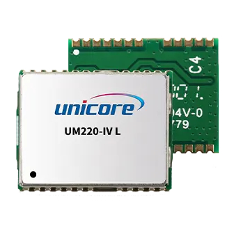
- Page 1 INSTALLATION AND OPERATION USER MANUAL WWW.UNICORECOMM.COM UM220-IV L Single Frequency Multi-GNSS Timing Module Copyright© 2009-2023, Unicore Communications, Inc. Data subject to change without notice.
- Page 2 Unicore holds the trademarks of “和芯星通”, “UNICORECOMM” and other trade name, trademark, icon, logo, brand name and/or service mark of Unicore products or their product serial referred to in this manual (collectively “Unicore Trademarks”).
- Page 3 Information, such as product specifications, descriptions, features and user guide in this manual, are subject to change by Unicore at any time without prior notice, which may not be completely consistent with such information of the specific product you purchase.
- Page 4 Foreword This document describes the product features and information of the hardware design, installation, specification and the use of UNICORECOMM UM220-IV L module. Audience This manual is created for the technical personnel, who possess the expertise of GNSS receivers.
-
Page 5: Table Of Contents
UM220-IV L User Manual Contents Contents .......................... I Product Introduction ....................1 Overview ........................... 1 Features ..........................2 Block Diagram ........................2 Performance ........................3 Precision Timing and Raw Data Output ................. 4 Pulses per Second (1PPS) ....................5 UART ..........................5 Protocol .......................... - Page 6 Layout Recommendation ..................... 22 Packaging ......................23 Product Labeling ......................23 Packaging Description ....................23 Soldering and Disassembly ..................25 Disassembly ........................25 Clean ..........................25 Reflow Soldering ......................25...
-
Page 7: Product Introduction
UM220-IV L User Manual 1 Product Introduction 1.1 Overview UM220-IV L is a GNSS multisystem, high-precision timing module, based on the low power, multisystem, high-performance SoC-UFirebird independently developed by UNICORECOMM. It supports GPS, BDS, GLONASS and Galileo, etc. Moreover, it is capable to receive and process data of two or three systems concurrently, or work on a single system. -
Page 8: Features
● ● ● ● ● ● ● IV L 1.3 Block Diagram Power UM220-IV L Supply RESET_N UART Antenna Supply & GNSS IC Supervisor Antenna Supply TCXO Crystal Figure 1- 1 UM220-IV L Block Diagram UC-00-M15 EN R1.4 Product Introduction... -
Page 9: Performance
UM220-IV L User Manual 1.4 Performance Table 1- 2 Specifications Power Voltage 3.0~3.6VDC Power Consumption 62mW @3.3V RF Input ≤2.5 VSWR Input Impedance 50Ω Antenna Gain 5~35dB Physical Characters Dimensions 17.0mm*22.4mm*2.4mm Weight 1.7g Environment Operating Temperature -40℃ ~ +85℃ Storage Temperature -40℃... -
Page 10: Precision Timing And Raw Data Output
Fixed-location timing mode is applied to static scenes. In this mode, users are required to input the exact position of receiver antenna center through CFGTM manually, which are used by UM220-IV L module to calculate the distance between the antenna and the satellite, and calculate time to perform timing service. -
Page 11: Pulses Per Second (1Pps)
UM220-IV L User Manual If the position of UM220-IV L antenna changes, the command CFGTM must be sent again to switch the timing mode back to the optimized position mode to recalibrate the antenna position. Refer to UM220-IV L_ Protocol Specification for more details. -
Page 12: Clock
1.9 Clock The industrial TCXO is built into the UM220-IV L module to ensure the stability of the clock system and the ability to capture signals quickly in weak signal environments. UM220-IV L also integrates the 32k crystal to maintain the RTC clock. When the main power supply is removed, the normal operation of the RTC can be maintained by providing V_BCKP. -
Page 13: Installation
Carefully check the module for any apparent loose or damaged components. If there are any questions, please contact Unicore or the local distributors. Figure 2- 1 Typical Installation of UM220-IV L shows the typical installation of the UM220-IV L EVK. -
Page 14: Installation
Step 1. Ensure adequate anti-static measures, such as wrist straps, workbench grounding, etc. Step 2. Open UM220-IV L EVK suite, and take out the evaluation board. Step 3. Select the GNSS antenna with the appropriate gain (the system frequency supported by the antenna should be consistent with the module) , fix it in the non-occluded area, and use the appropriate cable to connect the antenna and the UM220-IV L EB (evaluation board);... -
Page 15: Technical Specifications
UM220-IV L User Manual 3 Technical Specifications 3.1 Electrical Specifications Table 3- 1 Absolute Maximum Ratings Parameter Symbol Units Condition Power Supply Voltage -0.5 VCC Maximum Ripple Vrpp Backup Power Supply V_BCKP -0.5 Voltage Antenna Bias Voltage V_ANT VCC_RF Voltage... -
Page 16: Mechanical Specifications
3.3 Mechanical Specifications Table 3- 3 Dimensions Parameter Min (mm) Typical Value (mm) Max (mm) 22.1 22.4 23.0 16.9 17.0 17.1 2.45 2.55 2.85 2.75 2.85 3.15 0.82 Figure 3- 1 Mechanical Layout UC-00-M15 EN R1.4 Technical Specifications... -
Page 17: Pin Definition
UM220-IV L User Manual 3.4 Pin Definition Figure 3- 2 UM220-IV L Pin Assignment Table 3- 4 Pin Definition Name Electrical Level Description COM2 is for data transmission. Firmware TXD2 LVTTL upgrade is not supported. Leave this pin floating if idle. - Page 18 Name Electrical Level Description When the main power supply VCC of the module is cut off, V_BCKP supplies power to RTC and SRAM; Current value is about 50μA. V_BCKP 1.65V~3.6V V_BCKP is necessary for hot start. If you do not use the hot start function, connect V_BCKP to VCC.
-
Page 19: Pcb Packaging
3.5 PCB Packaging Figure 3- 3 UM220-IV L Recommended PCB Packaging(unit: mm, in brackets: mil) When designing PCB solder mask, make sure that the area under UM220-IV l module is completely coated with solder mask. UC-00-M15 EN R1.4 Technical Specifications... -
Page 20: Hardware Design
4 Hardware Design 4.1 Power Supply 4.1.1 Main Supply (VCC) The voltage range of VCC is 3.0 V ~ 3.6 V. Notes: The VCC initial level when power-on should be less than 0.4 V. The VCC ramp when power-on should be monotonic, without plateaus. ... -
Page 21: Antenna Design
Figure 4- 1 UM220-IV L Passive Antenna Solution To improve the performance of RF analog front-end, a low noise amplifier (LNA) can be added behind the passive antenna. UM220-IV L module provides a 3.3V power supply (VCC_RF) for LNA. Note: If the user has a high requirement for ESD (higher than the maximum specification in User Manual), the user should consider other method to power the LNA rather than using the VCC_RF pin. -
Page 22: Active Antenna
4.2.2 Active Antenna The active antenna increases the system power consumption when improving the system performance. The 3.3V Power Supply (VCC_RF) provided by the UM220-IV l module can be used to power the antenna directly if the function of detecting the state of the antenna inside the module is not used and the working voltage of the antenna is 3.3V. - Page 23 UM220-IV L Active Antenna UC6226 Coaxial Aerial Cable RF_IN DC-Block 100pF V_ANT 68nH ANT_DET_N VCC_RF R1 10Ω 10nF Figure 4- 4 UM220-IV L Active Antenna Solution Powered by External Power Supply UC-00-M15 EN R1.4 Hardware Design...
-
Page 24: Active Antenna State Detection
4.2.3 Active Antenna State Detection UM220-IV L module can detect the active antenna state including open-circuit, short- circuit and normal state. The host computer enables or disables the antenna state detection function by transmitting commands via serial ports, and receives the detected antenna state via serial ports. - Page 25 It's recommended to use the power supply from analog network. UM220-IV L UC6226 Active Antenna Coaxial Aerial Cable RF_IN V_ANT R1 10Ω 10nF ANT_DET_N VCC_RF Figure 4- 6 UM220-IV L Antenna Short-circuit Detection Powered by External Power Supply UC-00-M15 EN R1.4 Hardware Design...
- Page 26 V_ANT R1 10٠ANT_DET_N VCC_RF 560٠100nF LT6000 100K٠Figure 4- 7 UM220-IV L Antenna Short-circuit and Open-circuit Detection Powered by VCC_RF �� 2 (4-1) �� 2 +�� 3 �� _���� ���� ��1 If an external power supply is used to power the antenna, the maximum power supply voltage cannot exceed 5.5V to protect the ANT_DET_N pin.
-
Page 27: Uart
UM220-IV L User Manual 4.3 UART The two serial ports of UM220-IV L are LVTTL levels, which need to be converted through RS232 level if connected to PC. UART1 RS232 1 RS232 UM220-IV L Converter UART2 RS232 2 Figure 4- 8 Connect to PC through UART It is recommended that users reserve a test point for serial port 2 as the debug port. -
Page 28: Layout Recommendation
Try to avoid circuits below the UM220-IV L module. UM220-IV L module is a temperature sensitive device, rapid temperature changes will result in reduced performance. Keep it as far away from the high- power high-temperature air and heating devices as possible. -
Page 29: Packaging
Figure 5- 1 Product Label 5.2 Packaging Description UM220-IV L modules use carrier tape and reel (suitable for mainstream surface mount equipment), packaged in vacuum-sealed aluminum foil antistatic bags, with a desiccant inside to prevent moisture. When using reflow welding process to weld modules, please strictly comply with IPC standard to conduct humidity control on modules. - Page 30 2.0mm Carrier tape Space between: 20mm UM220-IV L module is rated at MSL level 3, refer to the relevant IPC/JEDEC standards for baking requirements. Please access to the website www.jedec.org to download for details. The shelf life of UM220-IV L module is one year.
-
Page 31: Soldering And Disassembly
UM220-IV L User Manual 6 Soldering and Disassembly 6.1 Disassembly When it is necessary to remove the module, it is recommended to melt the soldering tin of the pins on both sides of the module with an electric soldering iron and remove the module with tweezers. - Page 32 和芯星通科技(北京)有限公司 Unicore Communications, Inc. 北京市海淀区丰贤东路 7 号北斗星通大厦三层 F3, No.7, Fengxian East Road, Haidian, Beijing, P.R.China, 100094 www.unicorecomm.com Phone: 86-10-69939800 Fax: 86-10-69939888 info@unicorecomm.com www.unicorecomm.com...
Need help?
Do you have a question about the UM220-IV L and is the answer not in the manual?
Questions and answers