
Related Manuals for unicore UM681A


Summary of Contents for unicore UM681A
- Page 1 用户手册 INSTALLATION AND OPERATION USER MANUAL WWW.UNICORE.COM UM681A Multi-System Dual-Frequency High Precision RTK Integrated Positioning Module Copyright© 2009-2024, Unicore Communications, Inc. Data subject to change without notice.
- Page 2 This manual does not represent, and in any case, shall not be construed as a commitments or warranty on the part of Unicore with respect to the fitness for a particular purpose/use, the accuracy, reliability and correctness of the information contained herein.
- Page 3 Should you purchase our product and encounter any inconsistency, please contact us or our local authorized distributor for the most up-to-date version of this manual along with any addenda or corrigenda.
- Page 4 UM681A User Manual Foreword This document describes the information of the hardware, package, specification and the use of Unicore UM681A modules. Target Readers This document applies to technicians who are familiar with GNSS receivers.
- Page 5 Contents Introduction ....................1 Key Specifications ......................2 Block Diagram ........................4 Product Installation ................... 6 Preparations ........................6 Installation of EVK ......................7 Installation of the Module ....................8 2.3.1 Installation Instructions ....................8 2.3.2 Installation Angle ......................8 2.3.3 Installation Mode .......................
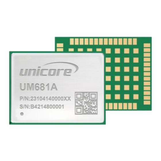
- Page 6 The GNSS chip inside the UM681A module conforms to the requirements of AEC-Q100, and the manufacturing process is in line with IATF 16949. Figure 1-1 UM681A High Precision Positioning Module...
- Page 7 Key Specifications Table 1-1 Technical Specifications Power +2.7 V to +3.6 V DC Voltage +2.7 V to +3.3 V, <100 mA LNA Feed Voltage 240 mW Power Consumption RF Input Constellation GPS/GLONASS /BeiDou/Galileo/QZSS/NavIC VSWR ≤ 2.5 Input Impedance 50 Ω Antenna Gain 15 dB to 30 dB Physical Characteristics...
- Page 8 1 Hz/5 Hz/10 Hz INS Data Update Rate 10 Hz 1PPS Accuracy (RMS) 20 ns Data Format NMEA 0183, Unicore Protocol, RTCM Environmental Specifications Operating Temperature -40 ° C to +85 ° C Storage Temperature -40 ° C to +85 ° C...
- Page 9 2. UFirebird II SoC (UC6580A) UFirebird II is the new generation RF-baseband and high-precision algorithm integrated SoC developed by Unicore. It adopts 22 nm technology and low power consumption design, supporting multi-path mitigation, anti-jamming and high precision GNSS joint positioning, providing up to 10 Hz RTK positioning solution, especially suitable for the applications which are sensitive to power and size.
- Page 10 UM681A User Manual 4. Interfaces UM681A has interfaces such as UART, I , SPI , PPS, EVENT , RTK_STAT and RESET_N. There are two UARTs. UART1 is the master serial port, supporting data transmission and firmware upgrade, and the I/O signal type is LVTTL. The baud rate can be configured by users.
- Page 11 2 Product Installation Preparations UM681A is Electrostatic Sensitive Devices (ESD) and must be installed with special precautions when handling. Please take the following protective measures before opening the anti-static plastic box. Electrostatic discharge (ESD) may cause damage to the device. All ...
- Page 12 Step 1: Make sure to take full anti-static measures, such as wearing an anti-static wristband and grounding the workbench. Step 2: Open the UM681A evaluation kit and take out the evaluation board. Step 3: Use the GNSS antenna with appropriate gain and fix it in a non-blocking area;...
- Page 13 MHz in the environment where the antenna is located. 2.3.1 Installation Instructions The UM681A must be firmly connected to the vehicle to prevent any offsets or vibrations between the module and the vehicle. UM681A should not be installed in the suspension part (elastic part) of the vehicle.
- Page 14 UM681A User Manual z axis y axis x axis The module's coordinate system The module's coordinate system consistent with that of the vehicle Rotate γ angle of the module Rotate α angle of the module Rotate β angle of the module...
- Page 15 2.3.3 Installation Mode Free Installation (Default Mode) UM681A integrate a three-axis gyroscope and a three-axis accelerometer, with the built- in self-calibration algorithm, which supports the free installation of the module with respect to any installation angle of the vehicle coordinate system, such as, the completely horizontal installation, inclined installation at a certain angle, and flip installation.
- Page 16 UM681A User Manual 2. SNRSTAT Message format: $SNRSTAT,insstatus,odostatus,InstallState,Mapstat Description: Output initial status (applicable for both fixed installation mode and free installation mode) Parameters: insstatus: Initialization status of INS -1: IMU device failure 0: Disabled 1: Initialization starts 2: The installation angle is known...
- Page 17 2.3.5 Module Calibration and Notice Self-Calibration After the installation of the UM681A, self-calibration is required to ensure the accuracy of the module output. In the process of the self-calibration, the module estimates installation status parameters and sensor parameters. The module is in GNSS navigation mode before the self-calibration is completed, and is in GNSS + INS integrated navigation mode after the self-calibration is completed.
- Page 18 UM681A User Manual After the first calibration (insstatus 3), it is still necessary to drive for about 15 minutes in the open environments to train the IMU adequately. Otherwise, the navigation accuracy may be slightly worse if the vehicle enters a complex environment such as a tunnel and garage immediately after the first calibration.
- Page 19 Pin Definition TXD1/SPIS_MISO TXD2 RXD1/SPIS_MOSI RXD2 SDA/SPIS_CSN SCL/SPIS_CLK D_SEL Top View RESET_N RTK_STAT EVENT Figure 3-1 UM681A Pin Definition Table 3-1 Pin Definition Description — Ground RF_IN GNSS antenna signal input — Ground — Reserved, leave floating — Reserved, leave floating —...
- Page 20 UM681A User Manual Description — Reserved, leave floating — Reserved, leave floating — Reserved, leave floating — Ground — Reserved, leave floating — Ground — Reserved, leave floating — Reserved, leave floating — Reserved, leave floating — Reserved, leave floating —...
- Page 21 Description — Reserved, leave floating RXD2 UART2 receiving data, LVTTL level TXD2 UART2 transmitting data, LVTTL level — Reserved, leave floating — Reserved, leave floating — Reserved, leave floating — Reserved, leave floating — Ground Power supply (+3.3 V) Power supply (+3.3 V) —...
- Page 22 UM681A User Manual Description — Reserved, leave floating Interface select pin; Use pin 42 to 45 as a SPI slave when D_SEL D_SEL = GND, as UART1 and I C When D_SEL=VCC or floating — Ground System reset; active low;...
- Page 23 Electrical Specifications 3.2.1 Absolute Maximum Ratings Table 3-2 Absolute Maximum Ratings Parameter Symbol Min. Max. Unit Remark Power Supply -0.2 Backup Battery V_BCKP -0.2 Digital Pin Voltage -0.2 Antenna RF Input Power RF_IN Storage Temperature ° C Reflow Soldering +245 °...
- Page 24 UM681A User Manual Dimensions Table 3-4 Dimensions Symbol Min. (mm) Typ. (mm) Max. (mm) 21.80 22.00 22.50 16.80 17.00 17.50 2.40 2.60 2.80 3.75 3.85 3.95 0.95 1.05 1.15 1.80 1.90 2.00 1.00 1.10 1.20 0.70 0.80 0.90 1.40 1.50 1.60...
- Page 25 Figure 3-2 UM681A Mechanical Dimensions Technical Specifications UC-00-M55 EN R1.0...
- Page 26 R1: 10 kΩ resistor is recommended Antenna Feed Design UM681A supports feeding the antenna from the outside of the module rather than from the inside. It is recommended to use devices with high power and that can withstand high voltage. Gas discharge tube, varistor, TVS tube and other high-power protective devices may also be used in the power supply circuit to further protect the module from lightning strike and surge.
- Page 27 ANT_BIAS RF_IN VCC_RF Figure 4-2 UM681A External Antenna Feed Reference Circuit Remarks: L1: feed inductor, 68nH RF inductor in 0603 package is recommended; C1: decoupling capacitor, it is recommended to connect two capacitors of 100nF/100pF in parallel; ...
- Page 28 UM681A User Manual Power-on and Power-off The VCC initial level when power-on should be less than 0.4 V. The VCC ramp when power-on should be monotonic, without plateaus. The voltages of undershoot and ringing should be within 5% VCC.
- Page 29 Grounding and Heat Dissipation Grounding and heat dissipation pad Figure 4-3 Grounding and Heat Dissipation Pad The 48 pads in the rectangle in Figure 4-3 are used for grounding and heat dissipation. In the PCB design, it is recommended to connect them to a large sized ground to strengthen the heat dissipation.
- Page 30 UM681A User Manual Recommended PCB Package Design See the following figure for the recommended PCB package design of the module UM681A. Figure 4-4 Recommended PCB Package Design Remark: For the convenience of testing, the soldering pads of the pins are designed long, exceeding the module border much more.
- Page 31 The two ways cannot be used at the same time. Hardware Interface The pin 22 (WT) of the UM681A module is used to receive the speed pulse signal (WHEELTICK) from the odometer, and the pin 23 (DIR) is used to receive the direction signal (FWD) from the odometer.
- Page 32 UM681A User Manual Table 5-1 Parameter Description of ODODATA Parameter Format Description UTC time; in the format of hhmmss.ss hh - Hour time mm - Minute ss.ss - Second speed UINT Driving speed; unit: 1e-3 m/s Driving direction: forward UINT...
- Page 33 6 Production Requirement Clean Do NOT use alcohol or other organic solvents to clean the module, otherwise it may lead to flux residues entering into the shielding shell, causing mildew and other problems. Soldering Recommended soldering temperature curve is as follows: Rising Preheating Reflux...
- Page 34 UM681A User Manual Cooling Stage Cooling slope: Max. 4 ° C/s In order to prevent falling off during soldering of the module, do not solder it on the back of the board during design, and better not go through soldering cycle twice.
- Page 35 Figure 7-1 Label Description Ordering Information Main Model Sub-model Description Automotive grade; dual-frequency RTK integrated positioning module; UM681A operating temperature: -40 ° C to +85 ° C; supporting firmware upgrade; 22 mm x 17 mm; 250 pieces/reel Packaging UC-00-M55 EN R1.0...
- Page 36 UM681A User Manual Product Packaging The UM681A module uses carrier tape and reel (suitable for mainstream surface mount devices), packaged in vacuum-sealed aluminum foil antistatic bags, with a desiccant inside to prevent moisture. When using reflow soldering process to solder modules, please strictly comply with IPC standard to conduct temperature and humidity control.
- Page 37 All dimension designs are in accordance with EIA-481-C-2003. The maximum bending degree of the carrier tape within the length of 250 mm should not exceed 1 mm (see the figure below). 250mm Figure 7-3 UM681A Reel Package Diagram Packaging UC-00-M55 EN R1.0...
- Page 38 30% circle is lavender (see Figure 7-5), you must bake the module until it turns to blue. The UM681A is rated at MSL level 3. Refer to the relevant IPC/JEDEC J-STD-033 standards for the package and operation requirements. Users may access to the website www.jedec.org to get more information.
- Page 39 和芯星通科技(北京)有限公司 Unicore Communications, Inc. 北京市海淀区丰贤东路 7 号北斗星通大厦三层 F3, No.7, Fengxian East Road, Haidian, Beijing, P.R.China, 100094 www.unicore.com Phone: 86-10-69939800 Fax: 86-10-69939888 info@unicorecomm.com www.unicore.com...
Need help?
Do you have a question about the UM681A and is the answer not in the manual?
Questions and answers