TSC MB240 Series Service Manual
Industrial barcode printer
Hide thumbs
Also See for MB240 Series:
- User manual (91 pages) ,
- Programming manual (434 pages) ,
- User manual (80 pages)

Related Manuals for TSC MB240 Series


Summary of Contents for TSC MB240 Series
- Page 1 Industrial Barcode Printer MB240 Series Thermal Transfer Direct Thermal Series Models MB240/MB340 MB240T/MB340T Service Manual www.tscprinters.com...
- Page 2 All other trademarks are the property of their respective owners. Information in this document is subject to change without notice and does not represent a commitment on the part of TSC Auto ID Technology Co. No part of this manual may be reproduced or transmitted in any form or by any means, for any purpose other than the purchaser’s personal use, without the...
-
Page 3: Table Of Contents
Table of Contents Fundamental of the System ..................................1 Printer Overview .......................................1 Front View ........................................1 Interior View ........................................2 Rear View ........................................3 Electronics ........................................4 Summary of the Board Connectors ................................4 Interface Pin Configuration ..................................7 Mechanism........................................9 Remove the Lower Front Panel ................................9 Remove the Electronics Cover ................................10 Replacing the Platen Roller Assembly .............................. - Page 4 3.12 Replacing the Gap/Black Mark Sensor Module ............................23 3.13 Cutter Module Installation (Option) ................................. 25 3.14 Peel-off Kit Installation (Option) ................................27 3.15 Slot-in Wireless Housing Installation (Option) ............................31 3.16 GPIO Interface Assembly Installation (Option) ............................32 3.17 Bluetooth Module Installation (Option) ..............................35 3.18 Linerless Kit Installation (Option) ................................
-
Page 5: Fundamental Of The System
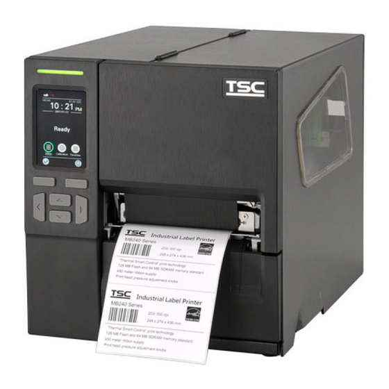
1. Fundamental of the System 1.1 Printer Overview Front View MB240/MB240T Series LED indicator LED indicator Icons and LED indicators LCD touch display Pause button Front panel buttons Feed button Media view window Media view window Paper exit chute Paper exit chute Media cover handle Media cover handle... -
Page 6: Interior View
Interior View Ribbon rewind spindle Print head pressure adjustment knob Print head release lever Ribbon supply spindle Label roll guard Label supply spindle External label entrance chute 3” core adapter Liner securing clip (Optional kit of Peel-off module ass’y) Liner rewind spindle (Optional kit of Peel-off module ass’y) Media guide bar (Optional kit of Peel-off module ass’y) Damper Ribbon end sensor... -
Page 7: Rear View
Rear View External label entrance chute Power switch USB interface (High speed mode) Slot-in Wi-Fi or GPIO interface (Option) USB host RS-232C interface Ethernet interface Power cord socket Note: The interface picture here is for reference only. Please refer to the product specification for the interfaces availability. -
Page 8: Electronics
2. Electronics 2.1 Summary of the Board Connectors Main board for MB240/ MB240T Series... - Page 9 Connector Description Remark Power switch connector Power supply (24V DC) connector DCIN2 Pin name CONFIGURATION +24V USB client connector USB1 USB host connector USB2 RS-232C connector Ethernet connector LAN1 RTC battery connector LED & key & touch-function connector CON19 Head open sensor connector CON1 LCD panel (Interface 1, SPI LCD) connector CON23...
- Page 10 Connector Description Remark Peel-off sensor connector CON10 Cutter connector CON6 Print head connector CON24 Stepping motor connector CON16...
-
Page 11: Interface Pin Configuration
2.2 Interface Pin Configuration RS-232C CONFIGURATION +5 V USB Device CONFIGURATION USB Host CONFIGURATION... - Page 12 Ethernet CONFIGURATION Cutter/peel-off Sensor Connector Description Voltage 0V: Cutter work Cutter enable 5V: Cutter stop 0V: Cutter positive cut Cutter direction 5V: Cutter negative cut 0V: Cutter stop 9 7 4 3 1 Cutter position sensor switch 3.3V: Cutter work Peel sensor receiver A/D: 0~3.3V 1 0 8 6 4 2...
-
Page 13: Mechanism
3. Mechanism 3.1 Remove the Lower Front Panel 1. Open the media cover. 2. Move the tab outward then pull the panel inward to remove the lower front panel. Lower front panel 3. Reassemble the parts in the reverse procedures. Note: When install the lower front panel, please attach the hook along the protrusion of print head mechanism. -
Page 14: Remove The Electronics Cover
3.2 Remove the Electronics Cover Open the printer right side cover and remove 2 screws (fastened by 7.5 kg±15% kg-cm) on the electronic cover as indicated. Turn the printer to left side and remove 2 screws (fastened by 7.5 kg±15% kg-cm) on the electronic cover. Remove the electronic cover. -
Page 15: Replacing The Platen Roller Assembly
3.3 Replacing the Platen Roller Assembly Refer to Remove the Lower Front Panel to remove the lower front panel. Release the platen roller bush tabs then push it to the end of mechanism on both sides as indicated. Platen roller bush tabs Pull up and remove platen roller assembly. -
Page 16: Replacing The Print Head Ass'y
3.4 Replacing the Print head ASS’Y 1. Open the media cover. 2. Push the print head release lever to open the print head mechanism. 3. Release the print head assembly by removing 1 screw (fastened by 5 kg±15% kg-cm) as indicated. Remove/Replace the print head assembly. -
Page 17: Replacing The Lcd Panel Cover Assembly
Remove the screws (touch panel: fastened by 3.5 kg±15% kg-cm; LED panel: fastened by 3.5 kg±15% kg-cm) and 1 contact spring connected on LCD panel. Connector Screw MB240T Series MB240 Series (Touch panel) (LED panel) Remove/Replace the LCD panel cover assembly. Reassemble the parts in the reverse procedures. -
Page 18: Replacing The Label Supply Spindle
3.6 Replacing the Label Supply Spindle Refer to Remove the Electronics Cover to remove the electronics cover. Remove the 2 screws (fastened by 7.5 kg±15% kg-cm) and 2 hexagon screws (fastened by 7.5 kg±15% kg-cm) on interface board; Remove the 2 screws on slot-in Wi-Fi/ GPIO interface board (if module installed). Remove 4 screws (fastened by 7.5 kg±15% kg-cm) and all connectors on the main board. - Page 19 After removing the main board, loosen the 2 screws (fastened by 7.5 kg±15% kg-cm) as indicated. Remove/Replace the label supply spindle. Screws of label spindle Label supply spindle Reassemble the parts in the reverse procedures.
-
Page 20: Replacing The Power Supply Unit
3.7 Replacing the Power Supply Unit Refer to Remove the Electronics Cover to remove the electronics cover. Remove 3 screws (fastened by 7.5 kg±15% kg-cm) as indicated below. Remove 1 screw (fastened by 7.5 kg±15% kg-cm) on main board as indicated to remove power supply unit. Remove/Replace the power supply unit. -
Page 21: Replacing The Internal Rewinder Dc Motor
3.8 Replacing the Internal Rewinder DC Motor Refer to Remove the Electronics Cover to remove the electronics cover. Remove 2 screws (fastened by 7.5 kg±15% kg-cm) and 1 cable connector on rewinder board as indicated. Remove/Replace the DC motor module. DC motor module Reassemble the parts in the reverse procedures. -
Page 22: Replacing The Internal Full Rewinder Kit (Option)
3.9 Replacing the Internal Full Rewinder Kit (Option) Refer to Remove the Electronics Cover to remove the electronics cover. Install the internal full rewinder module on the positioning holes and fix the module by fasten 3 screws (fastened by 10.5 kg± 15% kg-cm) as indicated. - Page 23 Reassemble the electronics cover. Open the media cover and install the rewinder spindle guard. Install the media guard kit. Remove the lower front panel.
- Page 24 Install and fix the lower front panel for internal rewinder by fasten 2 screws (fastened by 7.5 kg±15% kg-cm) as indicated. Complete the installation of internal full rewinder kit. Reassemble the parts in the reverse procedures.
-
Page 25: Replacing The Main Board
3.10 Replacing the Main Board 1. Refer to Remove the Electronics Cover to remove the electronics cover. 2. Remove 2 screws (fastened by 5.5 kg±15% kg-cm) on slot-in Wi-Fi/ GPIO interface board (if module installed). 3. Remove 2 screws (fastened by 5.5 kg±15% kg-cm) and 2 hexagon screws (fastened by 7.5 kg±15% kg-cm) on interface board. 4. -
Page 26: Replacing The Stepping Motor Assembly
3.11 Replacing the Stepping Motor Assembly Refer to Remove the Electronics Cover to remove the electronics cover. Remove 4 screws (fastened by 10.5 kg±15% kg-cm) and 1 connector on the stepping motor assembly. Remove/Replace the stepping motor assembly (including gears and stepping motor). Screws Connector Stepping motor assembly... -
Page 27: Replacing The Gap/Black Mark Sensor Module
3.12 Replacing the Gap/Black Mark Sensor Module Refer to Remove the Electronics Cover to remove the electronics cover. Disconnect the gap/black mark sensor connectors from the main board. Open the media cover. At the bottom of the gap/black mark sensor module, there is a plastic tab to latch the sensor assembly to the mechanism. - Page 28 Remove/Replace the gap/black mark sensor. Reassemble the parts in the reverse procedures.
-
Page 29: Cutter Module Installation (Option)
3.13 Cutter Module Installation (Option) Cutter Module Assembly Shoulder screw Screws Refer to Remove the Lower Front Panel to remove the lower front panel. Install cutter module cable on printer cable socket as indicated. - Page 30 Fasten the 2 screws (fastened by 7.5 kg±15% kg-cm) on printer mechanism as indicated. Close cutter module and fasten 1 shoulder screw (fastened by 7.5 kg±15% kg-cm) to fix hinge Note: Please make sure shoulder screw did not interfere with hinge. Cable socket Remove/Replace the cutter module.
-
Page 31: Peel-Off Kit Installation (Option)
3.14 Peel-off Kit Installation (Option) Peel-off Kit Peel-off module Media rewind spindle and media guide bar module 2 screws and 1 shoulder screw Peel-off Sensor Module Installation ◼ Refer to Remove the Lower Front Panel to remove the lower front panel. - Page 32 Install peel-off sensor module cable on printer connector as indicated. Note: Please push the cable to bottom side to prevent media stuck when peeling the label. Place the peel-off sensor module on locating holes and fix 2 screws (fastened by 7.5 kg±15% kg-cm) and 1 shoulder screw (fastened by 7.5 kg±15% kg-cm) as indicated.
- Page 33 Remove the media guide bar cover by hand. Remove the black plastic cover by push both sides of cover as indicated. Install the rewind spindle and media guide bar on electronic side. Fasten three screws (fastened by 7.5 kg±15% kg-cm) on rewind spindle and media guide bar module as indicated.
- Page 34 Disconnect the power cord than insert the rewinder power cable to the main board socket as indicated. Complete the installation of rewind spindle and media guide bar module. Reassemble the parts in the reverse procedures.
-
Page 35: Slot-In Wireless Housing Installation (Option)
3.15 Slot-in Wireless Housing Installation (Option) Refer to Remove the Electronics Cover to remove the electronic cover. Take off the slot-in wireless interface board by removing 2 screws (fastened by 5.5 kg±15% kg-cm) on rear of printer. Install the slot-in wireless housing on the rear of the printer and fix 2 screws (5.5 kg±15% kg-cm) as indicated. Connect the slot-in wireless transfer module housing board cable to the main board as indicated. -
Page 36: Gpio Interface Assembly Installation (Option)
3.16 GPIO Interface Assembly Installation (Option) GPIO Interface Assembly 1 GPIO interface board 2 hexagon screws 2 screws 2 copper pillars 1 GPIO fix board 1 GPIO transfer cable 1 GPIO board... - Page 37 Refer to Remove the Electronics Cover to remove the electronic cover. Take off the slot-in wireless interface board by removing 2 screws (fastened by 5.5 kg±15% kg-cm) on rear of printer. Install 2 copper pillars (fastened by 7.5 kg±15% kg-cm) on main board. Copper pillars Remove 2 cable connectors from the main board and insert GPIO transfer cables, then connect 2 removed cables to GPIO transfer connectors as indicated.
- Page 38 Fasten 2 screws (fastened by 5.5 kg±15% kg-cm) on GPIO fix board first. Then, aligning the GPIO board to the 2 locating holes on GPIO fix board and fasten another 2 screws (fastened by 5.5 kg±15% kg-cm) as indicated. Insert the rest connector of GPIO transfer cable to GPIO board. Locating Screws Hexagon screws...
-
Page 39: Bluetooth Module Installation (Option)
3.17 Bluetooth Module Installation (Option) Refer to Remove the Electronics Cover to remove the electronic cover. Remove 1 screw (fastened by 5 kg±15% kg-cm) on the panel assembly as indicated. Open the panel assembly and Install the Bluetooth module by fix the 2 screws (fastened by 3.5 kg±15% kg-cm) as indicated. Next, close the panel assembly. -
Page 40: Linerless Kit Installation (Option)
3.18 Linerless Kit Installation (Option) Tear / Cutter linerless kit Linerless tear / Linerless cutter Linerless cutter Linerless damper Linerless pads*2 Rubber handle Self-tapping screw*2 (TP3*9) Turning screws*2 (M3*4L) Machine screws*1 (M3*6L) Linerless tear Rubber cover Linerless pad Linerless roller Cutter tray (Linerless cutter kit only) - Page 41 Move the tab outward then pull the panel inward to remove the lower front panel. Lower front panel Refer to Replacing the Platen Roller Assembly to remove the platen roller (black) and remove the 2 screws to remove the tear bar.
- Page 42 Fasten the 2 turning screws (M3*4L; provided in the kit/ fastened by 7.5 kg±15% kg-cm) on printer mechanism as indicated. Move the label guide (green) to the outermost side to install the rubber cover and stick the linerless pad on the lower base. Rubber cover Linerless pad...
- Page 43 Install the linerless roller. Linerless roller Remove the 2 screws and replace the cover (green) from plastic to rubber. If you have the sensor bar in the linerless kit (Serial number before C24014AD0001), please refer to Replacing the Gap/Black Mark Sensor Module to replace whole sensor module.
- Page 44 Stick the 2 linerless pads on the sensor module as shown. Refer to Remove the Electronics Cover to remove the electronic cover. Remove one screw to replace the linerless damper. Linerless damper...
- Page 45 Plug the tear (or cutter) module mini DIN cable connector into the printer receptacle. 10. Place the tear (or cutter) module in position and use the 1 machine screw (M3*6L/ fastened by 7.5 kg±15% kg-cm) provided in the kit to install the tear (or cutter) module on the lower support assembly. Linerless tear Linerless cutter...
- Page 46 11. For the linerless cutter module, the cutter tray is mounted on the cutter panel as required. Linerless cutter with tray...
-
Page 47: Troubleshooting
4. Troubleshooting 4.1 Common Issues Problem Possible Cause Recovery Procedure ◼ The power cord is not properly connected. ◼ Plug the power cord in printer and outlet. Power indicator does not illuminate ◼ The power switch is closed. ◼ Switch the printer on. Carriage Open The printer carriage is open. - Page 48 Problem Possible Cause Recovery Procedure ◼ Reload the supply. ◼ Ribbon and media is loaded incorrectly. ◼ Clean the print head. ◼ Dust or adhesive accumulation on the print ◼ Clean the platen roller. head. ◼ Adjust the print density and print speed. Poor Print Quality ◼...
- Page 49 Problem Possible Cause Recovery Procedure ◼ LCD panel is dark and keys are not ◼ The cable between main PCB and LCD panel Check if the cable between main PCB and LCD is working is loose. secured or not. LCD panel is dark but the LEDs are ◼...
-
Page 50: Knob Adjustment
4.2 Knob Adjustment 4.2.1 Print head Pressure Adjustment Knob Print head Pressure Adjustment Knob has 6 levels’ adjustment for 1~2” and 3~4” width media. Different number means different pressure to the media. Due to printer’s paper alignment is on left side of the mechanism, different media width requires the different pressure. -
Page 51: Ribbon Tension Adjustment Knob
4.2.2 Ribbon Tension Adjustment Knob Ribbon Tension Adjustment Knob has 5 positions for adjustment. Due to the ribbon is aligned to the inbound of print mechanism, different width of ribbon may need to adjust the tension adjustment knob to avoid the ribbon wrinkle and get the best print quality. -
Page 52: Mechanism Fine Adjustment To Avoid Ribbon Wrinkles
4.2.3 Mechanism Fine Adjustment to Avoid Ribbon Wrinkles Ribbon wrinkle is related to the media width, thickness, print head pressure balance, ribbon film characteristics, print darkness setting…etc. In case the ribbon wrinkle happens, please follow the instructions below to adjust the printer parts. Ribbon Tension Adjustment Knob has 5 indexes for adjustment. - Page 53 Wrinkle happens from label lower right to upper left direction Feed Direction Make sure the Print head Pressure Adjustment Knob is in correct position for the current media. Ex: 1~2”, 3~4” ◼ Turn the screw clockwise per level and print to see if the winkle has g1. ◼...
- Page 54 Wrinkle happens from label lower left to upper right direction Feed Direction Make sure the Print head Pressure Adjustment Knob is in correct position for the current media. Ex: 1~2”, 3~4” ◼ Turn the screw counterclockwise per level and print to see if the winkle has g1. ◼...
-
Page 55: Maintenance
5. Maintenance This session presents the clean tools and methods to maintain the printer. For Cleaning ◼ Depending on the media used, the printer may accumulate residues (media dust, adhesives, etc.) as a by-product of normal printing. To maintain the best printing quality, you should remove these residues by cleaning the printer periodically. Regularly clean the print head and supply sensors once change a new media to keep the printer at the optimized performance and extend printer life. - Page 56 Cleaning Tools Cotton swab ◼ Lint-free cloth ◼ Brush with soft non-metallic bristles ◼ Vacuum cleaner ◼ 75% Ethanol (for disinfecting) ◼ 99% Isopropyl alcohol (for printhead and platen roller cleaning) ◼ Genuine printhead cleaning pen ◼ Mild detergent (without chlorine) ◼...
- Page 57 Please refer to Linerless Cleaning Kit User Manual for more information. Clean as needed or after printing every 1 km. Linerless Please determine the Printer maintenance intervals based on actual usage.
-
Page 58: Revision History
Revision History Date Content Editor 2023/5/3 Added ch. Linerless Kit Installation Camille 2023/5/8 Added Linerless cutter tray Camille 2023/6/28 Added ch. Cleaning the Printer after Linerless Printing Camille 2023/12/15 Updated the template Camille 2024/1/09 Updated ch. Linerless Kit Installation Camille 2024/3/8 Camille Updated the Maintenance section... - Page 59 www.tscprinters.com...
Need help?
Do you have a question about the MB240 Series and is the answer not in the manual?
Questions and answers