Advertisement
Quick Links
Advertisement

Related Manuals for Vestfrost VLS 026 RF SSD


Summary of Contents for Vestfrost VLS 026 RF SSD
- Page 1 CORPORATE PRESENTATION...
- Page 2 1. Overview of VLS 026_056 RF SDD 2. General required maintenance 3. Vital components 4. Warning 5. Required basic Tools 6. Replacement of components ▪ Thermostat ▪ Starting Device ECU ▪ Thermometer ▪ Thermostat Sensor ▪ Fan ▪ Fuse 7. Trouble shooting 8.
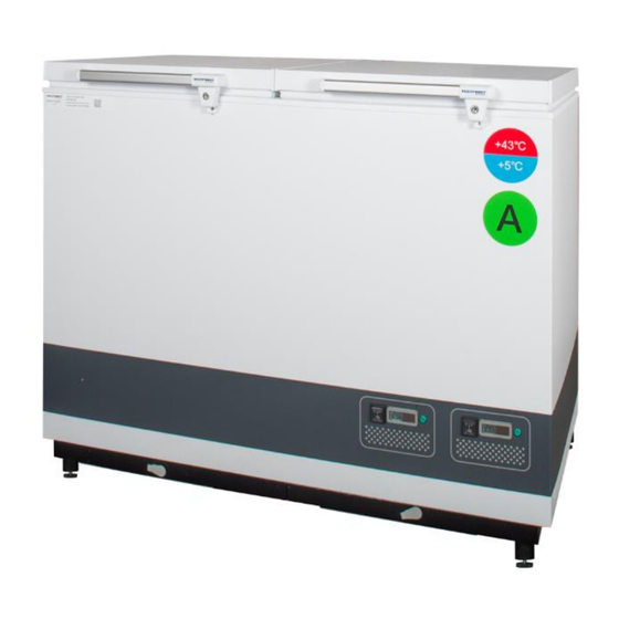
- Page 3 Combined Vaccine Chest Refrigerators and Freezer SDD – Solar Direct Drive WHO PQS Approved Codes: • E003/091 • E003/092 Technical specifications: • +43°C hot zone • Grade A • Compressor Secop BD35K • Refrigerant R600a • Galvanized pre-painted cabinet • Inner lining pre-painted aluminium •...
- Page 4 Daily Check: Monitor Temperature Internal lid is placed properly Lid fits and lock tight to cabinet Lid gasket not faulty Monthly: Clean grill for compressor compartment 6 Month: Clean condenser coils Yearly: Check electrical connections and components Check electrical connections, cables, wirings from PV panel system Regularly: Clean Solar Panels Check Solar Panels are not shaded at any time of the day...
- Page 5 Position Item no Description 8-036510214 Compressor 5712 702090013 Thermostat 5727 6520845 Starting Device ECU 0899 7020311 Thermostat sensor PV Solar Panel Kit CORPORATE PRESENTATION...
- Page 6 Before any repair job be aware of following! WARNING: Before servicing or cleaning the appliance, disconnect it from power source. WARNING: Danger risk of fire or explosion. Flammable refrigerant used. To be repaired only by trained personnel. CORPORATE PRESENTATION...
- Page 7 1. Flexible socket wrench 2. Socket wrench - size 7mm 3. Nose plier 4. Phillips screwdriver 5. Torx screwdriver - size t10+t20 Screwdriver - size 1,0x6,0 7. Screwdriver – size 0,6x3,5 8. Multimeter Proposed additional service kit/items Sealing kit Tar tape Extra self-tapping screws CORPORATE PRESENTATION...
- Page 8 CORPORATE PRESENTATION...
- Page 9 How to get access to the motor compartment. On the backside you will find two engine compartments each covered with a metal grill Unscrew the two screws on each grill Remove the grill CORPORATE PRESENTATION...
- Page 10 Wiring Diagram Vaccine Refrigerator Thermostat probe Thermostat CORPORATE PRESENTATION...
- Page 11 The thermostat is placed in the left corner of the compressor compartment Front/Screen Side Back CORPORATE PRESENTATION...
- Page 12 1. Remove the two screws holding the fan/controller bracket in place 2. Pull the fan/controller bracket 3. Flip it around to allow easy access to thermostat 4. Remove the two clamps holding the thermostat in place CORPORATE PRESENTATION...
- Page 13 5. To remove the clamps press in the middle and slide it back 6. After clamps have been removed use a screwdriver to remove the two power wires 7. Now pull the controller out to allow easy access to the remaining wires CORPORATE PRESENTATION...
- Page 14 8. Exchange the wires 1/1 from the old thermostat to the new 9. Reverse the previous step 7 to 1 install the new thermostat CORPORATE PRESENTATION...
- Page 15 Wiring Diagram Waterpack Freezer Thermostat probe Thermostat CORPORATE PRESENTATION...
- Page 16 The thermostat is placed in the left corner of the compressor compartment Thermostat wire/sensor Adjustment Back withelectric terminals CORPORATE PRESENTATION...
- Page 17 1. Screw the adjustment dial off 1. Adjustment: Rotation clockwise warm to cold Important Always keep in coldest position 2. Screw the size 14 bolt holding the thermostat in place off 3. Remove the two power wires CORPORATE PRESENTATION...
- Page 18 4. Remove sealing kit from thermostat wire tube 5. Carefully pull the thermostat wire out CORPORATE PRESENTATION...
- Page 19 6. Push the new thermostat wire back up with care and make sure it is inserted all the way. 7. IMPORTANT! Remember to put the sealing kit back in place CORPORATE PRESENTATION...
- Page 20 Mangler CORPORATE PRESENTATION...
- Page 21 Starting device The starting device Back is mounted to the left side of the Front compressor with terminal board 1: Loosen the 2: Place a phillips screw a screwdriver in the couple of turns small vent in the plastic cover 3: Unclick plactic 4: Use a cover/starting...
- Page 22 Video How to dismount CORPORATE PRESENTATION...
- Page 23 Video How to install CORPORATE PRESENTATION...
- Page 24 Thermometer The thermometer is display placed in at the front of the appliance The temperature 1: Dismount the probe is placed temperature inside the sensor cover by compartment of the loosen the 2xtorx appliance screws – size 10 2: Remove wire 3: remove the sealing two sensors from...
- Page 25 5: Temperature 4: Remove black sensor sealing tar-kit and gently pull the white wire until the probe is visible IMPORTANT! 6: Thermometer comes with wire When re-mounting and sensor the new thermometer make sure the wire sealing plug is placed properly IMPORTANT! When re-mounting the new...
- Page 26 1: Dismount the The thermostat temperature sensor is placed sensor cover by inside the loosen the 2xtorx compartment of the screws – size 10 appliance 3: Remove wire 2: remove the sealing two sensors from the housing 4: Unplug the probe connector 5: Remove black from thermostat...
- Page 27 6: The thermostat sensor comes with ▪ Probe ▪ Wire ▪ Cable sockets IMPORTANT! IMPORTANT! When re-mounting When re-mounting the new the new thermometer thermometer make sure the remember to wire sealing plug is properly seal the placed properly wire feedthrough Tar kit CORPORATE PRESENTATION...
- Page 28 The fan is placed in the motor compartment on the fan/controler bracket 1: Dismount the 2: Loosen the two screws fan/controller bracket as discribed in section - ”thermostat replacement” 3: Unplug the red and black power cable from the terminal bord CORPORATE PRESENTATION...
- Page 29 If the fuse is burned 1. Use the small It need to be replaced. fuse- tool The fuse is placed on the supplied fan/controller bracket together with spare fuses in the small plastic bag together with appliance or a plier . 2.
- Page 30 Procedure of compressor switch. 1: WARNING! Drain coolant R600a from refrigeration system by vacuum suction 2: IMPORTANT! Blow refrigeration system with NO/Nitrogen 3: Cut A: Suction and pressure tube B: Capillary tube C: Dry filter 4: Dismount starting device ECU 5: Dismount old compressor 6: Insert new compressor 7: Install starting device ECU...
- Page 31 Video CORPORATE PRESENTATION...
- Page 32 CORPORATE PRESENTATION...
- Page 33 CORPORATE PRESENTATION...
- Page 34 Service technician to check Is the green diode in the control panel on (Power check) Is the internal temperature inside the acceptable range of +2° to +8° Is the vaccine compartment clean and without condensation (water) Is the Compressor is running ...
- Page 35 If contacting Vestfrost Solutions technical support please supply below information: 1. Model 2. Serial number 3. What is the issue Rating plate Serial no Model CORPORATE PRESENTATION...
- Page 36 CORPORATE PRESENTATION...
Need help?
Do you have a question about the VLS 026 RF SSD and is the answer not in the manual?
Questions and answers