
Related Manuals for Gema Smart Series


Summary of Contents for Gema Smart Series
- Page 1 Operating instructions and spare parts list Smart W Series 4000 /6000/9000 Powder Coating Booth March 2012 Revision A ...
- Page 2 To the best of our knowledge and belief, the information contained in this publication was correct and valid on the date of issue. ITW Gema makes no representations or warranties with respect to the contents or use of this publication, and reserves the right to revise this publication and make changes to its content without prior notice.
-
Page 3: Table Of Contents
Entering the booth / booth cleaning Repairs About this manual General Information Description of operation Field of Application Operation Function Smart series coating booth Exhaust air system (recirculation) Filter cleaning Powder circuit Technical Specifications Smart series coating booth Electrical Specifications Pneumatic data... - Page 4 Operating Function check Safety Recommendations Switching on the booth Procedure Switching off the booth Procedure Cleaning the filter Static pressure readings Collector Final filter Setting the pressure switch Setting the pulse down timer Maintenance Maintenance Schedule Quick booth cleaning Procedure Cleaning of the booth and collector Procedure Cleaning the collector dropout hopper...
-
Page 5: General Safety
These safety recommendations should be read and understood on all points before the Smart Series coating booth is operated. Safety symbols (pictograms) Below are listed the warnings found in the ITW Gema operating instruction manual and their meaning. -
Page 6: Technical Safety Regulations For Stationary Electrostatic Spraying Equipment
Observation of the operation, support, and maintenance instructions specified by the manufacturer is also included as part of the conformity of use. The Smart Series coating booth should be used, put into operation and maintained by trained personnel, who shall be aware of and familiar with the possible risks involved. -
Page 7: Safety Conscious Working
If breakdowns occur due to the use of other parts, any guarantee becomes void. 9. If ITW Gema electrostatic powder spraying equipment is used in combination with products from other manufacturers, their safety rules and regulations must also be applied. - Page 8 ITW Gema electrostatic powder spraying equipment is switched off by means of a general switch or, if available, by means of an emergency shutdown switch. Each of the components can be switched on and off during operation with the respective switches.
-
Page 9: Notes On Special Types Of Hazards
All maintenance activities carried out on the ITW Gema equipment must be carried out with the equipment switched off. The operating company must train the personnel and require them to observe this point. -
Page 10: Safety Recommendations For Powder Coating
The defective element must be replaced or repaired immediately. Only original ITW Gema replacement parts should be used. If damages occur due to the use of other parts, the guarantee will be void. - Page 11 14. For your safety, use only additional accessories and equipment indicated in the service instructions. The use of non-ITW Gema replacement parts can lead to risk of injury. Use only original ITW Gema replacement parts! 15.
-
Page 12: Special Safety Measures
Special safety measures Installation Installation, which is done by the customer, must be carried out according to local regulations. Before beginning plant work, a check should be made that there are no foreign objects in the booth or in the ducting (intake and exhaust air). -
Page 13: About This Manual
General information This instruction manual contains all the important information necessary to work with your Smart Series coating booth. It will guide you during the start-up and will also provide indications and advice for optimal use of your new powder coating system. -
Page 14: Description Of Operation
Description of function Field of application The Smart Series is designed exclusively for electrostatic coating with organic powder. Any other use is considered non-compliant. The manufacturer is not liable for damages derived from improper use of this equipment; the final user is solely responsible! -
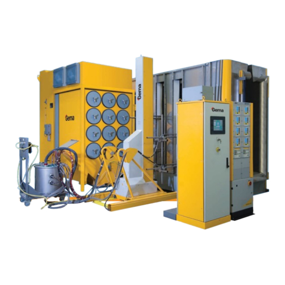
Page 15: Smart Series Coating Booth
Smart Series coating booth PARA OPTIFLEX UNICAMENTE 2A MAX. Coating Booth-Series Smart (Smart Batch Booth Shown illustrated) 1. Recovery Unit 2. Final Filter 3. Pulse Down Manifold 4. Cartridge Filter 5. Collector Dropout Hopper Booth Cabin Smart W Series Booth Page 13 ... -
Page 16: Exhaust Air System (Recirculation)
Exhaust Air System (Recirculating air) The fan of the exhaust system is located in the fan housing above the cartridge filters. Air is drawn into the interior of the booth, passing through the cartridge filters, and is returned to the environment through the final filter as clean air. -
Page 17: Technical Specifications
Technical specifications Smart Series coating booth Electrical technical characteristics Smart 4000 6000 9000 Input voltage 230/460/575 V, 60 Hz Pneumatic data Smart 4000 6000 Input pressure Min 90 psig – Max 125 psig Recommended input pressure 90 psig Water vapor content of compressed air 1.3 g/m... -
Page 18: Start-Up
Start-up General information Note: Before starting up it may be necessary to run a Function Check. A start-up should be carried out before the start of every shift and after the booth has been standing idle for long period! Preparation for start-up Procedure Observe the safety regulations... -
Page 19: Start-Up
Start-up Procedure 1. Enable the compressed air circuit, and check that the input pressure is set to 90 psig bar. 2. Switch the main powder disconnect on at the booth electrical panel. A green light will illuminate indicating that the panel has been power on. -
Page 20: Operating
Operation Function check Check the grounding of the booth and other connected equipment, and if necessary, ground. Safety instructions Observe the safety recommendations! Switching on the booth Procedure 1. Switch the main powder disconnect on at the booth electrical panel. A green light will illuminate indicating that the panel has been power on. -
Page 21: Cleaning The Filter
Cleaning the filter The cartridge filters are cleaned cyclically during booth operation. The cleaning cycle is initiated automatically when the booth is turned on. Cleaning times are preset at the factory. If the differential pressure reaches maximum level (6” WC on the cartridge filter and 3.5”... -
Page 22: Setting The Pressure Switch
Setting the Pressure Switches for the Magnehelic Gauges Set the pressure switches only while the system off. Cut off a spare five foot piece of 1/4” tubing. Plug it into the cartridge filter fitting on the back of the electrical panel. -
Page 23: Maintenance
Maintenance Maintenance Schedule Maintenance Maintenance tasks intervals Blow through the powder hose Daily or after each shift Clean the outside of the gun, and check parts for wear. Quick clean the booth (see chapter “Quick booth cleaning”). Check for damaged cartridge, if necessary, replace (see chapter, “Replacing a cartridge filter”). -
Page 24: Quick Booth Cleaning
Quick booth cleaning Attention: The cartridge filters must never be cleaned with compressed air guns ! Procedure Switch on the booth. Remove powder from the walls of the booth by using compressed air or a squeegee so that any powder adhering to the inside falls to the booth floor or is drawn into the collector Any powder on the booth floor should then be pushed into the collector dropout hopper. -
Page 25: Cleaning The Collector Dropout Hopper
Cleaning the collector dropout hopper Procedure 1. Switch on the booth. 2. Ensure fluidization pressure for dropout hopper is set to proper level. 3. If applicable, remove the powder from the dropout hopper by using the transfer pumps. 4. Lower the dropout hopper and remove it from underneath the collector, then manually remove or vacuum any remaining powder in the hopper. -
Page 26: Replacing Spare Parts
Replacing spare parts General The replacement of spare parts must only be carried out by specialized personnel! The booth must be switched off before replacing spare parts. Spare parts should be ordered according to the Spare Parts List. Replacing a cartridge filter Before replacing a cartridge filter a filter cleaning operation must be carried out: 1. -
Page 27: Replacing The Final Filters In The Fan Housing
Replacing the final filters in the fan housing Procedure 1. Final filters are located on the outside of the collector housing. 2. Use the correct size wrench to loosen the nuts fastening the filter support bracket to the housing. 3. - Page 28 9. Reinstall the solenoid if needed, and then remount the valve onto the manifold inside the collector housing (seal the valve on the manifold with Teflon tape.) 10. Close up the collector and open the booth main air supply. 11. Turn the booth power on and listen for any compressed air leaks and proper pulsing cleaning sounds.
-
Page 29: Troubleshooting
Troubleshooting General Note: Repairs to the electrical parts of the booth must only be undertaken by trained personnel! Problems Solutions Powder not Assure there is compressed air going to the transfer pump. Check transfer pump transferring from regulator setting. Check for worn pump insert, check for obstruction in transfer collector hose or pump. - Page 30 Blow out the lines and inspect the “T” tube. Run a parallel “test” tube and check correctly. all fittings for leaks. Contact the ITW Gema service department before making any relocation changes. The booth switches Fault in the fan motor, the motor protection is activated. Turn off the main switch, off, the lamp let the motor cool down, activate the motor protection and switch on the booth;...
-
Page 31: Spare Parts List
Example: Ø 8/6 mm, 8 mm outside diameter / 6 mm inside diameter WARNING! Only original ITW Gema spare parts should be used, as in this way protection against explosion is preserved. If damage results from the use of non-original spare parts, the guarantee will be void! ... -
Page 32: Replacement Parts
Replacement Parts Collector components #105176 – GASKET,COLL,1.5”X2”x54”,SMART #139741 – FILTER,CRT,36X12.7,100SQF #139787 - VALVE,DIA,PLUSE,1.0”,SMART BOOTH #139792 - DIAPHRAGM KIT,1.0”, SMART BOOTH #109619 – FILTER,FINAL,24”X19”X3.5” #140392 – FLUIDPLATE,SMART B/W,2,3,4,6KCFM #140535 – FLUIDPLATE,SMART B/W,9KCFM Transfer Pump components (if used) 139748 – TRANSFER PUMP, ASSY 139745 –... - Page 33 Smart W Series Booth Page 31 Operation Manual March 2012 ‐ Revision A ...
Need help?
Do you have a question about the Smart Series and is the answer not in the manual?
Questions and answers