Table of Contents
Advertisement
Quick Links
EN
Rev. 00
1017 565
Quick reference guide
Manual equipment
OptiFlex Pro Base Kit
Detailed information and detailed spare parts lists can be found
in the corresponding operating instructions: via the Gema app or
www.gemapowdercoating.com/en/support/operation-manuals.
Translation of the original operating instructions
Advertisement
Table of Contents

Related Manuals for Gema OptiFlex Pro Base Kit


Summary of Contents for Gema OptiFlex Pro Base Kit
- Page 1 Rev. 00 1017 565 Quick reference guide Manual equipment OptiFlex Pro Base Kit Detailed information and detailed spare parts lists can be found in the corresponding operating instructions: via the Gema app or www.gemapowdercoating.com/en/support/operation-manuals. Translation of the original operating instructions...
- Page 2 To the best of our knowledge and belief, the information contained in this publication was correct and valid on the date of publication. Gema Switzerland GmbH makes no representations or warranties with respect to the contents or use of this publication, and reserves the right to revise this publication and make changes to its content without prior notice.
-
Page 3: Table Of Contents
Safety General information ....................7 Basic safety instructions ..................7 Product specific security regulations ..............8 OptiFlex Pro Base Kit Intended use ......................13 Structure ........................ 14 Scope of delivery ....................15 Typical characteristics – properties of the functions ..........15 Technical Data ...................... - Page 4 Fault clearance Faults ........................63 Spare parts list Ordering spare parts ..................... 65 OptiFlex Pro Base Kit – Spare parts list ............... 66 OptiFlex Pro Base Kit – Spare parts ..............67 Pneumatic group ....................68 PowerClean module set** ..................69 OptiStar CG21 Gun control unit................
-
Page 5: About These Instructions
General information This operating manual contains all important information which you require for the working with the OptiFlex Pro Base Kit. It will safely guide you through the start-up process and give you references and tips for the optimal use when working with your powder coating system. -
Page 6: Presentation Of The Contents
Figure references in the text Figure references are used as cross references in the descriptive text. Example: "The high voltage (H) created in the gun cascade is guided through the center electrode." 6 About these instructions OptiFlex Pro Base Kit... -
Page 7: Safety
If this product is to be used for other purposes or other substances outside of our guidelines then Gema Switzerland GmbH should be consulted. -
Page 8: Product Specific Security Regulations
If this product is to be used for other purposes or other substances outside of our guidelines then Gema Switzerland GmbH should be consulted. - Page 9 The use of other parts can lead to risk of injury. Only original Gema spare parts should be used! Repairs must only be carried out by specialists or by authorized Gema service centers. Unauthorized conversions and modifications can lead to injuries and damage to the equipment and invalidate the Gema Switzerland GmbH guarantee.
- Page 10 As a general rule for all powder spraying installations, persons with The stay for persons pacemakers should never enter high voltage areas or areas with with cardiac pacemakers electromagnetic fields. Persons with pacemakers should not enter areas is forbidden with powder spraying installations! 10 Safety OptiFlex Pro Base Kit...
- Page 11 The operating personnel must wear electrically conductive, steel-toe footwear (e.g. leather soles). The operating personnel should hold the gun with bare hands. If gloves are worn, these must also conduct electricity. Safety 11 OptiFlex Pro Base Kit...
- Page 12 Rev. 00 04/19 12 Safety OptiFlex Pro Base Kit...
-
Page 13: Optiflex Pro Base Kit
Any other use is considered non-compliant. The manufacturer is not responsible for any incorrect use and the risks associated with such actions are assumed by the user alone! OptiFlex Pro Base Kit 13 OptiFlex Pro Base Kit... -
Page 14: Structure
All information about the OptiStar 4.0 (Type CG21) manual gun control unit can found in the documentation for that equipment (enclosed with this manual)! OptiFlow injector All information about the OptiFlow injector will be found in the corresponding enclosed documentation! 14 OptiFlex Pro Base Kit OptiFlex Pro Base Kit... -
Page 15: Scope Of Delivery
In moist or tropical environments, any moisture is driven from the injector, powder hose and powder gun. The color change is also accelerated during non-extreme color switches. fig. 3 OptiFlex Pro Base Kit 15 OptiFlex Pro Base Kit... -
Page 16: Technical Data
8 mm Max. input pressure 5.5 bar / 80 psi Max. water vapor content of the 1.3 g/m³ compressed air Max. oil vapor content of the 0.1 mg/m³ compressed air 16 OptiFlex Pro Base Kit OptiFlex Pro Base Kit... - Page 17 Hose internal diameter (mm) Ø 11 Hose length (m) Total air volume (Nm³/h) Powder output (g/min) Powder output 135 150 100 185 215 145 235 270 185 280 320 220 OptiFlex Pro Base Kit 17 OptiFlex Pro Base Kit...
- Page 18 Maximum relative humidity linearly decreasing to 50 % relative humidity at 40 °C Environment not for wet environment Degree of pollution of the 2 (in accordance with DIN EN intended environment 61010-1) 18 OptiFlex Pro Base Kit OptiFlex Pro Base Kit...
- Page 19 The specified value is applicable only for this product itself and does not take into account external noise sources or cleaning impulses. The sound pressure level may vary, depending on the product configuration and space constraints. Rating plate fig. 4 OptiFlex Pro Base Kit 19 OptiFlex Pro Base Kit...
- Page 20 Rev. 00 04/19 20 OptiFlex Pro Base Kit OptiFlex Pro Base Kit...
-
Page 21: Assembly / Connection
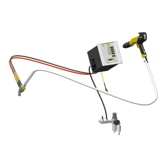
5: Connecting guide – overview Gun cable Compressed air hose Manual gun Injector Electrode rinsing air hose Fluidizing air hose Powder hose 10 Maintenance unit Supplementary air hose 11 OptiStar Control unit Conveying air hose Assembly / Connection 21 OptiFlex Pro Base Kit... - Page 22 ► Check ground connections with Ohm meter and ensure 1 MOhm or less. The compressed air must be free of oil and water! Close the unused connections with the provided dust protection caps! 22 Assembly / Connection OptiFlex Pro Base Kit...
-
Page 23: Start-Up
6 The remainder of the start-up procedure for the gun is explicitly described in the operating instructions for the OptiStar CGxx manual powder gun control unit (chapter "Initial start-up" and "Daily start-up")! Start-up 23 OptiFlex Pro Base Kit... -
Page 24: Setting The Device Type
ATTENTION A wrong parameterization leads to various malfunctions! ► For more on this, please also see the operating instructions for the gun control unit! 24 Start-up OptiFlex Pro Base Kit... -
Page 25: Operation
► The manual equipment may only be operated in conjunction with a sufficiently powerful suction unit (such as Gema Classic Open booth). Place powder hopper on the mobile trolley... - Page 26 Select the desired program (01-20) Program 20 active Change the coating parameters as required Programs 01-20 are preset at the factory but can be modified at any time, after which they are automatically stored. 26 Operation OptiFlex Pro Base Kit...
- Page 27 Adjust the total air volume on the gun control unit with the T3/T4 keys – Adjust the total air volume according to the corresponding coating requests correct powder cloud too little total air Setting the powder output Operation 27 OptiFlex Pro Base Kit...
- Page 28 (deflector plate, flat jet nozzle) ≈ 0.1 Nm³/h ≈ 0.5 Nm³/h too much electrode rinsing air If in this display level is no operation for 3 seconds, the first display level is switched over independently. 28 Operation OptiFlex Pro Base Kit...
- Page 29 – The powder should only be touched gently, but should be "cooked" regularly and is also to be stirred using a rod Close again the cover Operation 29 OptiFlex Pro Base Kit...
-
Page 30: Rinsing Mode
On manual coating equipment type F, the injector must be disconnected prior to cleaning procedure, on type B, the suction unit must be lifted, and on type S, the powder container must be empty. Detach the injector START = 30 Operation OptiFlex Pro Base Kit... - Page 31 Manual equipment with optional PowerClean module (system parameter P01= 1 or P01=2) The rinsing mode can only be activated from standby mode (main menu display, no powder conveying). START = Operation 31 OptiFlex Pro Base Kit...
- Page 32 PowerClean impulse by pressing the gun trigger a (manual) second time STOP = OR the cleaning mode is terminated automatically. After completion of the PowerClean procedure, the controller switches back to coating mode. 32 Operation OptiFlex Pro Base Kit...
-
Page 33: Color Change
13. Vacuum up the hopper and in particular the bottom 14. Clean container with a cloth 15. Reassemble the powder hopper 16. Fill with new powder 17. Prepare the manual coating equipment with new powder for start-up Operation 33 OptiFlex Pro Base Kit... - Page 34 Rev. 00 04/19 34 Operation OptiFlex Pro Base Kit...
-
Page 35: Decommissioning / Storage
If in disuse for several days Separate from power mains Clean guns, injectors and powder hoses (see therefore the corresponding user manuals) Turn off the compressed air main supply Decommissioning / Storage 35 OptiFlex Pro Base Kit... - Page 36 Rev. 00 04/19 36 Decommissioning / Storage OptiFlex Pro Base Kit...
-
Page 37: Maintenance / Repairs
Weekly maintenance Clean powder container, injector, rinsing module** and powder gun. Check the control unit grounding connections to the coating booth, the suspension devices of the work pieces, or the conveyor chain Maintenance / Repairs 37 OptiFlex Pro Base Kit... - Page 38 The gun is designed to require only a minimum amount of maintenance. Clean the gun with dry cloth, see chapter "Maintenance" Check connection points to powder house. Replace the powder hoses, if necessary. 38 Maintenance / Repairs OptiFlex Pro Base Kit...
-
Page 39: Cleaning
Clean the integrated gun tube with the brush supplied if necessary Blow through the gun with compressed air again Clean the powder hose Reassemble the gun and connect it Cleaning the powder container Maintenance / Repairs 39 OptiFlex Pro Base Kit... - Page 40 Vacuum up the hopper and in particular the bottom Clean container with a cloth 10. Reassemble the powder hopper Do not refill the powder container until just before the next use! 40 Maintenance / Repairs OptiFlex Pro Base Kit...
-
Page 41: Fault Clearance
Injector or nozzle on the Clean the corresponding part gun trigger is pressed injector, powder hose or powder gun clogged Insert sleeve in the injector is Clean/replace clogged Fluidization not running see below Fault clearance 41 OptiFlex Pro Base Kit... - Page 42 Fluidizing air is set too low on Set the fluidizing air correctly the control unit Throttle motor defective Contact local Gema representative Airmover pressure incorrectly Adjust Powder flows out of the powder hopper 42 Fault clearance OptiFlex Pro Base Kit...
-
Page 43: Optistar Cg21
For further information, see the corresponding operating manual, which can be found on the accompanying CD. Design and function Overall view Fig. 7 Front plate with control and Back panel with interfaces display elements Enclosure OptiStar CG21 43 OptiFlex Pro Base Kit... - Page 44 Display of predefined operating modes or display of cleaning mode during cleaning – Display of readiness for pairing the Bluetooth module with a mobile device (green) – Display of an active connection (blue) 44 OptiStar CG21 OptiFlex Pro Base Kit...
- Page 45 Display background illumination (0-8) Input keys and switches fig. 10: Input keys and switches Designation Function Input keys for desired values and system T1-T8 parameters Switch between display levels T10-T11 Program change OptiStar CG21 45 OptiFlex Pro Base Kit...
- Page 46 – Display of the ID number (press for a short time) – Switching on the rinsing mode (PowerClean) with optional PowerClean module – Terminating the rinsing mode (PowerClean) with optional PowerClean module 46 OptiStar CG21 OptiFlex Pro Base Kit...
-
Page 47: Fault Clearance
Here is a list of all possible help codes for this Gun control unit: Code Description Criteria Remedy Pneumatics: – PowerClean valve not connect or replace connected – Valve defective Contact a Gema service PowerClean valve – Connection cable center defective – Mainboard defective Fault clearance 47 OptiFlex Pro Base Kit... - Page 48 EEPROM error Contact a Gema service erroneous center Throttle motors: Throttle motor or needle Contact a Gema service Conveying air reference jammed, limit switch defective, center position not found error in motor throttle 48 Fault clearance OptiFlex Pro Base Kit...
- Page 49 It is possible that an error is only displayed for a short time, but after the acknowledgement it will disappear. In this case, it's recommended to switch off the control unit and switch it on again (reset by restarting). Fault clearance 49 OptiFlex Pro Base Kit...
- Page 50 Rev. 00 04/19 50 Fault clearance OptiFlex Pro Base Kit...
-
Page 51: Optiselect Pro Gm04
Gun cable Threaded sleeve Powder hose connection Shaft 10 Powder hose quick release connection (grounded) Rear part with hook 11 Electrode rinsing air Remote control connection SuperCorona connection 12 Trigger Gun handle OptiSelect Pro GM04 51 OptiFlex Pro Base Kit... -
Page 52: Available Accessories
Multi-spray adapter – Rinsing module (with corresponding OptiStar control unit only) – Various adapters for connection to earlier generations of control units – Gloves, anti-static **for more information, see spare parts list 52 OptiSelect Pro GM04 OptiFlex Pro Base Kit... -
Page 53: Technical Data
85 °C (+185 °F) Protection type IP64 Approvals 0102 II 2 D PTB 19 ATEX 5001 Dimensions OptiSelect Pro GM04 Weight 550 g Processible powders OptiSelect Pro GM04 Plastic powder Metallic powder Enamel powder OptiSelect Pro GM04 53 OptiFlex Pro Base Kit... - Page 54 Rev. 00 04/19 54 OptiSelect Pro GM04 OptiFlex Pro Base Kit...
-
Page 55: Fault Clearance
Solenoid valve in the control Replace unit defective No conveying air: – Throttle motor defective Contact local Gema – representative Solenoid valve defective Front plate defective Contact local Gema representative Fault clearance 55 OptiFlex Pro Base Kit... - Page 56 Bend or damage to air lines to Check air lines to injector injector Insert sleeve in the injector Replace or insert it worn or not inserted Fluidization not running see above 56 Fault clearance OptiFlex Pro Base Kit...
-
Page 57: Optiflow Ig07
CD. Structure Overall view Fig. 13 Check valve unit Injector housing (supplementary air) Release trigger Powder hose quick release Check valve unit connection (conveying air) Powder hopper connection OptiFlow IG07 57 OptiFlex Pro Base Kit... -
Page 58: Powder Volume Setting For Optiflow Injector
If a very large powder output is required, it is recommended to select a larger powder hose internal diameter (Ø 12 mm). It should to be noted, that if irregular or pumping conveying occurs, as a rule, the total air is set too low! 58 OptiFlow IG07 OptiFlex Pro Base Kit... -
Page 59: Maintenance / Repairs
Clean the injector body with compressed air which is free of oil and water. – Any contamination can be seen through the opening of the hopper fitting If the injector is severely fouled, it must be dismantled Maintenance / Repairs 59 OptiFlex Pro Base Kit... -
Page 60: Cleaning The Check Valve Units
► Blow off the filter elements from the inside to the outside! ► Do not immerse the filter elements in fluidities or solvents! ► Never remove the supporting ring! 60 Maintenance / Repairs OptiFlex Pro Base Kit... -
Page 61: Changing The Cartridge
Rev. 00 04/19 fig. 15 Connection/plug Filter element O-ring 3.1 Supporting ring Changing the cartridge Maintenance / Repairs 61 OptiFlex Pro Base Kit... - Page 62 Rev. 00 04/19 62 Maintenance / Repairs OptiFlex Pro Base Kit...
-
Page 63: Fault Clearance
Conveying vacuum Increase the powder Gun achieving only too low quantity and/or total poor spray profile air volume on the control unit Cartridge worn, Replace or install the clogged or not cartridge. inserted Fault clearance 63 OptiFlex Pro Base Kit... - Page 64 Rev. 00 04/19 64 Fault clearance OptiFlex Pro Base Kit...
-
Page 65: Spare Parts List
When using the spare parts from other manufacturers the explosion protection is no longer guaranteed. If any damage is caused by this use all guarantee claims become invalid! ► Only original Gema spare parts should be used! Spare parts list 65 OptiFlex Pro Base Kit... -
Page 66: Optiflex Pro Base Kit - Spare Parts List
Rev. 00 04/19 OptiFlex Pro Base Kit – Spare parts list OptiStar CG21 gun control unit – complete (see corresponding operating manual) OptiSelect Pro GM04 Manual powder gun – complete (see corresponding user manual) OptiFlow IG07 injector – complete (see corresponding user manual) Pneumatic connection for supplementary air Quick release connection –... -
Page 67: Optiflex Pro Base Kit - Spare Parts
Rev. 00 04/19 OptiFlex Pro Base Kit – Spare parts fig. 16: Spare parts list 67 OptiFlex Pro Base Kit... -
Page 68: Pneumatic Group
Pressure gauge – 0-10 bar, 1/8" 1008 049 Distribution block 1017 816 Screw-in nipple – 1/4", Ø 8 mm 265 136 Plug – Ø 8 mm 238 023 # Wearing part fig. 17: Pneumatic group 68 Spare parts list OptiFlex Pro Base Kit... -
Page 69: Powerclean Module Set
Plastic tube – Ø 8/6 mm, black 103 152* O ring – Ø 16x2 mm, NBR70, anti-static (2x) (not shown) Cable tie (not shown) * Please indicate length # Wearing part fig. 18: PowerClean module set** Spare parts list 69 OptiFlex Pro Base Kit... -
Page 70: Optistar Cg21 Gun Control Unit
OptiStar CG21 gun control unit – complete, without item 4 1015 203 Front plate – complete, see corresponding spare parts list Enclosure Backplate – complete, see corresponding spare parts list Cover 1015 249 4 ––––– fig. 19 70 Spare parts list OptiFlex Pro Base Kit... -
Page 71: Front Plate And Power Pack
Front plate gasket 1015 236 Membrane keypad Spacer sleeve – Ø 3.6/7x5 mm Display 1015 220 Washer – Ø 3.2/7x0.5 mm Locknut – M3 Power pack – 24 VDC 1009 849 Fig. 20 Spare parts list 71 OptiFlex Pro Base Kit... -
Page 72: Inside Back Plate
1001 521 Fluidizing pad – 1/8" 237 264 Screw – M4x16 mm 1013 925 Plastic tube – Ø 8/6 mm 103 152* Motor throttle – complete 1008 012 * Please indicate length 72 Spare parts list OptiFlex Pro Base Kit... -
Page 73: Inside Back Plate
Rev. 00 04/19 Inside back plate fig. 21: OptiStar CG21 Spare parts list 73 OptiFlex Pro Base Kit... -
Page 74: Connecting Material
Mains cable – Schuko 382 485 Mains cable – USA 382 507 Mains cable – GB 382 515 Mains cable – AUS 382 523 Mains cable – China 1000 993 * Please indicate length 74 Spare parts list OptiFlex Pro Base Kit... -
Page 75: Connecting Material
Rev. 00 04/19 Connecting material fig. 22 Spare parts list 75 OptiFlex Pro Base Kit... -
Page 76: Optiselect Pro Gm04 - Spare Parts List
Threaded sleeve (see corresponding spare parts list) Nozzle (see corresponding spare parts list) Cable lock 1017 685 Screw – M3x20 mm 1017 674 Contact strip 1018 707 Fitting bush 1018 708 76 Spare parts list OptiFlex Pro Base Kit... - Page 77 Powder hose – Ø 10 mm (not shown) 1001 673*# Powder hose – Ø 11 mm (not shown) 105 139*# * Please indicate length # Wearing part fig. 23: OptiSelect Pro GM04 – spare parts Spare parts list 77 OptiFlex Pro Base Kit...
-
Page 78: Powerclean™ Module (Option)
O ring – Ø 16x2 mm, anti-static 1007 794# Fluidizing tube bearing 1007 356 Fluidizing tube 1007 355 Retaining bracket 1009 524 O-ring – Ø 27x2 mm 1009 525 # Wearing part fig. 24 78 Spare parts list OptiFlex Pro Base Kit... -
Page 79: Supercorona
Rev. 00 04/19 SuperCorona SuperCorona PC.. 1018 291# # Wearing part fig. 25 Spare parts list 79 OptiFlex Pro Base Kit... -
Page 80: Accessories
NF22 1008 145 Profiles/big flat NF40 parts (standard 1018 166 nozzle) NF40* 1018 165 NF24 1008 326 Large surfaces 1008 142 NF24* 1008 147 * not suitable for angled nozzles 80 Spare parts list OptiFlex Pro Base Kit... - Page 81 Threaded sleeve Deflectors Ø 16 mm NS04 Suitable for 331 341 large surfaces 1008 150 Ø 24 mm NS04 1008 152 331 333 1008 151 1007 229 Ø 32 mm 331 325 Spare parts list 81 OptiFlex Pro Base Kit...
- Page 82 ► The extensions (150 mm/300 mm) may be connected TO ONLY ONE ADDITONAL extension (150 mm/300 mm), if necessary. 82 Spare parts list OptiFlex Pro Base Kit...
- Page 83 1007 742 1007 740 Ø 16 mm Suitable for NS09 331 341 large 1008 259 surfaces NS09 Ø 24 mm 1008 258 1008 257 331 333 Ø 32 mm 331 325 Spare parts list 83 OptiFlex Pro Base Kit...
- Page 84 * Please indicate length Other accessories 150 ml 500 ml Application cup 1004 552 1002 069 Gun extension cables L=6 m 1002 161 Gloves, anti-static (1 pair) 800 254 84 Spare parts list OptiFlex Pro Base Kit...
-
Page 85: Optiflow Ig07 - Spare Parts List
Powder hose – 74 type, POE, Ø 15/10 mm, with conductive strip 1001 673*# Powder hose – 75 type, POE, Ø 18/12 mm, with conductive strip 1001 674*# * Please indicate length # Wearing part Spare parts list 85 OptiFlex Pro Base Kit... -
Page 86: Optiflow Ig07 - Spare Parts
Rev. 00 04/19 OptiFlow IG07 – spare parts fig. 26 86 Spare parts list OptiFlex Pro Base Kit... - Page 87 Fault clearance ....... 41, 47, 55, 63 Start-up ............23 Figure references in the text ......6 Storage ............35 Input keys and switches ........45 Technical Data ..........53 Intended use ............ 13 Maintenance ..........37, 59 Index 87 OptiFlex Pro Base Kit...
- Page 88 Rev. 00...
Need help?
Do you have a question about the OptiFlex Pro Base Kit and is the answer not in the manual?
Questions and answers