
Related Manuals for Gema FPS16


Summary of Contents for Gema FPS16
- Page 1 Operating instructions and spare parts list Fresh powder system FPS16 Translation of the original operating instructions...
- Page 2 To the best of our knowledge and belief, the information contained in this publication was correct and valid on the date of publication. Gema Swit- zerland GmbH makes no representations or warranties with respect to the contents or use of this publication, and reserves the right to revise this publication and make changes to its content without prior notice.
-
Page 3: Table Of Contents
Function description Field of application ....................7 Overview ......................... 7 Versions ..................... 7 Technical Data FPS16 Fresh powder system .................. 9 Conveying performance ................9 Electrical data .................... 9 Pneumatic data ..................10 Dimensions ....................10 Container specifications (big bag) ............10 Equipment description Structure ........................ - Page 4 Troubleshooting General information ....................29 Spare parts list Ordering spare parts ..................... 31 FPS16 Fresh powder system – spare parts list ............ 32 FPS16 Fresh powder system – spare parts ............33 Fluidizing/suction tube ..................34 Fluidizing/suction tube ..................35 Control ........................
-
Page 5: General Safety Regulations
General safety regulations This chapter sets out the fundamental safety regulations that must be fol- lowed by the user and third parties using the FPS16 Fresh powder sys- tem. These safety regulations must be read and understood before the Fresh powder system is put into operation. -
Page 6: Product-Specific Safety Measures
If it is to be used in a manner outside the scope of the safety concept, then corresponding measures must be taken. NOTE: For further information, see the more detailed Gema safety regula- tions! 4 • General safety regulations FPS16... -
Page 7: About This Manual
► Before working with the device, organize the required documents and read the section on "Safety regulations". ► Work should only be carried out in accordance with the instructions in the relevant documents. ► Always work with the complete original document. About this manual • 5 FPS16... -
Page 9: Function Description
The powder is aspirated in pulses by a vacuum, and sub- sequently transported with conveying air. Versions The FPS16 Fresh powder system is available either with one or with two powder pumps (FPS16-2). The FPS16-2 version permits a powder transport from the large powder container to two different destinations. -
Page 11: Technical Data
V 07/21 Technical Data FPS16 Fresh powder system Conveying performance FPS16 3500-5000 g/min for each pump* (according to the material to be Conveying performance conveyed, suction and conveying length, powder preparation etc.) up to 8 m (5 kg/min conveying per-... -
Page 12: Pneumatic Data
V 07/21 Pneumatic data FPS16 Compressed air 5-8 bar / 101-145 psi max. 0.5 Nm³/h for lifting procedure max. 12 Nm³/h for each PP0x Air consumption Powder pump max. 0.5 Nm³/h for fluidization Max. water vapor content 1.3 g/m³ Max. oil vapor content 0.1 mg/m³... -
Page 13: Equipment Description
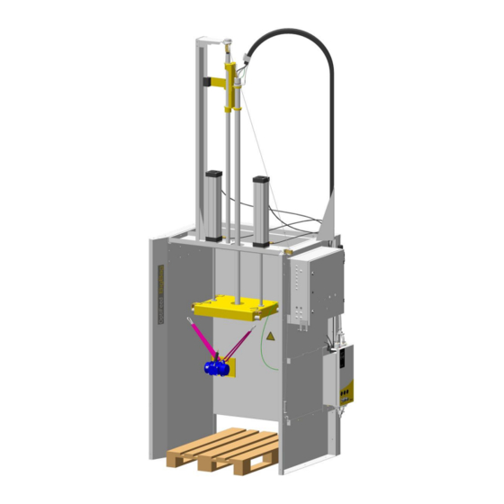
V 07/21 Equipment description Structure The FPS16 Fresh powder system consists of: Fig. 1: Structure Fluidizing/suction tube Vibrating plate Control Lifting device for container Powder pump Lifting device for fluidiz- ing/suction tube Support Equipment description • 11 FPS16... -
Page 14: Support
The laterally attached powder pump aspirates the powder, if required, by the fluidizing/suction tube and ensures the transport to the powder con- tainer in the coating plant. Please observe the operating manual of the corresponding powder pump! 12 • Equipment description FPS16... -
Page 15: Function
If the powder shortage will not be reset by the up/down pro- cedure during a defined time, an alarm message for the operating per- sonnel will be released. Equipment description • 13 FPS16... -
Page 16: Operating And Display Elements
This red indicator lamp illuminates, if the powder flow sensor does not detect powder during a defined time. Now the large powder con- tainer must be checked by the operating personnel and probably be changed 14 • Equipment description FPS16... -
Page 17: Control Module
V 07/21 Control module Fig. 3: Control module Power pack Additional module Main module Equipment description • 15 FPS16... -
Page 19: Start-Up
Analog input 0-10 V / pressure sensor for pump 2 Main module outputs Output Description main solenoid valves Solenoid valve – lift cylinder Warning lamp - no powder Potential-free contact – no powder (max. voltage 230 VAC) Start-up • 17 FPS16... -
Page 20: Additional Module Inputs
Description Lift/lower Fluidizing air P min = 0.5 bar Compressed air supply, pinch valves (FPS16-2 version only) P max. = 3.0 bar Powder connections The powder hose must be connected according to the corresponding powder pump(s). -
Page 21: Start-Up
Set parameter not to be used not to be used Parameter input display: Block number The value set at Param- eter Time ON The value set at Param- eter Time OFF Current time Start-up • 19 FPS16... -
Page 22: Entering And Selecting A Menu Option
B2 ap- pears. Edit Move Quit the program mode with the ESC key and return to the normal display Shut down ATTENTION! The control unit continues to process the program in the "Parame- terization" operating mode! 20 • Start-up FPS16... - Page 23 The no powder signal B017 Debouncing of B014 T = 3.0 secs. must be present for a de- fined duration NOTE: For the adjustment and the operation of the powder transport, the corresponding powder pump documentation must be observed! Start-up • 21 FPS16...
-
Page 24: Powder Flow Detection
– Powder flow Pump Powder container full Craters in the powder container/container empty Backpressure in the powder hose Threshold value below (variable) Threshold value not reached – Powder flow not OK Pump Craters in the powder container/container empty 22 • Start-up FPS16... -
Page 25: Procedure Description
The upper threshold value limits the correct functionality of the powder transport. The exceeding signifies a malfunction (powder hose is clogged or bent). Example: Default value 900 corresponds to 2.2 bar (suction and conveying proce- dure of the pump will be influenced) Start-up • 23 FPS16... -
Page 27: Container Change / Color Change / Cleaning
A color change with a partially emptied large container must take place in same way. In this case, it's important that the partially emptied container is well locked for storage. Container change / color change / cleaning • 25 FPS16... -
Page 28: Cleaning
V 07/21 Cleaning In order to achieve a long-term trouble-free operation of the FPS16 Fresh powder system, it is important that also the environment is kept clean every day. The fresh powder system, as well as the fluidizing/suction tube does not require a special cleaning. -
Page 29: Maintenance
V 07/21 Maintenance General information The FPS16 Fresh powder system does not require a special mainte- nance. However, the following steps are to be observed regularly: Check grounding resistance. – The measured value should not exceed 10 ohm. – Measuring points: suspension bolts –> main grounding connec- tion at rear of unit Constant compressed air quality –... -
Page 31: Troubleshooting
Lay out fluidizing air hose as straight as possible Too much fluidizing Reduce the fluidizing air present air with the pressure regulator in the con- trol cabinet Fluidizing/suction Lift the fluidiz- tube clogged ing/suction tube and clean it Troubleshooting • 29 FPS16... - Page 32 Repair powder pump tive No signal for "fresh Check wiring powder requirement" Check level sensor signal Pinch valve defective, Check/replace pinch excess air suction valve hose Pinholing will not be Contact an Gema solved service center 30 • Troubleshooting FPS16...
-
Page 33: Spare Parts List
Ø 8/6 mm, 8 mm outside diameter (o/d) / 6 mm inside diameter (i/d) ATTENTION! Only original Gema spare parts should be used, because the explo- sion protection will also be preserved that way. The use of spare parts from other manufacturers will invalidate the Gema guarantee conditions! Spare parts list •... -
Page 34: Fps16 Fresh Powder System - Spare Parts List
V 07/21 FPS16 Fresh powder system – spare parts list FPS16-1 Fresh powder system – complete 1004 063 FPS16-2 Fresh powder system – complete 1004 064 Fluidizing/suction tube – complete (see corresponding spare parts list) Pinch valve (see corresponding spare parts list) -
Page 35: Fps16 Fresh Powder System - Spare Parts
V 07/21 FPS16 Fresh powder system – spare parts Fig. 4: Spare parts Spare parts list • 33 FPS16... -
Page 36: Fluidizing/Suction Tube
Connector – NW5, 1/8" 237 272 Quick release connection – NW5, Ø 8 mm 203 181 Connection box, single 1004 034 Powder hose – Ø 23/16 mm 1003 307*# * Please indicate length # Wear parts 34 • Spare parts list FPS16... -
Page 37: Fluidizing/Suction Tube
V 07/21 Fluidizing/suction tube Fig. 5: Fluidizing/suction tube Spare parts list • 35 FPS16... -
Page 38: Control
Solenoid valve – 3-1/8" 1001 002 Valve coil – 24 VDC 254 142 Pressure regulator – 0.5-6 bar 264 342 Elbow joint – 1/8", Ø 8 mm 251 372 Control cabinet (empty) 1003 504 36 • Spare parts list FPS16... -
Page 39: Control
V 07/21 Control Fig. 6: Control Spare parts list • 37 FPS16... -
Page 40: Pinch Valve
223 069 Screw – 5x26 mm 1006 263 Pinch valve hose – NW15 1006 256# Elbow joint – 1/4", Ø 8 mm 254 029 * Please indicate length # Wear parts Fig. 7: Pinch valve 38 • Spare parts list FPS16... - Page 41 V 07/21 Spare parts list • 39 FPS16...
Need help?
Do you have a question about the FPS16 and is the answer not in the manual?
Questions and answers