
Related Manuals for Gema OptiCenter OC08


Summary of Contents for Gema OptiCenter OC08
- Page 1 Rev. 02 1011 546 Operating instructions and Spare parts list Powder management system OptiCenter OC08 Translation of the original operating instructions...
- Page 2 To the best of our knowledge and belief, the information contained in this publication was correct and valid on the date of publication. Gema Switzerland GmbH makes no representations or warranties with respect to the contents or use of this publication, and reserves the right to revise this publication and make changes to its content without prior notice.
-
Page 3: Table Of Contents
Cleaning hose ..................21 Powder bag cone ..................21 Vibrating trolley** ..................22 Powder hopper** ..................22 Ultrasonic sieve system US07** .............. 23 Powder recovery system** ............... 23 Powder feed to guns** ................24 Table of contents • 3 OptiCenter OC08... - Page 4 Preparation for start-up ..................55 Basic conditions ..................55 Basic information ..................55 Inserting the SD card .................... 56 Inserting SD card ..................56 Removing SD card .................. 56 Parameter description ..................56 4 • Table of contents OptiCenter OC08...
- Page 5 Physical requirements ................104 Hazard notes ..................104 Maintenance during storage ................104 Maintenance schedule ................104 Maintenance works ................104 Storage and transport of the operating panel ........104 Disposal Introduction ......................107 Table of contents • 5 OptiCenter OC08...
- Page 6 Disposal regulations ................107 Materials ....................107 Disassembly of component groups ..............107 Spare parts list Ordering spare parts ................... 109 OptiCenter OC08 ....................110 Cone trolley ......................111 Fluidizing/suction unit ..................112 OptiSpeeder – complete ..................113 OptiSpeeder – Cover ..................114 OptiSpeeder –...
-
Page 7: About These Instructions
General information This operating manual contains all the important information which you require for the working with the OptiCenter OC08. It will safely guide you through the start-up process and give you references and tips for the optimal use when working with your powder coating system. -
Page 8: Structure Of Safety Notes
Possible consequences of the danger ► Prevention of the danger Software version This document describes the operation of the product OptiCenter OC08 with software version starting from 1.4.12. See chapter "Checking the software version" on page 51. 8 • About these instructions... -
Page 9: Presentation Of The Contents
Presentation of the contents Figure references in the text Figure references are used as cross references in the descriptive text. Example: "The high voltage (H) created in the gun cascade is guided through the center electrode." About these instructions • 9 OptiCenter OC08... - Page 10 Rev. 02 04/21 10 • About these instructions OptiCenter OC08...
-
Page 11: Safety
If this product is to be used for other purposes or other substances outside of our guidelines then Gema Switzerland GmbH should be consulted. -
Page 12: Product Specific Security Regulations
– It must be ensured, that all components are earthed according to the local regulations before start-up. For further security information, see the more detailed Gema safety regulations! WARNING Working without instructions Working without instructions or with individual pages from the instructions may result in damage to property and personal injury if relevant safety information is not observed. -
Page 13: Transport
Use only technical personnel who are trained in operating the respective equipment (e.g. a crane). If there are any uncertainties, please contact Gema Switzerland GmbH. Packing material Not necessary for the internal transport. For external transport: see chapter "Decommissioning / Storage" on page 103. -
Page 14: Mode Of Transportation
The OptiCenter must not be placed fully in the horizontal position, since it is not designed for this purpose. ► In case of doubt contact Gema Switzerland GmbH! Loading, transferring the load, unloading Suitable lifting equipment is to be used for all procedures. -
Page 15: Product Description
The powder management center is designed for easy and clean handling of the coating powder and is operated via a touch panel. The center will only operate in combination with Gema powder conveyors, which are designed to convey coating powder to the spray guns. -
Page 16: Field Of Application
Conveying – Fresh powder directly from the (original) powder bag – Fresh powder from a Gema fresh powder system – Powder directly from the optional powder hopper – Precision conveying from the OptiSpeeder to the applicators –... -
Page 17: Technical Data
Rev. 02 04/21 Technical Data Electrical data OptiCenter OC08 Connected load 230 V+E+N Frequency 50/60 Hz Protection type IP54 Approvals II 3 D Pneumatic data OptiCenter OC08 Inlet pressure min. 6.5 bar Water vapor content of max. 1.3 g/m³ compressed air Oil content of compressed air max. -
Page 18: Dimensions
Rev. 02 04/21 Dimensions OptiCenter OC08 24 guns 36 guns Area* 1900 x 1700 1900 x 1950 (width x depth) (mm) 2100 (2250 - OptiFeed Overall height (mm) connection) Weight (kg) OptiCenter base weight loaded* with electrostatic and system control... -
Page 19: Design And Function
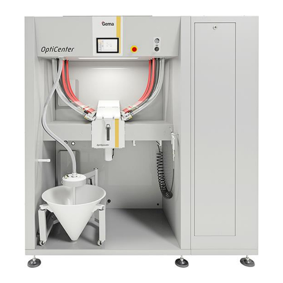
Main switch OptiSpeeder fluidization OptiFlow injectors OptiSpeeder 10 Powder hopper venting connection Powder bag fixation Powder bag cone with vibrator Touch Panel All necessary operating procedures are activated by the Touch Panel. Fig. 5: Product description • 19 OptiCenter OC08... -
Page 20: Compressed Air Indicators
Rev. 02 04/21 Compressed air indicators fig. 6: Gema default values after installation 0.5 bar AirMover (normal operation) 30Q1 3 bar OptiSpeeder fluidizing air 30Q3 2 bar Powder container fluidizing air 33Q2 2 bar Fluidizing air Fluidizing/suction unit 33Q1 Operating elements Fig. -
Page 21: Cleaning Hose
9 Powder bag cone – Capacity up to 25 kg – Can be swiveled for easy powder emptying – Fluidizing/suction lance – Fresh powder pump connection – Recovery powder pump connection Fig. 10 Product description • 21 OptiCenter OC08... -
Page 22: Vibrating Trolley
Suitable for metallic powders – Level sensor optionally available When using the powder hopper, the venting hose must be connected to the connector , and the ball valve (10) must be open during the entire operation. 22 • Product description OptiCenter OC08... -
Page 23: Ultrasonic Sieve System Us07
Optional powder return into the powder bag cone or into the powder hopper or into the extraction system – Plug position (extraction system) monitored by sensor The parameterization of this option is done on the Touch Panel. Fig. 14 Product description • 23 OptiCenter OC08... -
Page 24: Powder Feed To Guns
The separated powder is cleaned by passing it through the integrated sieve (3) and fed back into the OptiSpeeder (9) by the dense phase conveyor (4), where it is prepared again for coating operation. 24 • Product description OptiCenter OC08... - Page 25 (5). The after filter separates the powder into a waste container (6), which is positioned directly under the filter elements and is very easy to empty. Then, the cleaned air leaves the filter and is fed directly back into the workshop environment. Product description • 25 OptiCenter OC08...
- Page 26 Rev. 02 04/21 26 • Product description OptiCenter OC08...
-
Page 27: Touch Panel / Operating Panel
Storage of operating data on SD cards – Data exchange with higher-level plant controls (option) – 7.0" display with symbol elements – TFT color screen with touch screen function – CAN bus technology – Multilingual version Touch panel / operating panel • 27 OptiCenter OC08... -
Page 28: Technical Data
Resolution 1024 x 600 pixels (WXGA) Number of colors ≈ 16.7 million (color depth 24 Bit) Display surface 154 x 90 mm Operation Multifinger touch Front screen Anti reflex coated, scratch-proof 28 • Touch panel / operating panel OptiCenter OC08... -
Page 29: Connections
The rating place contains the following information: – Type designation – Version – Required power supply – Serial no. – Arrangement of interfaces and operating elements Fig. 18: Rating plate Touch panel / operating panel • 29 OptiCenter OC08... -
Page 30: Design And Function
Acquisition of the actuation of the sensor operating elements shown on the display. Operated by touch using fingers. Slot for SD card SD card slot Exits the visualization program CTRL button 30 • Touch panel / operating panel OptiCenter OC08... -
Page 31: Connections And Interfaces
RS-485, not galvanically isolated, SUB-D COM2 connector 9-pin CAN1, not galvanically isolated, SUB-D connector 9-pin MSTB plug connector, 3-pin Power supply SDSC or SDHC according to SDA SD card slot specification 2.0 Touch panel / operating panel • 31 OptiCenter OC08... -
Page 32: Symbols
Coating without powder recovery (spray to Main menu waste container) OptiCenter OFF Vibrator ON/OFF (Press and hold 2 seconds) Extraction system Gun hose rinsing ON/OFF Confirm error Manual coating messages 32 • Touch panel / operating panel OptiCenter OC08... -
Page 33: Meaning Of The Colors
Cleaning ON Cleaning OFF Empty OptiSpeeder Blow off OptiSpeeder Clean fresh powder Clean powder hoses pump Meaning of the colors Gray background = present, but not active Orange background = active state Touch panel / operating panel • 33 OptiCenter OC08... -
Page 34: Operating Modes
There is no powder recovery in this coating mode – the powder, which does not adhere to the object, is fed directly to the waste. Utilization of this operating mode: – For smaller coating tasks – If highest coating quality is required 34 • Touch panel / operating panel OptiCenter OC08... -
Page 35: Cleaning/Color Change Operating Mode
Access is only possible after entering the appropriate password. Certain functions are available depending on the user level, which is defined in advance. The software has 5 user levels as standard predefined by Gema: – User level 0 (admin) Touch panel / operating panel •... -
Page 36: Functions Available At User Level
Rev. 02 04/21 – User level 1 (Gema service) – User level 2 (user 1) – User level 3 (user 2) – User level 4 (user 3) These user levels are pre-programmed and cannot be changed. The functions available depending on the user level are explained below. -
Page 37: Removing Sd Card
User logged out Login The user can log in as follows: – By clicking on the symbol in the login status bar , if another user has previously logged out Fig. 22: Login Touch panel / operating panel • 37 OptiCenter OC08... - Page 38 The screen switches to the next page: Fig. 24: Login – User selection Select the desired user profile and confirm by pressing the Alternatively, the user can enter their own name directly by pressing the User key 38 • Touch panel / operating panel OptiCenter OC08...
- Page 39 Enter user name and confirm by pressing RET Press the Password key Fig. 26: Login – Password input Enter password and confirm by pressing RET Fig. 27: Press the key. – The following screen is displayed: Touch panel / operating panel • 39 OptiCenter OC08...
-
Page 40: Log-Out
Depending on user rights, individual functions and settings may not be accessible and are locked. – See chapter "Functions available at user level" on page 36. Create user Press the The following page is displayed: 40 • Touch panel / operating panel OptiCenter OC08... - Page 41 Rev. 02 04/21 Fig. 29: Press the – The following page is displayed: Fig. 30: Settings Press the – The following page is displayed: Fig. 31: Press the “User” key Touch panel / operating panel • 41 OptiCenter OC08...
- Page 42 Press the MARK key: the selected group is marked with * – Press the RET key to confirm Press the “New password” key – A keyboard opens to enter a password for the new user. 42 • Touch panel / operating panel OptiCenter OC08...
- Page 43 The new user now appears in the list of available users and can be deleted or changed at any time. Delete users In the Settings menu, press the – The following page is displayed: Touch panel / operating panel • 43 OptiCenter OC08...
- Page 44 A keyboard opens to enter the user name to be deleted. Fig. 37: Enter the user name to be deleted Press the RET key to confirm Press the “···” key – A corresponding dialog opens. Fig. 38: 44 • Touch panel / operating panel OptiCenter OC08...
- Page 45 Fig. 39: Change user password In the Settings menu, press the The following page is displayed: Fig. 40: Press the “Password” key – A keyboard opens to enter the last password used. Touch panel / operating panel • 45 OptiCenter OC08...
- Page 46 Press the RET key to confirm 10. Press the Search users This function is used to display all created and active users. Press the The following page is displayed: Fig. 42: 46 • Touch panel / operating panel OptiCenter OC08...
- Page 47 The user language is part of the user profile and can be changed to one of the pre-installed languages if required. The selected language is loaded each time you log in. Press the The following page is displayed: Touch panel / operating panel • 47 OptiCenter OC08...
- Page 48 Rev. 02 04/21 Fig. 45: Press the – The following page is displayed: Fig. 46: Press the LANGUAGE key – The following page is displayed: Fig. 47: Select desired language 48 • Touch panel / operating panel OptiCenter OC08...
-
Page 49: Sd Card - Data Backup
If in doubt, contact your IT department. Inserting the SD card: See chapter "Inserting the SD card" on page 36. Diagnostic Press the The following page is displayed: Fig. 48: Press the The following page is displayed: Touch panel / operating panel • 49 OptiCenter OC08... -
Page 50: Operating Hours
Rev. 02 04/21 Fig. 49: Inputs Press the ► The following page is displayed: Fig. 50: Outputs Operating hours Press the The following page is displayed: 50 • Touch panel / operating panel OptiCenter OC08... -
Page 51: Checking The Software Version
Number of color changes Number of color changes Checking the software version Push the button Push the button Push the button – The following page with the actual software version is displayed: Touch panel / operating panel • 51 OptiCenter OC08... -
Page 52: Disassembly Of Component Groups
► Only trained, authorized staff may open the electrical compartment ► Observe the safety symbols Disconnect the mains supply and supply cables. Remove all product covers. The product is now prepared for disassembly. 52 • Touch panel / operating panel OptiCenter OC08... -
Page 53: Assembly / Connection
► Ground all OptiCenter metal parts in accordance with general local regulations. ► Check grounding regularly. A corresponding connection point at the rear of the OptiCenter is reserved for the potential equalization. Assembly / Connection • 53 OptiCenter OC08... -
Page 54: Compressed Air Supply
In order to ensure correct operation, the main pressure regulator must be set to a pressure of 6 bar. Fig. 53: Compressed air supply The other pressure regulators of the system are preset at the factory according to the pneumatic diagram. 54 • Assembly / Connection OptiCenter OC08... -
Page 55: Start-Up
At the suction point, a homogeneous fluidization must be ensured, so that no air ducts (craters) can be formed – The connecting hose between the AirMover and the booth should be as short as possible. An additional AirMover must be installed from 7 Start-up • 55 OptiCenter OC08... -
Page 56: Inserting The Sd Card
Some parameters are reserved exclusively for Gema Service. Depending on the selection of options, additional parameters are displayed and hidden. Parameters Description Value OptiCenter type Selection of OptiCenter type OC06 3400 OC07 OC08 56 • Start-up OptiCenter OC08... - Page 57 (spray), the recovery powder is first fed into the after filter (waste) after a color change, and then into the OptiSpeeder after the set time has elapsed in the case of increased quality requirements after a color change. Start-up • 57 OptiCenter OC08...
- Page 58 In order to maintain the quality of the coating, some of the recovery powder can be removed from the system and substituted with fresh powder. OC for Retrofit 0 / 1 3480 58 • Start-up OptiCenter OC08...
-
Page 59: Operation
The control starts the operating system, the PLC control and the operating software to the main page. Fig. 54: Main page (not logged in) Press the symbol in the login status bar to log in with a user name and password Operation • 59 OptiCenter OC08... -
Page 60: Coating With Powder Recovery (Spray)
If a US sieve** has already been configured, insert and close the OptiSpeeder cover with the appropriate mesh size – If there are several mesh sizes, the corresponding menu appears for selecting the mesh size used 60 • Operation OptiCenter OC08... - Page 61 --> see chapter "Fault clearance" on page 99. Coating can now commence If an error message is displayed, correct the error and acknowledge the error message so that the coating process continues. Operation • 61 OptiCenter OC08...
-
Page 62: Coating Without Powder Recovery (Spray To Waste Container)
The US sieve can become clogged if it has not been configured in the configuration menu and is still inserted in the OptiSpeeder (operation without or with insufficient sieving capacity). ► Set US sieve parameters correctly 62 • Operation OptiCenter OC08... -
Page 63: Powder Recovery In The Powder Hopper
The recovered powder is then mixed with the fresh powder, fluidized and prepared for transport into the OptiSpeeder. Insert the powder hopper and connect fluidization Connect the extraction system and open the ball valve Operation • 63 OptiCenter OC08... -
Page 64: Screen Selection
This function can be deactivated at any time. The recovered powder is then fed directly back into the OptiSpeeder. – Press Screen selection If the customer uses more than one screen, the OptiCenter panel displays a relevant choice of mesh sizes. 64 • Operation OptiCenter OC08... -
Page 65: Manual Coating
The selected mesh size remains active until the system is switched on again. Manual coating This coating mode is deactivated by default but can be activated as needed. – Set parameter no. 3412 to 1 (See chapter "Parameter description" on page 56.) Operation • 65 OptiCenter OC08... - Page 66 Rev. 02 04/21 66 • Operation OptiCenter OC08...
-
Page 67: Starting Recovery After A Color Change (Waste/Spray)
A pinch valve distributor is used to feed the recovery powder to the after filter during the adjustable time period. After the time set in parameter 3442 has elapsed, the recovery powder is returned to the powder cycle. Fig. 55: (See chapter "Parameter description" on page 56.) Operation • 67 OptiCenter OC08... -
Page 68: Delayed Fresh Powder Request
The coating is correctly set when the powder collection unit (under the cyclone) does not overfill. – This must be set with parameter 3460. Fig. 56: (See chapter "Parameter description" on page 56.) 68 • Operation OptiCenter OC08... -
Page 69: Ratio Of Fresh Powder / Recovery Powder
To achieve this, the following is recommended: – Use of gap control – Dense, optimized object suspension – Well maintained and adjusted application equipment Operation • 69 OptiCenter OC08... -
Page 70: Level Optispeeder
See chapter "Parameter description" on page 56. 100% Adjustment (Teach 100%) Prerequisite – Login as "User" – The OptiSpeeder must be able to be filled with fresh powder Procedure Select the Coating mode (spray or waste) 70 • Operation OptiCenter OC08... - Page 71 Rev. 02 04/21 Press the fig. 59: Press the Teach Level Sensor key fig. 60: Press and hold the – The OptiSpeeder is filled Open the OptiSpeeder cover from time to time and visually check the level Operation • 71 OptiCenter OC08...
- Page 72 – the powder reaches the level 10 mm below the metal bushsing of the sensor Press the Teach 100% key (teach-in period > 10 seconds) fig. 62: The 100% adjustment is confirmed (✔) fig. 63: 72 • Operation OptiCenter OC08...
-
Page 73: Working Interruptions Or Coating Breaks
See chapter "Cleaning" on page 79. Turn the main switch to the OFF position – the interior lighting goes out Replacing the powder bag Check visually the powder level in the bag cone Hold the full powder bag ready Operation • 73 OptiCenter OC08... - Page 74 11. Empty the used powder bag with the residual powder into another container or dispose of it If an error message appears, correct the error and acknowledge it to ensure that the coating process continues to run! 74 • Operation OptiCenter OC08...
-
Page 75: Color Change
► Insert the OptiSpeeder cover WITHOUT US sieve Select the desired operating mode Do not coat before the set powder level has been reached. – The OptiSpeeder is now filled with powder. Open the OptiSpeeder cover and visually check the fluidization. Operation • 75 OptiCenter OC08... - Page 76 --> see chapter "Fault clearance" on page 99. 11. Coating can now commence If an error message is displayed, correct the error and acknowledge the error message so that the coating process continues. 76 • Operation OptiCenter OC08...
-
Page 77: Maintenance / Repairs
The parts to be replaced during maintenance work are available as spare parts. For further information, see chapter "Spare parts list". General information The product is designed to require a minimum of maintenance. Maintenance / Repairs • 77 OptiCenter OC08... -
Page 78: Opticenter Maintenance
During operation of the machine pay attention to unusual noises. Stop the machine immediately if an unusual noise can be heard. Check the components at the noise source. If no clear cause can be found, contact Gema customer service. Wearing parts Wearing parts replaced during maintenance can be individually purchased (refer to spare parts list). -
Page 79: Cleaning
► The OptiSpeeder must only be cleaned with the cover on WITHOUT a US sieve. Cleaning procedure (standard) End the coating procedure To exit Coating mode, press and hold the key for 2 seconds. The following menu appears on the display: Maintenance / Repairs • 79 OptiCenter OC08... - Page 80 Rev. 02 04/21 Select the desired cleaning mode – Exhaust air starts automatically 80 • Maintenance / Repairs OptiCenter OC08...
- Page 81 16. The process step is complete when the key looks like this. The key can be pressed once again if necessary. This is a sign that the next cleaning step will be activated. Maintenance / Repairs • 81 OptiCenter OC08...
- Page 82 The corresponding cleaning program is displayed on the OptiStar control units: 23. The process step is complete once this symbol displayed. – The key can be pressed once again if necessary. Otherwise the next cleaning step is activated. 82 • Maintenance / Repairs OptiCenter OC08...
- Page 83 26. Visually check the inside of the OptiSpeeder, if necessary clean with compressed air gun 27. Booth cleaning can now be started: Activate the corresponding command on the MagicControl control unit 28. Clean the OptiCenter 29. Open the monocyclone Maintenance / Repairs • 83 OptiCenter OC08...
-
Page 84: Cleaning With Recovery In The Powder Hopper
“powder recovery system” extension must be installed. – See chapter "Parameter description" on page 56. End the coating procedure To exit Coating mode, press and hold the key for 2 seconds. The following menu appears on the display: 84 • Maintenance / Repairs OptiCenter OC08... - Page 85 Rev. 02 04/21 Select the desired cleaning mode – Exhaust air starts automatically Ensure that the recovery hose is connected to the powder hopper Maintenance / Repairs • 85 OptiCenter OC08...
- Page 86 If necessary, the cleaning process can be interrupted at any time by pressing the stop button. 14. The pinch valve below the OptiSpeeder opens and the powder in the OptiSpeeder flows into the powder hopper 86 • Maintenance / Repairs OptiCenter OC08...
- Page 87 (after approx. 180 seconds for intensive cleaning and approx. 30 seconds for quick cleaning). – The powder hoses are cleaned and the powder is transported to the booth – The powder is conveyed from the booth Maintenance / Repairs • 87 OptiCenter OC08...
- Page 88 The resulting powder is fed into the powder hopper 24. Once the booth has been cleaned, reposition the recovery hose in the cleaning position 25. The cleaning of the recovery hoses starts automatically (sensor monitored) 88 • Maintenance / Repairs OptiCenter OC08...
- Page 89 ► Swing out the sieve completely during this cleaning step. 30. Slowly swing out the sieve and clean it with the air gun 31. Press the button on the monocyclone – The cleaning process is started. Maintenance / Repairs • 89 OptiCenter OC08...
-
Page 90: Cleaning With Recovery In The Powder Bag
End the coating procedure To exit Coating mode, press and hold the key for 2 seconds. The following menu appears on the display: Select the desired cleaning mode 90 • Maintenance / Repairs OptiCenter OC08... - Page 91 Rev. 02 04/21 – Exhaust air starts automatically 13. Press Start If necessary, the cleaning process can be interrupted at any time by pressing the stop button. Maintenance / Repairs • 91 OptiCenter OC08...
- Page 92 The key can be pressed once again if necessary. This is a sign that the next cleaning step will be activated. 19. Connect the extraction system and open the ball valve 20. Connect the recovery hose to the cover 92 • Maintenance / Repairs OptiCenter OC08...
- Page 93 The powder from the booth is fed via the cyclone into the powder – The corresponding cleaning program is displayed on the OptiStar control units: 26. The process is complete once this symbol is displayed. Maintenance / Repairs • 93 OptiCenter OC08...
- Page 94 31. The process is complete when this screen is displayed: Any individual step can be repeated as needed by pressing the corresponding key again. – Only the selected cleaning step is carried out. 94 • Maintenance / Repairs OptiCenter OC08...
- Page 95 41. If a new color is to be used: See chapter "Color change" on page 75. OTHERWISE 42. To switch the OptiCenter to stand-by mode, press and hold the key for 2 seconds. 43. Store the powder properly Maintenance / Repairs • 95 OptiCenter OC08...
-
Page 96: Cleaning And Maintenance Of The Operating Panel
Periodic checks The periodic checks include examining all connecting cables and hoses. The corresponding parts should be replaced immediately if any damage to cables or hoses is discovered. All plugs must be properly tightened. 96 • Maintenance / Repairs OptiCenter OC08... -
Page 97: Repair Work
Repair work In the event of malfunctions or faults, the product must be checked and repaired by an authorized Gema service workshop. The repairs must only be performed by an authorized specialist. Improper interventions can result in serious danger for user and... - Page 98 Rev. 02 04/21 98 • Maintenance / Repairs OptiCenter OC08...
-
Page 99: Fault Clearance
Corresponding valve in the Check function at AirMover function in valve pool does not switch corresponding output (see also OptiSpeeder in cleaning over: “Pneumatic diagram”), replace if mode too low necessary – Defective or dirty Fault clearance • 99 OptiCenter OC08... - Page 100 Cover seal defective or missing Insert or replace Powder escapes from the OptiSpeeder during cleaning Seal surface damaged Smooth or repair with liquid metal adhesive No or too little AirMover See above function 100 • Fault clearance OptiCenter OC08...
- Page 101 Motor protection switch Q6 Remove the small Vibrator defective has reacted maintenance panel and switch on the motor protection switch again. With repeated Alarms, contact a Gema service center Vibrator defective Replace Cable broken Replace Powder pump does not Conveying problem with...
- Page 102 Corrective action Fuse (1 AT) in the WAGO Replace the fuse, otherwise Fuse Fxx defective module A1 defective, control contact a Gema service center unit switches to stand-by mode Powder warning, flashlight Check the powder bag, Powder alert in OptiSpeeder...
-
Page 103: Decommissioning / Storage
The space requirements correspond to the size of the components plus the packaging. The load-bearing capacity of the floor should be at least 500 kg/m². There are no special requirements for the spacing to adjacent devices Decommissioning / Storage • 103 OptiCenter OC08... -
Page 104: Physical Requirements
► Do not expose the operating panel to direct heat radiation from heaters. Observe the ambient conditions when transporting and storing the operating panel. The maximum ambient temperature for storage and transport must not exceed the specified value: 104 • Decommissioning / Storage OptiCenter OC08... - Page 105 During storage and transport in cold weather, and in the event of extreme temperature differences, ensure that no moisture is deposited on or inside the unit (condensation). If condensation is present, the unit may only be switched on after it is fully dry. Decommissioning / Storage • 105 OptiCenter OC08...
- Page 106 Rev. 02 04/21 106 • Decommissioning / Storage OptiCenter OC08...
-
Page 107: Disposal
Requirements on personnel carrying out the work The disposal of the product is to be carried out by the owner or operator. When disposing of components that are not manufactured by Gema, the instructions in the respective manufacturer’s documentation must be observed. - Page 108 ► Ensure the operating panel is disposed of properly. The recyclable materials should be taken to your local recycling center. Operating panels that are no longer required must be disposed of properly in accordance with local regulations. 108 • Disposal OptiCenter OC08...
-
Page 109: Spare Parts List
When using the spare parts from other manufacturers the explosion protection is no longer guaranteed. If any damage is caused by this use all guarantee claims become invalid! ► Only original Gema spare parts should be used! Spare parts list • 109 OptiCenter OC08... -
Page 110: Opticenter Oc08
Rev. 02 04/21 OptiCenter OC08 Touch Panel – 7" complete (see enclosed wiring diagram) 1015 525 SD card – for pos. 1 (not shown) on request Pneumatics – see corresponding spare parts list OptiFlow IG07-PA Powder injector – see corresponding operating manual OptiSpeeder –... -
Page 111: Cone Trolley
Tube connection – complete, incl. pos. 11 1007 658 O-ring – Ø 16x2 mm 1007 794# Quick release connection – NW5-Ø 6 mm 200 840 # Wear part * Please specify length Fig. 65: Spare parts list • 111 OptiCenter OC08... -
Page 112: Fluidizing/Suction Unit
720 002# O-ring – Ø 22.1x1.6 mm 233 340# Fluidizing ring 1005 330 O-ring – Ø 14x1.5 mm 263 486# Foot piece 1005 327 # Wear part * Please specify length Fig. 66: 112 • Spare parts list OptiCenter OC08... -
Page 113: Optispeeder - Complete
Pinch valves distributor RP – complete, see corresponding spare parts list Pinch valves distributor FP – complete, see corresponding spare parts list AirMover – NW40, complete, see corresponding spare parts list 1008 066 fig. 67: Spare parts list • 113 OptiCenter OC08... -
Page 114: Optispeeder - Cover
O-ring – Ø 21x3 mm 214 981# Support 1008 064 Screw – M6x16 mm 216 410 Plug 1018 032 Gasket 24P Gasket 36P 1018 737 X-ring 1018 069# # Wear part fig. 68: 114 • Spare parts list OptiCenter OC08... -
Page 115: Optispeeder - Rod Level Sensor
Missing or incorrect grounding A poor or missing ground connection will cause the rod level sensor to malfunction. ► There must be no dirt in the sensor holder and on the stop fig. 69: Spare parts list • 115 OptiCenter OC08... -
Page 116: Optispeeder - Level Sensor (Capacitive)
# Wear part * Please indicate length ¹ After replacement, open the throttle valve until the compressed air begins to flow, then open it further by one turn. Lock position with knurled thumb nut. 116 • Spare parts list OptiCenter OC08... -
Page 117: Optispeeder - Level Sensor (Capacitive)
Rev. 02 04/21 OptiSpeeder – Level sensor (capacitive) Fig. 70: Spare parts list • 117 OptiCenter OC08... -
Page 118: Optispeeder - Ultrasonic Sensor (Option)
O-ring – Ø 28x2.5 mm 263 842# # Wear part ¹ After replacement, open the throttle valve until the compressed air begins to flow, then open it further by one turn fig. 71: 118 • Spare parts list OptiCenter OC08... -
Page 119: Optispeeder - Fluidizing Plate
Pinch valve hose – NW32 1007 647# O-ring – Ø 33x3 mm 244 252# O-ring – Ø 40x3 mm 225 053# Connector 1007 571# Elbow joint – 1/4"-Ø 8 mm 254 029 # Wearing part fig. 72: Spare parts list • 119 OptiCenter OC08... -
Page 120: Opticenter - Pneumatics
Fluidization OptiSpeeder – see corresponding spare parts list Compressed air hose – Ø 16.4/26.6 mm (not shown) 105 155* Powder hose – Ø 16/23 mm (not shown) 1010 040*# # Wear part * Please specify length fig. 73: 120 • Spare parts list OptiCenter OC08... -
Page 121: Main Air Supply
Main air supply Ball valve – 1"-1" 1006 065 Pressure regulator/Filter unit – 0.5-8 bar, 1" 1006 547 Pressure gauge – 0-10 bar, 1/4" 1010 964 Plug – 1" 1019 095 Filter unit fig. 74: Spare parts list • 121 OptiCenter OC08... -
Page 122: Optispeeder - Pneumatic Manifold
Pressure regulator – 0.5-8 bar, 3/8" 1017 787 Plug – 1/4" 258 695 Elbow joint – 3/8"-Ø 10/2 x 1017 189 Elbow joint – 1/4"-Ø 8/3 x 1002 614 # Wearing part * Please indicate length fig. 75: 122 • Spare parts list OptiCenter OC08... -
Page 123: Optispeeder - Fluidization
Elbow joint – 1/8"-Ø 8 mm 253 987 Adjusting elbow – Ø 8-Ø 8 mm 1001 031 Plastic tube – Ø 8/6 mm 103 756* # Wear part * Please indicate length fig. 76: Spare parts list • 123 OptiCenter OC08... -
Page 124: Pressure Regulators Pool
Adjusting elbow – Ø 8-Ø 8 mm 1005 190 Screw-in nipple – 1/4"-Ø 8 mm 600 237 Adjusting elbow – Ø 6-Ø 6 mm 268 453 Plug – Ø 8 mm (not shown) 238 023 fig. 77: 124 • Spare parts list OptiCenter OC08... -
Page 125: Pneumatic Manifold Cleaning
1005 120 Membrane (not shown) 830 160 Valve coil – 24 VDC 1005 119# Valve cable – 3 pins 1007 004 Hose connector – Ø 17 mm-1/2" 223 069 # Wear part fig. 78: Spare parts list • 125 OptiCenter OC08... -
Page 126: Pinch Valves Distributor (Rp/Fp)
Socket end cover NW15 – m 1018 027# Socket end cover NW15 – f 1018 054# Powder hose – Ø 16/23 mm (not shown) 1010 040#* # Wear part * Please specify length fig. 79: 126 • Spare parts list OptiCenter OC08... -
Page 127: Powder Hopper Ph60-Oc
Locknut – Ø 40x28xM8 mm 1008 285 Rubber profile 1007 172* Hose for OptiSpeeder emptying – Ø 40 mm (not shown) 100 048* Blind cover PH60-OC (not shown) 373 907 * Please specify length fig. 80: Spare parts list • 127 OptiCenter OC08... -
Page 128: Ph100-Oc Powder Hopper
Rubber buffer – M40x1.5 mm 248 592 Roller 1009 141 Hose for OptiSpeeder emptying – Ø 40 mm (not shown) 100 048* Blind cover PH100-OC (not shown) 362 719 * Please indicate length fig. 81: 128 • Spare parts list OptiCenter OC08... -
Page 129: Lc01 Level Sensor
O-ring – Ø 38 x 4 mm 239 151# Plastic tube – Ø 6/Ø 4 mm 1001 973* Connecting cable – complete 371 696 # Wearing part * Please indicate length fig. 82: Spare parts list • 129 OptiCenter OC08... -
Page 130: Vibration Trolley
Fluidizing/suction unit – Ø 28 mm, complete 1005 332 Cover 1009 744 GEKA coupling – 3/4" 1002 551 Double nipple – 3/4"-3/4" 228 028 Vibrator 1009 251 * Please indicate length fig. 83: 130 • Spare parts list OptiCenter OC08... -
Page 131: Shuttle Valves Pool
Solenoid valve – 1/2" NW13,5, without coil 1005 120 Valve coil – 24 VDC 1005 119# Double nipple – 1/2" -1/2", divisible 243 582 Hose connector – Ø 17-1/2" 223 069 Block 1007 388 # Wear part fig. 84: Spare parts list • 131 OptiCenter OC08... -
Page 132: Monocyclone - Powder Transport
Fluidizing unit – complete, see corresponding spare parts list 1005 507# Allen cylinder screw – M8x20 mm 265 241 Gasket 395 439 Hexagon shakeproof nut – M8 244 449 # Wearing part * Please indicate length fig. 85: 132 • Spare parts list OptiCenter OC08... -
Page 133: Monocyclone - Powder Transport Connection
Elbow joint – 1/4"-Ø 8 mm 224 359 Throttle valve – 1/8"-1/8" 1002 127 Double nipple – 1/4"-1/8" 242 209 Inline regulator – 3 bar, 1/4" 1005 517 # Wearing part fig. 86: Spare parts list • 133 OptiCenter OC08... -
Page 134: Wrs Kit (Powder Switch)
1003 301# Shake proof washer – A-type, M6 216 054 Screw – M6x10 mm 216 399 Elbow joint – 1/4", Ø 6 mm 265 691 # Wear part * Please specify length fig. 87: 134 • Spare parts list OptiCenter OC08... -
Page 135: Pinch Valves Distributor (Wrs/Sat)
1018 047# Socket end cover NW15 – m 1018 027# Y-distributor – 2m/1f 1018 060# Powder hose – Ø 16/23 mm (not shown) 1010 040#* # Wear part * Please specify length fig. 88: Spare parts list • 135 OptiCenter OC08... -
Page 136: Pneumatics Es (As
Solenoid valve – 3/4" NW18, without coil 1005 121 Valve coil – 24 VDC 1005 119# Pressure switch – 1-10 bar, 1/4", PG7 233 757 Hose connector – Ø 16 mm, 1/2" 259 268 # Wearing part fig. 89: 136 • Spare parts list OptiCenter OC08... - Page 137 Potential equalization ........53 Storage conditions ......... 103 Intended use ............ 15 Technical Data ..........17 Transport ............13 Maintenance ............. 77 Maintenance during storage ......104 User levels Access ............35 Available functions ........36 Spare parts list • 137 OptiCenter OC08...
- Page 138 Rev. 02...
Need help?
Do you have a question about the OptiCenter OC08 and is the answer not in the manual?
Questions and answers