
Related Manuals for Gema ZA08


Summary of Contents for Gema ZA08
- Page 1 Rev. 01 1011 456 Operating instructions and Spare parts list Vertical axis ZA08 Translation of the original operating instructions...
- Page 2 To the best of our knowledge and belief, the information contained in this publication was correct and valid on the date of publication. Gema Switzerland GmbH makes no representations or warranties with respect to the contents or use of this publication, and reserves the right to revise this publication and make changes to its content without prior notice.
-
Page 3: Table Of Contents
Sound pressure level ................22 Rating plate ....................23 Assembly / Connection Grounding of the axis .................... 26 Electrical connections / cable connections ............27 Start-up Preparation for start-up ..................29 General information ................. 29 Table of contents • 3 ZA08... - Page 4 Disposal of operating material ................52 Disassembly of component groups ..............52 Preparation ....................52 Spare parts list Ordering spare parts ..................... 53 ZA08 – complete ....................54 ZA08 – complete ....................55 Toothed wheel ...................... 56 4 • Table of contents ZA08...
- Page 5 Gun holders ......................62 Gun holder for 1-4 guns ................62 Gun holder for 5-8 guns ................63 Gun holder for 2x1-4 guns ............... 64 Vertical gun holder ................... 65 Gun fixtures and collision protection ..............66 Table of contents • 5 ZA08...
-
Page 7: About These Instructions
General information This operating manual contains all the important information which you require for the working with the ZA08. It will safely guide you through the start-up process and give you references and tips for the optimal use when working with your powder coating system. -
Page 8: Presentation Of The Contents
Presentation of the contents Figure references in the text Figure references are used as cross references in the descriptive text. Example: "The high voltage (H) created in the gun cascade is guided through the center electrode." 8 • About these instructions ZA08... -
Page 9: Safety
If this product is to be used for other purposes or other substances outside of our guidelines then Gema Switzerland GmbH should be consulted. -
Page 10: Special Safety Regulations
Unauthorized conversions and modifications can lead to injuries and damage to the equipment. The Gema Switzerland GmbH guarantee would no longer be valid. – Only original Gema spare parts should be used! The use of spare parts from other manufacturers will invalidate the Gema guarantee conditions! –... - Page 11 ► Before working with the device, organize the required documents and read the section "Safety regulations". ► Work should only be carried out in accordance with the instructions of the relevant documents. ► Always work with the complete original document. Safety • 11 ZA08...
- Page 12 Rev. 01 11/22 12 • Safety ZA08...
-
Page 13: Transport
Transport Data concerning goods to be transported The space requirements correspond to the size of the axes of motion plus the packaging. Loading, transferring the load, unloading At least one fork lift must be available. Transport • 13 ZA08... - Page 14 Rev. 01 11/22 14 • Transport ZA08...
-
Page 15: Product Description
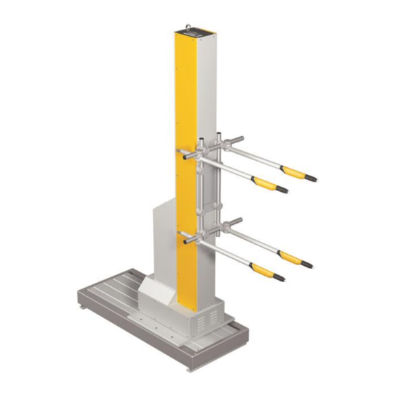
Rev. 01 11/22 Product description Intended use The ZA08 axis serves exclusively to move vertically powder applicators in automatic coating equipment. fig. 1 Observance of the operating, service and maintenance instructions specified by the manufacturer is also part of conformity of use. This... -
Page 16: Utilization
Rev. 01 11/22 Utilization The ZA08 type axis is used as the basis for all stages of automation, from a simple vertical stroke to complex, multi-dimensional processes. Depending on the design of the applicators, this unit may be used with all types of powder coating. - Page 17 To ensure that the reciprocator cannot become a hazard during normal operation, the axes are shielded by a protective fence that is 2.3 m high. The fence has doors that are released by the control unit to allow authorized technical personnel access to the axes. Product description • 17 ZA08...
-
Page 18: Schematic Presentation
Mobile version available – IP54 protection type – 4 standard stroke heights available: 1.3 m / 1.8 m / 2.3 m / 2.8 m – Intermediate and larger sizes available in steps of 250 mm 18 • Product description ZA08... -
Page 19: Expansion With Additional Axes Of Motion
Rev. 01 11/22 Expansion with additional axes of motion The vertical axis can be equipped with additional axes to expand its functionality. Fig. 4: Movement axes definition Product description • 19 ZA08... -
Page 20: Frequency Converter (Power Unit)
The frequency converter in the reciprocator is installed for power regulation. The parameters of this device are already adjusted to the Gema specific values and therefore may not be changed no more! All stroke/travel, speed, etc. settings can be made on the OptiMove control unit. -
Page 21: Technical Data
Rev. 01 11/22 Technical Data Versions The vertical axis is available, depending on operational area, in four versions with different standard stroke heights. ZA08-13 ZA08-18 ZA08-23 ZA08-28 Reciprocator height 2.385 m 2.885 m 3.385 m 3.885 m – H up to 1.3 up to 1.8... -
Page 22: Dimensions
Rev. 01 11/22 Dimensions fig. 6: Dimensions Sound pressure level ZA08 Normal operation < 60 dB(A) The sound pressure level was measured while the unit was in operation; measurements were taken at the most frequent operator positions and at a height of 1.7 m from the ground. -
Page 23: Rating Plate
Rev. 01 11/22 Rating plate fig. 7: Rating plate Fields with a gray background contain contract-specific data! Product description • 23 ZA08... - Page 24 Rev. 01 11/22 24 • Product description ZA08...
-
Page 25: Assembly / Connection
► In order to enter the inner area, the door interlocks must be released by the control unit. This release signal may only be activated by technical personnel. ► Except for normal operation, all other operating modes must be set up by an authorized technical representative. Assembly / Connection • 25 ZA08... -
Page 26: Grounding Of The Axis
► Ground all metal parts of the axis according to the general, local safety regulations. ► Check regularly the grounding of the axis. At least one corresponding connection point at the axis is reserved for the potential equalization. fig. 8: Potential equalization – connection point 26 • Assembly / Connection ZA08... -
Page 27: Electrical Connections / Cable Connections
Rev. 01 11/22 Electrical connections / cable connections Fig. 9: Connections: OptiMove control unit <–> vertical axis Close the unused connections with the provided dust protection caps! Assembly / Connection • 27 ZA08... - Page 28 Rev. 01 11/22 28 • Assembly / Connection ZA08...
-
Page 29: Start-Up
The stroke length of the reciprocator must be in the range of the booth opening (collision danger!). – Make sure that the automatic guns cannot collide with the work pieces (incorrectly adjusted stroke parameters on the reciprocator control unit). Start-up • 29 ZA08... -
Page 30: Reference Point
ATTENTION Damages to the booth, to the gun holders etc. Reference point incorrectly set ► Set the reference point before the first start-up! ► Consider the lower edge of the gun slot! 30 • Start-up ZA08... -
Page 31: Setting The Reference Point
► Fit the mechanical stop to the gun slots because the axis moves up to 25 mm below the control’s zero point, when referencing! The position of the upper and the lower stop plate is set by a Gema service engineer when the reciprocator is assembled. -
Page 32: Setting The Lower Mechanical Stop
Refit the boarding/side panels After the adjustment of the mechanical stops, check the system parameter for the upper stop on the axis control unit! The value must not be larger than the maximum stroke possible between the stops! 32 • Start-up ZA08... -
Page 33: Operation
255 programs – change the program number – directly modify the running program – acknowledge the error message – input the system parameters – etc. For further information, see the corresponding operating manual! Operation • 33 ZA08... - Page 34 Rev. 01 11/22 34 • Operation ZA08...
-
Page 35: Decommissioning / Storage
Requirements on personnel carrying out the work All work should be carried out only by authorized technical personnel. Storage conditions Hazard notes There is no danger to personnel or the environment if the unit is stored properly. Decommissioning / Storage • 35 ZA08... -
Page 36: Type Of Storage
– Unplug the ground cable Cleaning The running surfaces of reciprocators must be thoroughly cleaned. Preservation The cleaned running surfaces of the column on reciprocators must be preserved with a suitable corrosion inhibitor (oiled). 36 • Decommissioning / Storage ZA08... -
Page 37: Maintenance During Storage
Rev. 01 11/22 Maintenance during storage Maintenance schedule No maintenance schedule is necessary. Maintenance works During long-term storage, periodically perform a visual check for corrosion. Decommissioning / Storage • 37 ZA08... - Page 38 Rev. 01 11/22 38 • Decommissioning / Storage ZA08...
-
Page 39: Maintenance / Repairs
The axis was designed to operate with a minimum of maintenance. The motor gear box is self-lubricating and maintenance-free. Regular maintenance and inspection of the axis increases the working reliability and avoids damages, repair downtimes etc.! Maintenance / Repairs • 39 ZA08... -
Page 40: Maintenance Schedule
Therefore, clean the drive unit from time to time (with a vacuum cleaner etc.). If the drive unit gearbox has to be changed for any reason, the complete unit has to be replaced! 40 • Maintenance / Repairs ZA08... -
Page 41: Replacing The Drive Unit
Note the position of the clamp plate on the drive belt holder, because it must be fitted in approximately the same position during assembly. Loosen the grub screw on the clamp ring in front of the flange bearing Maintenance / Repairs • 41 ZA08... -
Page 42: Toothed Belt
– Switch on the axis and check the carriage for quiet running. Check the toothed belt for elongation or wear (noisy running, strong vibration of the belt when reversing the direction of travel) 42 • Maintenance / Repairs ZA08... -
Page 43: Replacing The Toothed Belt
Remove the service cover on the base Let the Z carriage slowly run up and down the column a few times, to see if the drive belt does not ride up on the toothed wheel Load the Z carriage Maintenance / Repairs • 43 ZA08... - Page 44 Enter the toothed belt parameters – Two parameters must be entered for each axis type: Axle spacing Length-related mass Type [kg/m] [mm] ZA08-13 2156 ZA08-18 2656 0.2240 ZA08-23 3156 ZA08-28 3656 Release the motor brake manually, let the Z carriage move down...
-
Page 45: Toothed Wheel
– Let the Z carriage slowly run up and down the column a few times, to see if the drive belt must be tensioned more (see chapter "Tensioning the drive belt") Maintenance / Repairs • 45 ZA08... -
Page 46: Rollers - Z Carriage
Tighten the roller axle bolt (30) and the nut (34) Tightening torque: 50 Nm Tighten the grub screw (33) and secure it Fit the panels again and fasten them firmly The Z carriage should run evenly and quietly again! 46 • Maintenance / Repairs ZA08... -
Page 47: Frequency Converter Maintenance
► After switching off the power supply, wait at least 10 min. before working on the equipment, because the internal condensers need this time for discharging! ► Verify that the parts are deenergized by means of a voltmeter! Maintenance / Repairs • 47 ZA08... - Page 48 Rev. 01 11/22 48 • Maintenance / Repairs ZA08...
-
Page 49: Fault Clearance
Cracking noise rollers tightened too adjust the counter during operation strong rollers without clearance, ensure the correct tightening torque Fault clearance • 49 ZA08... - Page 50 The Z carriage runs control unit defective repair or replace into the upper stop maximum upper set correctly stroke limit incorrectly set 50 • Fault clearance ZA08...
-
Page 51: Disposal
Requirements on personnel carrying out the work The disposal of the product is to be carried out by the owner or operator. When disposing of components that are not manufactured by Gema, the instructions in the respective third-party manufacturer’s documentation must be observed. -
Page 52: Materials
Disconnect the mains supply, supply cables and additional units. Remove all product covers. Drain all existing lubricant supplies and dispose of accordingly. The product is now prepared for disassembly. The instructions in the third-party manufacturer’s documentation must be followed! 52 • Disposal ZA08... -
Page 53: Spare Parts List
When using the spare parts from other manufacturers the explosion protection is no longer guaranteed. If any damage is caused by this use all warrantee claims become invalid! ► Only original Gema spare parts should be used! Spare parts list • 53 ZA08... -
Page 54: Za08 - Complete
Rev. 01 11/22 ZA08 – complete Drive unit – complete, see also "Drive unit (complete)" Hexagon screw – M6x12 mm 1005 774 Cable lead-through – Ø 50 mm, 5+4 1004 006 Electrical module, see "Electrical module" Electrical module for XT/ YT axis, see separate XT or YT axis spare parts list Z carriage –... -
Page 55: Za08 - Complete
Rev. 01 11/22 ZA08 – complete Fig. 20: ZA08 – complete Spare parts list • 55 ZA08... -
Page 56: Toothed Wheel
Counter profile – 40/20x115 mm 386 774 Toothed wheel 386 600 Toothed belt 103 730#* ZA08-13 – L=4215 mm ZA08-18 – L=5215 mm ZA08-23 – L=6215 mm ZA08-28 – L=7215 mm Tensioning screw 386 596 Hexagon shakeproof screw – M6x12 mm... -
Page 57: Toothed Wheel
Rev. 01 11/22 Toothed wheel Fig. 21: Toothed wheel Spare parts list • 57 ZA08... -
Page 58: Z Carriage
Hexagon screw – M10x100 mm 214 213 Hexagon ribbed nut – M10, black 234 656 Hexagon grub screw – M5x16 mm 237 744 Hexagon nut – M5 205 150 # Wearing part Fig. 22: Z carriage 58 • Spare parts list ZA08... -
Page 59: Drive Unit (Complete)
386 464 Countersunk screw – M5x10 mm 214 671 Brake resistor – 100 Ohm/600 W, complete, incl. heat sink 800 397 Heat sink holder 1003 978 Cap screw 1002 965 Fig. 23: Drive unit (complete) Spare parts list • 59 ZA08... -
Page 60: Proximity Switch
Rubber buffer – Ø 35x40 mm, M8 211 664 Counter profile – 40/20x115 mm 386 774 Limit switch holder 1003 980 Hexagon ribbed nut – M10 234 656 Proximity switch 229 180 Fig. 24: Proximity switch 60 • Spare parts list ZA08... -
Page 61: Electrical Module
Rev. 01 11/22 Electrical module For all electric components, see also the Spare parts list in the enclosed wiring diagram! Frequency converter – for ZA08 (please indicate the axis serial number – see 1022 301 Rating plate) Adhesive seal strip... -
Page 62: Gun Holders
Rev. 01 11/22 Gun holders The following examples show a possible configuration of gun holders. – Please contact the Gema Service department in the case of special configurations! Gun holder for 1-4 guns Clamp element-half (order in pairs) 363 987 Cross clamping element –... -
Page 63: Gun Holder For 5-8 Guns
Tube – Ø 40x2000 mm 337 587 Tube – Ø 40 mm 103 314* Tube plug – Ø 40 mm, for pos. 7 236 381 * Please indicate length Fig. 27: Gun holder for 5-8 guns Spare parts list • 63 ZA08... -
Page 64: Gun Holder For 2X1-4 Guns
Tube – Ø 40x2000 mm 337 587 Tube – Ø 40 mm 103 314* Tube plug – Ø 40 mm, for pos. 7 236 381 * Please indicate length Fig. 28: Gun holder for 2x1-4 guns 64 • Spare parts list ZA08... -
Page 65: Vertical Gun Holder
Tube – Ø 40x2000 mm 337 587 Tube – Ø 40 mm 103 314* Tube plug – Ø 40 mm, for pos. 7 236 381 * Please indicate length Fig. 29: Vertical gun holder Spare parts list • 65 ZA08... -
Page 66: Gun Fixtures And Collision Protection
Collision protection for GA0x guns – Ø 30 mm (for ZA axis) 1001 199 Dummy piece for GA0x guns – complete, Ø 30 mm (for ZA axis) 1001 210 Fig. 30: Gun fixtures Fig. 31: Collision protection 66 • Spare parts list ZA08... - Page 67 Storage ............35 Electrical data ........... 21 Electrical module ..........61 Technical Data ..........21 Transport ............13 Fault clearance ..........49 Figure references in the text ......8 Versions ............21 Maintenance ............. 39 Spare parts list • 67 ZA08...
- Page 68 Rev. 01...
Need help?
Do you have a question about the ZA08 and is the answer not in the manual?
Questions and answers