
Related Manuals for Gema OptiMove CR09-C


Summary of Contents for Gema OptiMove CR09-C
- Page 1 Rev. 00 1024 602 Operating instructions and Spare parts list Axis control OptiMove CR09-C Translation of the original operating instructions...
- Page 2 To the best of our knowledge and belief, the information contained in this publication was correct and valid on the date of publication. Gema Switzerland GmbH makes no representations or warranties with respect to the contents or use of this publication, and reserves the right to revise this publication and make changes to its content without prior notice.
-
Page 3: Table Of Contents
Assembly / Connection Assembly guide ..................... 27 Connection instructions ..................28 Start-up Preparation for start-up ..................29 Basic conditions ..................29 Measures before initial start-up ............... 29 Electrical wiring and screening concept ........... 29 OptiMove CR09-C Table of contents • 3... - Page 4 Hazard notes ................... 57 Type of storage ..................57 Storage duration ..................57 Space requirements ................57 Physical requirements ................58 Maintenance during storage ................. 58 Maintenance schedule ................58 Maintenance works .................. 58 4 • Table of contents OptiMove CR09-C...
- Page 5 Materials ....................65 Disassembly of component groups ............... 65 Spare parts list Ordering spare parts ..................... 67 OptiMove CR09-C axis control unit............... 68 Front plate ......................69 Rear wall ....................... 70 Connecting material ....................71 Appendix – program table ..................72 OptiMove CR09-C Table of contents •...
-
Page 7: About These Instructions
General information This operating manual contains all the important information which you require for the working with the OptiMove CR09-C. It will safely guide you through the start-up process and give you references and tips for the optimal use when working with your powder coating system. -
Page 8: Structure Of Safety Notes
Possible consequences of the danger ► Prevention of the danger Software version This document describes the operation of the product OptiMove CR09-C with software version starting from 0.04.0. See chapter "Checking the software version" on page 55. Presentation of the contents Figure references in the text Figure references are used as cross references in the descriptive text. -
Page 9: Safety
If this product is to be used for other purposes or other substances outside of our guidelines then Gema Switzerland GmbH should be consulted. - Page 10 GmbH guarantee would no longer be valid. – We point out that the customer himself is responsible for the safe operation of the equipment. Gema Switzerland GmbH is in no way responsible for any resulting damage. For further information, see the more detailed Gema safety regulations.
- Page 11 ► Before working with the device, organize the required documents and read the section "Safety regulations". ► Work should only be carried out in accordance with the instructions of the relevant documents. ► Always work with the complete original document. OptiMove CR09-C Safety • 11...
- Page 12 Rev. 00 12/22 12 • Safety OptiMove CR09-C...
-
Page 13: Product Description
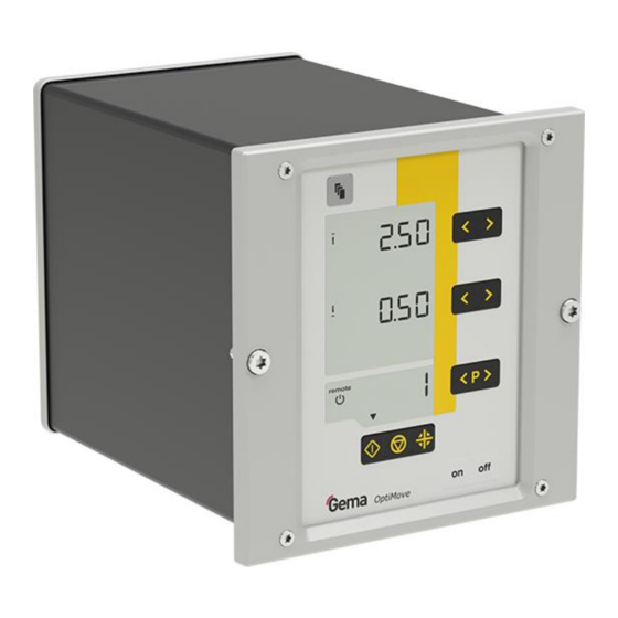
The axis control unit is designed exclusively for operating electrically driven axes in electrostatic powder coating equipments. Fig. 1: Axis control OptiMove CR09-C Observance of the operating, service and maintenance instructions specified by the manufacturer is also part of the intended use. This... -
Page 14: A Summary Of The Directives And Standards
BGI 764 / DGUV Trade Union information concerning health and Information safety during work (BGI) 209-052 Reasonably foreseeable misuse – Operation without the proper training – Use in connection with unauthorized devices or components 14 • Product description OptiMove CR09-C... -
Page 15: Technical Data
Rev. 00 12/22 Tec hnisc he D aten Technical Data Versions System integration via CAN bus OptiMove CR09-C The equipment designation is indicated on the type plate. Connectable axes OptiMove CR09-C connectable ZA08 XT11 ZA10 ATTENTION The axis control may only be used with the specified axis types! -
Page 16: Environmental Conditions
Rev. 00 12/22 Environmental conditions OptiMove CR09-C Utilization in the interior Height up to 2 000 m +5 °C - +40 °C Temperature range (+41 °F - +104 °F) Max. surface temperature +85 °C (+185 °F) 80 % for temperatures to 31 °C,... -
Page 17: Design And Function
The drive motor is equipped with an electrical retaining brake. The holding brake is activated if the axis control is disconnected from mains. OptiMove CR09-C Product description • 17... -
Page 18: Schematic Presentation
Rev. 00 12/22 Schematic presentation Fig. 4: Schematic presentation Axis control Motor cables Frequency converter Drive motor Pulse generator wiring Signal line Pulse generator Axis adapter 18 • Product description OptiMove CR09-C... -
Page 19: Operating Elements
Position of the axis while traveling or at a Level 1 standstill Level 2 – Axis upper position Level 3 – Speed upwards Level 4* – Dwell time Level 5* – Number of the following program – Parameter number – Parameter designation OptiMove CR09-C Product description • 19... - Page 20 Display background illumination (0-8) Remote operation mode, no local operation possible S12 remote – Remote operation mode is used as keyboard lock, reduced operation is possible Axis is running / not running S15-17 Displays the axis status 20 • Product description OptiMove CR09-C...
- Page 21 Input keys for desired values and system T1-T4 parameters Switch between display levels T5-T6 Program change Start axis Stop axis – Press and hold 5 seconds = system parameter Start reference point travel T11/T12 Power switch On/Off OptiMove CR09-C Product description • 21...
-
Page 22: Connections - Rear Side
Rev. 00 12/22 Connections – rear side Fig. 7: Connections – rear side (OptiMove CR09-C) 2.1 Power supply 2.4 DigitalBus parallel interface 2.2 Axis power supply 2.5 CAN bus input 2.3 Axis control signals 2.6 CAN bus output The cable connections have different plugs and cannot be wrongly connected on assembly. -
Page 23: Pin Assignment
GND frequency converter 24 V frequency converter frequency converter error RPM desired value Motor right running (UP) Motor left running (DOWN) Reserve Reserve 24 VDC OptiMove Motor brake Proximity switch Reserve GND OptiMove Enclosure – shield OptiMove CR09-C Product description • 23... -
Page 24: Scope Of Delivery
CAN low Enclosure – shield CAN OUT socket with 4 pins (2.6) Ground 24 VDC CAN high CAN low Enclosure – shield Scope of delivery – Mains cable – Quick-start guide and operating manual 24 • Product description OptiMove CR09-C... -
Page 25: Operating Modes
This is displayed on the operating panel by lighting-up of the remote symbol. Only a limited operation is possible by the operating panel, namely: – Start, stop, referencing axes OptiMove CR09-C Product description • 25... - Page 26 Rev. 00 12/22 – Input mode/display mode selection (desired values and actual values visualization) – Error messages acknowledgement 26 • Product description OptiMove CR09-C...
-
Page 27: Assembly / Connection
Rev. 00 12/22 Assembly / Connection Assembly guide The axis control unit is mounted into place using 2 M6 screws on the front side. Please contact Gema for other installation possibilities. Fig. 8 OptiMove CR09-C Assembly / Connection • 27... -
Page 28: Connection Instructions
The axis control unit is supplied ready for use by the manufacturer. Just a few cables must be connected. (See chapter "Pin assignment" on page 23.) Close the unused connections with the provided dust protection caps! CR09-C ZA08 Fig. 9: 28 • Assembly / Connection OptiMove CR09-C... -
Page 29: Start-Up
– Connect the control unit to the EMERGENCY STOP power circuit – Assembly and fitting of electric devices may only be done by an electrics specialist! OptiMove CR09-C Start-up • 29... -
Page 30: System Parameters
Turn on the axis control unit with the ON key Hold key down for 5 seconds – The display switches to the following level: – The system parameter number is shown in the display A1 with a P placed in front 30 • Start-up OptiMove CR09-C... - Page 31 HArd reference point" on page 44.) 0: 20 kbit/s 1: 50 kbit/s 2: 100 kbit/s 3: 125 kbit/s CAN Baud rate bAUd 4: 250 kbit/s 5: 500 kbit/s 6: 800 kbit/s 7: 1 Mbit/s 1000 OptiMove CR09-C Start-up • 31...
- Page 32 The display switches to the standard level System parameter P01 – setting the upper stroke limit If the axis control unit operates with a Gema axis, all system parameters are already set to the values for this axis. The only system parameter to be set is the upper stroke limit.
- Page 33 Rev. 00 12/22 Parameter value Level of detail of reports no messages few details all messages Selecting a parameter value above 4 may affect timing response performance. OptiMove CR09-C Start-up • 33...
-
Page 34: Can Bus
All desired values – All actual values – All control values – All system parameters (except Baud rate and CAN address) – All error messages – All special parameters such as software version etc. – Firmware update 34 • Start-up OptiMove CR09-C... -
Page 35: Hardware
127 Control units can be operated in a network. CAN bus cable – plug assignment Fig. 10: CAN bus cable Signal Color white +24 VDC black CAN H black CAN L black OptiMove CR09-C Start-up • 35... -
Page 36: Determining Device Address (Node-Id) And Baud Rate
The Baud rate is selected with 125 kbits as default. This setting permits a maximum cable length of approx. 500 m from the first to the last CAN bus user. If longer cables are used, select a lower Baud rate. 36 • Start-up OptiMove CR09-C... -
Page 37: Digitalbus Parallel Interface
3 bits. Control bits (Control) For inputs, there are 3 control bits available: – Axis Start - Start/Stop Axis Strobe - Data transfer activation – – Remote - Operating mode OptiMove CR09-C Start-up • 37... - Page 38 P2 = 4 X-GunClean Sequence Program 1 – 253 program Start Stop Dwell time Dwell time Program 254 – 255 Start Pause Start Stop By traveling to a reference point, the output always remains on "low"! 38 • Start-up OptiMove CR09-C...
-
Page 39: Command Table And Value Ranges
DATA STABLE Strobe signal Ts ≥ 20 ms Ts ≥ 100 ms Ts ≥ 20 ms Reading and processing OptiMove Composite error message Error low – correct transmission Composite error message Error high – incorrect transmission OptiMove CR09-C Start-up • 39... - Page 40 The Data bus is read in for data validation 3 times and the results compared, after every negative Strobe edge. If an error occurs, the digital output Error is set at high and the error message H30 is shown on display A5. 40 • Start-up OptiMove CR09-C...
-
Page 41: Software Description
Explanation: The simultaneous transmission of identical data to all OptiMove units only occurs on the negative edge of all strobe signals. Example of a PLC program: Program procedure diagram OptiMove CR09-C Start-up • 41... -
Page 42: Digital Connector Cd02 With Connection Designations
The exact plug assignment for the connection to the PLC is evident in the following illustration: 1-12 Strobe 1-12 1-12 Prog. active 1-8/13-20 D0-D7 1: GND 13-24 Start axis 13-24 Remote/Man. 13-24 Error/not 9-11/21-23 A0-A2 2: +24 VDC referenced 3: PE Unit no. Fig. 12: Digital Connector CD02 42 • Start-up OptiMove CR09-C... -
Page 43: Operation
Switch on/off the axis control unit Push the button – When the device is switched on, the standard level is displayed: Fig. 13: Standard level A1 = value for position A3 = value for speed A5 = Program number OptiMove CR09-C Operation • 43... -
Page 44: Travel To Reference Point
Switch on the axis control unit (see also "Switch on/off the axis control unit") If necessary, change to another program (see also "Program change") Press the key. – The axis is started, and the selected program is activated. 44 • Operation OptiMove CR09-C... -
Page 45: Program Change
In the Edit program mode, the input parameter values can be selected or changed. All program data must be determined! – Therefore, use the program tables in the appendix of this operating manual! The programs can be edited during operation and also at a standstill. OptiMove CR09-C Operation • 45... - Page 46 If a program is edited during operation, the axis terminates the old command, which is still in the memory, and takes over the new program values by the next cycle change! 46 • Operation OptiMove CR09-C...
-
Page 47: Axes Operating Modes
Axes operating modes General The axis control unit is used for the ZA08 Gema axis. To be ideally equipped for all conditions, the operating mode can be set in the system parameter mode P02. The following axes operating modes can be selected: –... -
Page 48: Editing/Setting
X axis. The prerequisite for the programming of sequence programs is that the system parameter P02 is already set correctly P02=2. – See also "System parameters" on page 30. 48 • Axes operating modes OptiMove CR09-C... -
Page 49: Structure Of A Program Step (Procedure Step)
Input the address of the following program on the display A1 using the keys 0 = no following program step 10. Press the key again, or press , in order to exit the Editing mode OptiMove CR09-C Axes operating modes • 49... -
Page 50: Programming Example - Positioning
Program no. 1 Display Input value 1.00 m 0.20 m/s Programming example – pendulum movements Program no. 1 Program no. 2 Display Input value Input value 0.10 m 1.80 m 0.20 m/s 0.30 m/s 50 • Axes operating modes OptiMove CR09-C... -
Page 51: Programming Example With Path-Time Diagram
Only a limited operation is possible by the operating panel, namely: – Referencing axes – Program editing when axis is moving – Program change when axis is moving OptiMove CR09-C Axes operating modes • 51... -
Page 52: Sequence Program X_Gunclean
Press the key at the same time. – The triangle above the key flashes to indicate that the Setup mode is active. Press in the display area A1, in order to start the axis 52 • Axes operating modes OptiMove CR09-C... -
Page 53: Setup Mode By Keyboard (Sequence Program)
– The new position of the first program step is programmed Select next program step using keys. – The display A5 shows the program number Repeat the steps 2-4 for further program steps OptiMove CR09-C Axes operating modes • 53... -
Page 54: Memory Reset
Operating type P03: Acceleration [m/s²] 1.50 P04: Max. speed [m/s] 0.60 P05: Open loop gain P06: Adaptation of incremental pulse generator P07: Holding brake delay time P08: Communication P09: Keyboard lock P10: Referencing mode 54 • Axes operating modes OptiMove CR09-C... -
Page 55: Checking The Software Version
The switch-on hour counter (total time in days of switch-on time) is shown in the display (e.g. 35.5 days = 852 h). The status display is shown as long as the keys are held. The hour counter can't be reset! OptiMove CR09-C Axes operating modes • 55... - Page 56 Rev. 00 12/22 56 • Axes operating modes OptiMove CR09-C...
-
Page 57: Decommissioning / Storage
If the physical conditions are maintained, the unit can be stored indefinitely. Space requirements The space requirements correspond to the size of the product. There are no special requirements concerning distance to neighboring equipment. OptiMove CR09-C Decommissioning / Storage • 57... -
Page 58: Physical Requirements
Storage must be inside a dry building at a temperature between +5 and +50 °C. Do not expose to direct sunlight! Maintenance during storage Maintenance schedule No maintenance schedule is necessary. Maintenance works During long-term storage, periodically perform a visual check. 58 • Decommissioning / Storage OptiMove CR09-C... -
Page 59: Maintenance / Repairs
Repair work In the event of malfunctions or faults, the product must be checked and repaired at an authorized Gema service location. The repairs must only be performed by an authorized specialist. Improper interventions can result in serious danger for user or the... - Page 60 Rev. 00 12/22 60 • Maintenance / Repairs OptiMove CR09-C...
-
Page 61: Fault Clearance
The error diagnosis codes (help codes) are shown in red on the A5 display. The help codes are stored in an error list in the order of their appearance. Each error in the list must be individually acknowledged with the keys T5 or T6. OptiMove CR09-C Fault clearance • 61... - Page 62 Store axis position, current program number and axis status Stop the system EEPROM content invalid EEPROM error Restart the control unit, otherwise contact a Gema service center TIMOUT during EEPROM EEPROM error Restart the control unit, writing otherwise contact a Gema...
- Page 63 1 and 127 Frequency converter Error message from the Axis is stopped Restart the axis, otherwise frequency converter contact a Gema service center Warning message from the Axis is stopped Restart the axis, otherwise frequency converter contact a Gema service...
- Page 64 Rev. 00 12/22 Code Description Criteria Remedy Overtemperature frequency Axis is stopped converter Heat sink temperature or frequency converter internal temperature too high 64 • Fault clearance OptiMove CR09-C...
-
Page 65: Disposal
Requirements on personnel carrying out the work The disposal of the product is to be carried out by the owner or operator. When disposing of components that are not manufactured by Gema, the instructions in the respective manufacturer’s documentation must be observed. - Page 66 Rev. 00 12/22 66 • Disposal OptiMove CR09-C...
-
Page 67: Spare Parts List
When using the spare parts from other manufacturers the explosion protection is no longer guaranteed. If any damage is caused by this use all warrantee claims become invalid! ► Only original Gema spare parts should be used! OptiMove CR09-C Spare parts list • 67... -
Page 68: Optimove Cr09-C Axis Control Unit
Rev. 00 12/22 OptiMove CR09-C axis control unit OptiMove CR09-C Axis control unit – complete 1022 202 Front plate – complete, see corresponding spare parts list Enclosure Backplate – complete, see corresponding spare parts list Fig. 14 68 • Spare parts list... -
Page 69: Front Plate
Washer – Ø 3.2/7x0.5 mm 201 944 Locknut – M3 262 498 Spacer sleeve – Ø 3.1/6x15 mm 261 548 Spacer sleeve – Ø 3.2/6x13 mm 1015 214 Fig. 15: OptiMove CR09-C – front plate OptiMove CR09-C Spare parts list • 69... -
Page 70: Rear Wall
CAN bus OUT connection – complete 1024 869 15.1 Socket – 4 pins, 1000 481 Drive supply connection – complete 1010 740 Power supply connection – complete 1010 741 Fig. 16: OptiMove CR09-C – Rear panel 70 • Spare parts list OptiMove CR09-C... -
Page 71: Connecting Material
Digital cable 19 pins – 5,50 m 1000 935 Digital cable 19 pins – 6,50 m 1000 936 Signal cable for ZAxx – L=20 m 1000 281 * Please indicate length Fig. 17: OptiMove CR09-C – connections OptiMove CR09-C Spare parts list • 71... -
Page 72: Appendix - Program Table
Rev. 00 12/22 Appendix – program table 72 • Spare parts list OptiMove CR09-C... - Page 73 Rev. 00 12/22 X position OptiMove CR09-C Spare parts list • 73...
- Page 74 Rev. 00 12/22 74 • Spare parts list OptiMove CR09-C...
- Page 75 Rev. 00 12/22 OptiMove CR09-C Spare parts list • 75...
- Page 77 Guidelines, European ........14 Start-up ............29 Storage ............57 Storage conditions ........... 57 Input keys and switches ........21 Stroke limit Intended use ............ 13 Upper ............32 Log messages ..........32 Versions ............15 OptiMove CR09-C Spare parts list • 77...
- Page 78 Rev. 00...
Need help?
Do you have a question about the OptiMove CR09-C and is the answer not in the manual?
Questions and answers