Table of Contents
Advertisement
Quick Links
User Manual PISA-M
1
Intended Use.......................................................................................................................................................................
2
Factory Settings...................................................................................................................................................................
3
Front Side and User Elements...........................................................................................................................................
4
Output Channel Status LEDs..............................................................................................................................................
5
Turn Output Channels ON or OFF.....................................................................................................................................
6
Check Current Tripping Setpoint of Each Output Channel.............................................................................................
7
Set Current Tripping Setpoint of Each Output Channel.................................................................................................
8
Set Tripping Characteristic of the Output Channels........................................................................................................
9
Change Power Supply Overload Protection.....................................................................................................................
10 Set Button Reaction Style..................................................................................................................................................
11 Reset Tripped Output Channels........................................................................................................................................ 10
11.1
Remotely Reset via Control Input.......................................................................................................................... 10
11.2
Manually Reset at Front Side User Elements........................................................................................................ 10
12 Select Communication Mode............................................................................................................................................. 11
PISA-M User Manual:
Jun. 2024 / Rev. 1.1
www.pulspower.com
2
2
3
4
5
5
6
7
8
9
1 / 12
Advertisement
Table of Contents

Related Manuals for Puls PISA-M Series


Summary of Contents for Puls PISA-M Series
-
Page 1: Table Of Contents
User Manual PISA-M Intended Use..................................Factory Settings................................... Front Side and User Elements............................Output Channel Status LEDs.............................. Turn Output Channels ON or OFF............................. Check Current Tripping Setpoint of Each Output Channel..................... Set Current Tripping Setpoint of Each Output Channel....................Set Tripping Characteristic of the Output Channels......................Change Power Supply Overload Protection........................ -
Page 2: Intended Use
Intended Use This user manual offers instructions on how to use the local user interface to configure the PISA-M electronic circuit breaker. Configurable product properties • Current tripping setpoint independent for each output channel (Adjustable only on the PISA-M-4ADJ model. All PISA-M-40x versions have fixed current tripping setpoints) •... -
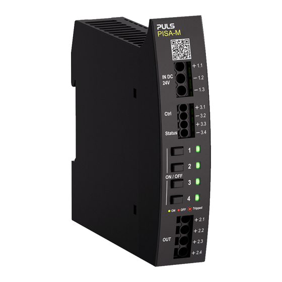
Page 3: Front Side And User Elements
Front Side and User Elements Input Terminals Identical poles are internally connected. (+) Input 12 - 24V / 20A (-) Input (-) Input Output Terminals (+) Output Channel 1 (+) Output Channel 2 (+) Output Channel 3 (+) Output Channel 4 Control Signal Input (+) Signal input positive pole (-) Signal input negative (return) pole... -
Page 4: Output Channel Status Leds
Output Channel Status LEDs The device front shows four LEDs – one per output channel. The LEDs indicate the status of each output channel. Green: Output channel ON Yellow: Output channel overload – prewarning before channel is triggered Red: Output channel turned OFF (manually or remotely) Red (flashing): Output channel tripped due to overload of this channel Red (double-flashing):... -
Page 5: Turn Output Channels On Or Off
Turn Output Channels ON or OFF Each output channel can be switched ON and OFF individually. The required duration of button press can be configured, see chapter 10 “Button Reaction Style”. → • Output channel is ON LED lights up green →... -
Page 6: Set Current Tripping Setpoint Of Each Output Channel
Set Current Tripping Setpoint of Each Output Channel • Only adjustable on PISA-M-4ADJ • All other PISA-M-40x versions come with four fixed output channels which cannot be adjusted. • The device will exit setting mode automatically after 10 s inactivity. The PISA-M-4ADJ allows individual adjustment of the tripping current of each output channel. -
Page 7: Set Tripping Characteristic Of The Output Channels
Set Tripping Characteristic of the Output Channels • The tripping characteristics can be uniformly configured as slow or fast for all output channels on all PISA-M versions. • The device will exit setting mode automatically after inactivity. Press CCB1 CCB3 simultaneously for ... -
Page 8: Change Power Supply Overload Protection
Change Power Supply Overload Protection The PISA-M offers a Power Supply Overload Protection to avoid voltage dips caused by overloaded output channels. To ensure high flexibility for different types of loads, the sensitivity of the Power Supply Overload Protection can be configured. -
Page 9: Set Button Reaction Style
10. Set Button Reaction Style • Affects all Channel Control Buttons. • The device will exit setting mode automatically after inactivity. The required duration of button press to turn an output channel ON or OFF can be configured. standard mode an output channel is switched ON or OFF by pressing the related CCB for long press mode an output channel is switched ON or OFF by pressing the related CCB for... -
Page 10: Reset Tripped Output Channels
11. Reset Tripped Output Channels 11.1. Remotely Reset via Control Input Tripped output channels can be reset via the control input pin 3.3 (+) and 3.4 (-) once the root-cause of the tripped output channel has been resolved. To reset, a voltage between 10-30 Vdc must be applied to the control input for ≥ 1 s. •... -
Page 11: Select Communication Mode
12. Select Communication Mode The device will exit setting mode automatically after inactivity. The device is equipped with two signal ports. Signal status output (pin 3.1 – 3.2) and signal control input (pin 3.3 – 3.4). These ports can be configured as follows: Tripping Alarm: Switch closes when at least one or more output channels are tripped. - Page 12 LED 4 green OK-Signal all other LEDs OFF Not assigned to application interface - LED 1 + LED 3 green reserved for update to all other LEDs OFF bus interface To select next communication mode press CCB2 CCB4 simultaneously for 50 ms within 4 ...
Need help?
Do you have a question about the PISA-M Series and is the answer not in the manual?
Questions and answers