Table of Contents
Advertisement
Quick Links
Advertisement
Table of Contents

Related Manuals for Autel Robotics Dragonfish Series


Summary of Contents for Autel Robotics Dragonfish Series
- Page 1 Dragonfish Standard Aircraft Flight Manual V2.1 2024.05...
- Page 2 Copyright This manual is copyrighted by Autel Robotics Co., Ltd. with all rights reserved. Without prior written authorization from the company, no person (or entity) may copy, scan, store, distribute, reproduce, sell, transfer, or modify any part or all of this manual in any form for personal use or use by others.
- Page 3 Tips: Quick tips to get the best possible experience. Read Before Your First Flight To ensure safe use of the Dragonfish Series Standard aircraft, Autel Robotics provides you with the following documents and relevant tutorial videos. Please scan the QR codes in this manual or use the provided links to access them.
- Page 4 Getting Tutorial videos, User Documents, and Relevant Software You can scan the QR codes below or visit the following links to access tutorial videos and user documents or download relevant software for the Dragonfish Series Standard aircraft: To watch tutorial videos, please visit: https://www.autelrobotics.com/videos/dragon-fish/...
- Page 5 Store the aircraft and its accessories out of the reach of children and pets. If you do not abide by the Safety Operation Guidelines, Autel Robotics shall not be responsible for any product damage or personal and property loss during use, and shall not provide any warranty service.
- Page 6 Autel Robotics guarantees users who purchase products through its official authorized channels that: Under normal use, the Autel Robotics products you purchase will be free from material and workmanship defects during the warranty period. If you can provide a valid purchase receipt, the warranty period of this product is calculated from the midnight of the next day after you receive the product.
-
Page 7: Table Of Contents
Table of Contents Chapter 1 Product Overview ........................11 Introduction ..........................11 What's In The Rugged Case ...................... 12 Product Acceptance Checklist ....................13 UAS Introduction ......................... 15 Chapter 2 Flight Safety ..........................19 Legal Use Notice .......................... 19 Chinese Mainland ......................19 The U.S. - Page 8 Post-Flight Process ......................43 Chapter 3 Product Details ........................44 Aircraft ............................44 Aircraft Components ...................... 44 Aircraft Navigation Lights ....................46 Smart Battery ........................49 3.1.3.1 Checking the battery level ..................50 3.1.3.2 Charging the smart battery ..................50 3.1.3.3 Smart battery functions ..................
- Page 9 3.4.10.2 Status bar ......................... 89 3.4.10.3 Map interface ......................90 3.4.10.4 Camera interface....................93 3.4.10.5 Aircraft settings interface ..................98 3.4.10.6 Other interfaces ....................105 Chapter 4 Flight Operations ........................110 Pre-Flight Operations ....................... 110 Assembling the Aircraft ....................110 Turning the Aircraft on ....................
- Page 10 Post-Flight Gimbal Check ..................... 204 Chapter 5 Upgrades, Maintenance and Checklists ................ 206 Equipments Upgrade ....................... 206 Aircraft Maintenance ....................... 207 Troubleshooting Guide ......................209 Pre-Flight Manual Checklist ....................213 Post-Flight Manual Checklist ....................225 Appendix A Specification ........................229 A.1 Aircraft ............................
-
Page 11: Chapter 1 Product Overview
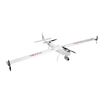
Chapter 1 Product Overview 11 Chapter 1 Product Overview Introduction The Dragonfish Standard (hereinafter referred to as the “aircraft”) is a small vertical takeoff and landing fixed-wing aircraft with a total weight of 7.5 kg (excluding the gimbal camera), a maximum payload of 1.5 kg, and a full battery life of up to 126 minutes. -
Page 12: What's In The Rugged Case
The protection level of the aircraft is not permanent and may experience varying degrees of failure as components age and wear. Regular maintenance of the aircraft is required according to Autel Robotics' requirements. The 4.5-hour battery life of the remote controller is measured with the screen brightness set to 50%. -
Page 13: Product Acceptance Checklist
After unboxing the product, please check whether the actual items match the items described in the following packing list and carefully inspect the appearance of the aircraft and all accessories. If anything missing or damage is found, please contact Autel Robotics After-Sales Support or authorized dealers promptly. - Page 14 Chapter 1 Product Overview 14 Airspeed Indicator Cover *the actual quantity is subject to the Battery purchased set. Charger + AC line Including AC line Propeller Blades Left and right: 2 pcs each Propeller Holder Front and rear: 1 pcs each The gimbal model is subject to the actual Gimbal Camera* set purchased, compatible: Z2, T3, T3H,...
-
Page 15: Uas Introduction
Chapter 1 Product Overview 15 UAS Introduction Before first flight, please perform a comprehensive inspection of the UAS to ensure that all components meet the following requirements. A complete UAS consists of three parts: the aircraft, the base station and the remote controller. The relevant requirements and explanations are as follows: ... - Page 16 Chapter 1 Product Overview 16 All the above components have passed Autel Robotics safety and compatibility tests, users can purchase and use accordingly. In case of adding any payload before flight, please evaluate the check the mounting weight reasonably.
- Page 17 Chapter 1 Product Overview 17 4.5.0 Clock System Software Files System Software Gallery 1.1.40030 System Software Chrome System Software 68.0.3440.70 Settings System Software Maxitools 2.01 System Software Google Pinyin System Software 4.5.2.193126728-arm64-v8a Input Android Keyboard System Software (AOSP) CX File Explorer System Software 1.4.2 ...
- Page 18 Chapter 1 Product Overview 18 When there's any prompt for updates, please follow the instructions to update accordingly to address any issues and to enjoy the new features. Users also have the option to temporarily pause updates; however, this won't affect the existing functions.
-
Page 19: Chapter 2 Flight Safety
The dragonfish standard series aircraft is a light unmanned drone, and the operation of this product by individuals under the age of 18 is prohibited by Autel Robotics. The pilots are required to obtain an UAV operation license according to the requirements of the Civil Aviation Administration. -
Page 20: Canada
This product is not a toy and should not be used by children under the age of 16. In the EU region, the dragonfish series aircraft belongs to the category of Level C3 UAV. When in use, it must comply with the operational restrictions of the A3 subcategory, specifically in urban environments: 1. -
Page 21: Other Countries And Regions
(https://www.easa.europa.eu/document-library/general-publications/drones-information- notices) According to the relevant laws and regulations in the EU, the dragonfish series aircraft is equipped with sensors (gimbal cameras) that can detect personal data. Users are required to register in compliance with the laws and regulations when using the aircraft. -
Page 22: Flight Environment Requirements
Keep the aircraft away from steel structures, iron ore mines, etc., to avoid interfering with the compass of the aircraft. Unless equipped with Autel robotics smart auto tracking antenna, do not take off and land aircraft on a moving platform, such as moving vehicles and ships. -
Page 23: Wireless Communication Requirements
Chapter 2 Flight Safety 23 Wireless Communication Requirements Stay away from areas with strong electromagnetic interference, such as radar stations, microwave stations, mobile communication base stations, drone interference devices, etc., and maintain a distance of at least 200 meters. ... - Page 24 Chapter 2 Flight Safety 24 1. Vertical takeoff using the multi-rotor mode switches to horizontal flight using the fixed-wing mode. 2. Horizontal flight using the fixed-wing mode switches to vertical descent using the multi-rotor mode. Departure routes (during takeoff) and arrival routes (during return) are involved during these two mode-switching processes.
- Page 25 Chapter 2 Flight Safety 25 Departure Route Attribute Altitude Type and Range Meaning MSL (above sea -410 meters to height which level) 9000 meters aircraft, after switching to fixed-wing mode, will adjust this altitude within departure Follow waypoint 1 (during waypoint hover, departing missions)
- Page 26 Chapter 2 Flight Safety 26 Fig 2-2 Arrival Route Table 2-2 Arrival Route Attribute Settings Arrival Route Attribute Altitude Type and Range Meaning Relative to takeoff -6000 point meters 6000 The altitude of the landing meters Landing point altitude point (also known as the home point) (Above -410 meters...
- Page 27 Chapter 2 Flight Safety 27 the arrival hover point in the arrival route. The default minimum distance between the arrival hovering point and the landing point is calculated as follows: [√3 times the minimum hover radius + 360 meters]. Users can drag the arrival hover point icon”...
-
Page 28: Terrain Obstacle Avoidance
Chapter 2 Flight Safety 28 Terrain Obstacle Avoidance The aircraft achieves terrain avoidance functionality through terrain maps, preventing collisions with terrain obstacles such as mountains during flight. The implementation involves real-time monitoring of the aircraft's altitude and the terrain's elevation. Based on the user-defined safety height, the aircraft adjusts its altitude to avoid potential collisions. - Page 29 Chapter 2 Flight Safety 29 waypoint missions or quick missions. They can also choose whether to enable terrain avoidance functionality during this process. Upon selecting terrain avoidance, if there is a conflict between the current route and the terrain, the system will automatically adjust the altitude of the flight segment based on the terrain height and the set safety height.
-
Page 30: Landing Protection Function
Chapter 2 Flight Safety 30 The aircraft's spiraling climb for obstacle avoidance has a circular path with its center located above the aircraft. The radius of this spiraling path is 100 meters. After the aircraft has successfully avoided the collision threat, it will return to its original altitude and continue executing the initial mission. - Page 31 Chapter 2 Flight Safety 31 The setting of the sticks is dependent on the stick mode chosen by the user. For specific details, please refer to Chapter 4, “4.1.7.3 Selecting stick mode“. When the aircraft reaches directly above the landing point, you can release the stick to hover the aircraft in the air.
-
Page 32: Rebuilding The C2 Link
Chapter 2 Flight Safety 32 Rebuilding the C2 Link To ensure the safety and controllability of flight behaviors, the Dragonfish Standard aircraft will stay in reconnection status and constantly attempt to reestablish a connection with the ground control station (remote controller) after losing the C2 link. In practice, this process is divided into the following stages: ... -
Page 33: Geofencing System
Chapter 2 Flight Safety 33 Geofencing system To ensure the safe and legal operation of the Dragonfish series aircraft, Autel robotics has developed an electronic fence system. This system allows for relevant constraints and limitations on the flight airspace of the aircraft during the flight. For details about geofencing system, please refer to “4.1.7.5 Creating a geofence and Unlocking a no-fly zone”... -
Page 34: Dual Control Function
Chapter 2 Flight Safety 34 During actual flights, the set flight altitude should not exceed the maximum height allowed by local laws and regulations. Dual Control Function The Dragonfish Standard aircraft supports a dual control function, meaning that in scenarios where the aircraft, the base station, and the remote controller are used in combination, one aircraft can simultaneously connect to two remote controllers (both connected to the base station). - Page 35 Chapter 2 Flight Safety 35 Scene Unable to control the aircraft's flight through virtual or physical buttons or sticks. Unable to control the aircraft's flight through commands: this includes not allowing editing, uploading, or executing missions, not permitting editing and issuing quick missions, and not allowing control of the aircraft's return. Not allowed to edit, set, or upload electronic fences.
-
Page 36: Aircraft Calibration
The aircraft compass is highly sensitive to strong magnetic field environments, which may result in deviations in magnetic heading. In severe cases, it could prevent the aircraft from taking off. If a compass malfunction prompt is displayed, please contact Autel robotics support or an authorized dealer for calibration. -
Page 37: Imu Calibration
If there is an abnormality in the IMU module after the power-on self-check, please contact Autel robotics support or an authorized dealer for assistance. Airspeed Sensor Calibration When the Autel Voyager Application displays a ”Airspeed failure. Please calibrate the airspeed meter. -
Page 38: Gimbal Auto Calibration
Chapter 2 Flight Safety 38 During the calibration process, the rear arms of the aircraft will flash yellow rapidly. Wait for the calibration to complete, and when the interface displays “Calibration Successful!”, the airspeed sensor calibration is successful. After successfully calibrating the airspeed sensor, remember to remove the airspeed tube protector promptly. -
Page 39: Emergency Propeller Stop
Lower the aircraft altitude and horizontal speed, then execute the emergency propeller stop function to minimize ground-related damage. After executing the emergency propeller stop in the air, it is crucial to contact Autel Robotics for a power inspection of the aircraft. -
Page 40: Mid-Flight Sensing
Chapter 2 Flight Safety 40 Mid-flight Sensing Automatic Dependent Surveillance-Broadcast (ADS-B) is a manned aircraft monitoring technology that allows a manned aircraft to determine its position using satellite navigation systems and broadcast the information regularly, making the aircraft trackable. Other aircraft can receive the information to achieve attitude awareness and autonomous avoidance. -
Page 41: Aircraft Inspection Monitoring System
Chapter 2 Flight Safety 41 The availability of the DRI system depends on the regulations in various countries and regions. Currently, the DRI system is not available in China. Aircraft Inspection Monitoring System The aircraft is equipped with a one-key self-check function and a safety monitoring function, which, together with manual checks before and after flight, constitute a comprehensive inspection monitoring system to ensure flight safety. -
Page 42: Basic Flight Process
Chapter 2 Flight Safety 42 Ensure that the surface of the power motors is clean, and both the power motors and servos rotate smoothly without any obstructions. Ensure that the gimbal camera is in the locked position with the aircraft's fuselage. ... -
Page 43: Post-Flight Process
Inspect the appearance of the aircraft, check whether there is any damage on the aircraft, such as dent. If there is serious damage, please contact Autel Robotics. Remove the batteries from the aircraft. For details about how to remove the battery, please refer to “4.1.1 Assembling the... -
Page 44: Chapter 3 Product Details
Chapter 3 Product Details 44 Chapter 3 Product Details Aircraft Aircraft Components Fig 3-1 Aircraft side top view Table 3-1 Description of the side top view of the aircraft Number Name Description The aircraft requires 2 batteries to provide the power Smart battery required for operation. - Page 45 Chapter 3 Product Details 45 Integrate a variety of sensors for stable shooting or Gimabal camera measurement while flying. The frequency matching button is located inside the rear battery compartment of the aircraft. Fig 3-2 Aircraft bottom view Table 3-2 Description of the side and upward view of the aircraft Number Name Description...
-
Page 46: Aircraft Navigation Lights
Chapter 3 Product Details 46 Located on the right wing of the aircraft, it is used for GNSS receiver GNSS positioning of the aircraft. Located on the right wing of the aircraft, it is connected to Airspeed tube the airspeed indicator and is used to measure the airspeed of the aircraft. - Page 47 Chapter 3 Product Details 47 Fig 3-3 Aircraft navigation light Table 3-3 Aircraft Navigation light description Number Name Description Located inside the rear end housing of the left wingtip Left Navigation light motor, it supports dual-color display in green and red. Located inside the rear end housing of the right wingtip Right Navigation light motor, it supports dual-color display in yellow and green.
- Page 48 Chapter 3 Product Details 48 Navigation light setting path: Tap “ ”>- “Navigation light” on the map interface or camera interface of the Autel Voyager App, follow the interface guidance to perform relevant operations. The flight light setting is only valid for a single power-on operation. The flight lights will return to the default flashing state after the aircraft is restarted.
-
Page 49: Smart Battery
Chapter 3 Product Details 49 Smart Battery The Dragonfish Standard aircraft comes standard with two DF6_12000_2310 smart batteries (hereafter referred to as smart battery) as the power battery. This battery is a rechargeable lithium-ion polymer (LiPo) battery and features high energy density and capacity. The smart battery can be charged with an DF_CHARGER battery charger. -
Page 50: Checking The Battery Level
Chapter 3 Product Details 50 3.1.3.1 Checking the battery level When the battery is turned off, press the power level check button for 1 second and then release it quickly to check the battery level. LED will indicate the current battery level, as shown below. Fig 3-5 Battery level indicator status (non-charging status) :Green is flashing :Green is normally on... - Page 51 Modifying the official smart battery or charging device provided by Autel Robotics is prohibited. Only use the battery and charging device provided by Autel Robotics. Autel Robotics is not responsible for any consequences, such as battery accidents and flight failure, caused by the use of third-party batteries or charging devices.
- Page 52 Chapter 3 Product Details 52 the battery temperature protection function will be activated, and the battery cannot be charged until its temperature drops below 40°C. It is recommended to fully charge the smart battery of the aircraft before the aircraft takes off.
-
Page 53: Smart Battery Functions
Chapter 3 Product Details 53 3.1.3.3 Smart battery functions The smart battery has the following functions: Battery Level Display The smart battery has a built-in battery level indicator, which shows the current battery level of the smart battery. Self-discharge protection for storage If the battery is stored in high temperature environment or it is not used for 6 days at a high battery level, the self-discharge protection will be activated. - Page 54 Chapter 3 Product Details 54 Overdischarge protection The battery will automatically disconnect the power output function when it is not used and completes the self-discharge procedure. This function is disabled in flight. Short-circuit protection The power supply will be disconnected if a short circuit is detected. ...
- Page 55 Chapter 3 Product Details 55 When the self-heating function of the smart battery is manually activated, the battery should have at least around 10% of remaining power for self-heating. When the smart battery is in the states of self-heating and heat preservation, the statuses of the battery level indicators are shown in the following table.
-
Page 56: Flight Control System
Chapter 3 Product Details 56 Before using the smart battery, please carefully read and strictly follow the requirements in this Manual, “Battery Safety Operation Guidelines”, and “Disclaimer”, and those on the battery's surface sticker. The user shall undertake all consequences if he/she fails to follow the usage requirements. -
Page 57: Flight Speed
Chapter 3 Product Details 57 and supports safety functions such as automatic return to home and loss of contact protection. Switch the remote controller to M position, and the user can manually control the aircraft to fly through the remote controller. Manual flight mode In this mode, the aircraft needs to be positioned through GNSS and supports safety functions such as automatic return to home and loss... -
Page 58: Intelligent Flight Function
Chapter 3 Product Details 58 Fixed-wing mode Flight speed: 17 m/s~30 m/s, ascending: 5 m/s, descending: 5 m/s. When flying manually in fixed-wing mode, be sure to pay attention to the surrounding environment and ensure that the flying airspace is open, unobstructed, and away from crowds, trees, and buildings. -
Page 59: Noise Description
Image Transmission Function The Dragonfish Standard aircraft is equipped with Autel Robotics self-developed image transmission technology. When used in combination with the Dragonfish base station (base station) and Dragonfish ground control station (remote controller), the image transmission distance can reach 30 kilometers. - Page 60 Chapter 3 Product Details 60 The data of transmission bit rate comes from test data. The data may be different due to different test environments and conditions. The image transmission distance is for reference only. Please always pay attention to the quality of the image transmission signal during actual use.
- Page 61 Chapter 3 Product Details 61 Table 3-13 Dragonfish Standard aircraft Global Frequency Bands Certified (Image Transmission) Certified Detaied Operating Frequency Bandwidth Countries & Frequency Regions BW=1.4MHz USA 900M 902-928MHz BW=10MHz Canada BW=20MHz BW=1.4MHz Chinese 2.4G 2400–2476MHz ...
-
Page 62: Gimbal Camera
Part number (EAN) 6924991123699 6924991127680 6924991124016 Part number (UPC) 889520203692 889520207683 889520204019 Manufacturer Autel Robotics Autel Robotics Autel Robotics information Controlling software Autel Voyager App Autel Voyager App Autel Voyager App Software version V1.0.0.0 or higher V1.0.0.0 or higher V2.0.80 or higher... - Page 63 Autel DG-T3 Autel DG-T3H Autel DG-L20T 6924991101 69249911022 (EAN) 6924991101802 6924991102274 8895200115 88952001202 (UPC) 889520011549 889520012010 Manufacturer Autel Autel Robotics Autel Robotics Autel Robotics information Robotics Maximum size 145×81×138 112.4×137.4×162 138×91×164 151×97×172 Gimbal Maximum weight of 702 g 806 g...
-
Page 64: Gimbal Structure
Chapter 3 Product Details 64 Gimbal Structure The Dragonfish Standard aircraft uses a three-axis stabilizing gimbal with a high-precision motor structure to ensure that the camera can capture stable images when the aircraft is in flight. Fig 3-8 Gimbal structure (DG-Z2 as an example) ... -
Page 65: Camera Layout
Chapter 3 Product Details 65 Used to control the range of left or right rotation of the gimbal on its own axis. Yaw axis motor mechanical range -320°~+320°, controllable movement range: -270°~+270°. Used to control the range of the gimbal rolling left or right. Roll axis motor The mechanical range is: -90°~+45°... -
Page 66: Camera Operation
Chapter 3 Product Details 66 1/2.5” CMOS, 8 million effective pixels, 20x continuous optical zoom, 12x digital zoom, 240x hybrid zoom. Wide-angle lens is used to capture a larger field of view within Wide-angle lens a shorter shooting distance. 1/2” CMOS, effective pixels 12 million. The infrared thermal imaging lens is used for temperature measurement and night vision. -
Page 67: Gimbal Mechanical Rotation Range
Chapter 3 Product Details 67 For the control operation of the remote controller, please refer to Chapter 3, “3.4.1 Remote Controller Components“. Control By Autel Voyager Application For the control and functions of the camera on the Autel Voyager App, please refer to Chapter “3.4.10.4 Camera interface“. -
Page 68: Replacing The Gimbal Camera
Frequent plugging and unplugging may cause poor contact between the aircraft and the gimbal camera due to wear and tear. Please use the gimbal camera model officially designated by Autel Robotics for replacement. Incompatible gimbal cameras can damage the aircraft. - Page 69 Chapter 3 Product Details 69 Fig 3-11 Install a gimbal camera on the aircraft After completing the installation of the gimbal camera according to the above steps, you can try to reversely rotate (do not press the gimbal unlock button) the gimbal locking ring. If the gimbal camera has been locked with the body's gimbal interface, the gimbal locking ring will not be able to be rotated.
-
Page 70: Installing A Tf Card On A Gimbal Camera
Chapter 3 Product Details 70 Fig 3-12 Remove the gimbal camera from the aircraft After removing the gimbal camera, be sure to install the lens protective cover and gimbal interface protective cover (or aircraft gimbal interface protective cover) of the gimbal camera in time to avoid damage during transportation and storage. -
Page 71: Base Station
Chapter 3 Product Details 71 If you want to shoot high-definition videos, it is recommended to use a Class 10, UHS-3 or higher TF card. Autel DG-series gimbal cameras support a maximum TF card size of 512GB. To prevent data loss, please turn off the power of the aircraft before removing the TF card. ... - Page 72 Chapter 3 Product Details 72 Table 3-19 Base station component description Name Description After the base station is powered on, the power range of the base station can be determined by the status of Power Indicator the indicator light. For details, please refer to “3.3.4 Checking the base station power“...
-
Page 73: Communication Frequency
Chapter 3 Product Details 73 Antenna feeder Used to connect the image transmission antenna interface feeder. Pallet mounting Used to install fixed base station tray. holes Communication Frequency The frequency band of dragonfish base Station meets the regulatory requirements around the world. - Page 74 Chapter 3 Product Details 74 5154 - 5246MHz BW=1.4MHz USA 5.2G 5157 - 5243MHz BW=10MHz Australia 5167 - 5233MHz BW=20MHz 5728 - 5826MHz BW=1.4MHz Chinese 5.8G 5733 - 5821MHz BW=10MHz Mainland 5738 - 5818MHz ...
-
Page 75: Turning The Base Station On/Off
Chapter 3 Product Details 75 modules is strictly prohibited. If flying in any countries not listed in the above table, please consult the local communication management authorities to ensure that the aircraft communication frequency bands comply with local regulatory requirements. ... -
Page 76: Charging The Base Station
AC power supply (100-240V ~ 50/60Hz). Fig 3-16 Charge the base station via base station charger Please use the charger officially provided by Autel Robotics to charge the base station. Using a third-party charger may damage the battery of the base station. -
Page 77: Remote Controller Components
Chapter 3 Product Details 77 When the controller is used with aircraft, its 5.8G data transmission distance is 1km and the image transmission range is 8-10 km; when the RC is used with base station and aircraft, it offers a maximum communication distance of 30 kilometers. ... - Page 78 Chapter 3 Product Details 78 Mode Switch A: Auto Mode;M: Manual Mode Button Controls the state of motion of the aircraft. The default stick mode is Mode 2. In this mode, you can use the sticks to control Sticks the ascent, descent, and heading of the aircraft. You can set the stick mode in the Application.
- Page 79 Chapter 3 Product Details 79 Table 3-24 Remote Controller Rear View Details Name Description Tripod Interface Used for attaching tripods. Fig 3-19 Remote Controller Top View Table 3-25 Remote Controller Top View Details Name Description Press to turn on/off the remote controller. Power button When the remote controller is on, quickly press the power button to switch between Screen On and Screen Off.
-
Page 80: Communication Frequency Bands
Chapter 3 Product Details 80 Communication Frequency Bands The image transmission frequency bands of Dragonfish base station comply with regulatory requirements worldwide. Please refer to the table below for the relevant certified frequency bands. After the aircraft is paired with the remote controller and base station, the frequency ... -
Page 81: Turning The Remote Controller On/Off
Chapter 3 Product Details 81 5733 - 5842MHz BW=10MHz Canada 5738 - 5839MHz BW=20MHz EU Australia Table 3-27 Global Frequency Bands Certified (Wi-Fi) Certified Operating Frequency Details Countries & Regions Chinese Mainland USA 2.4G 802.11b/g/n ... - Page 82 Chapter 3 Product Details 82 Fig 3-20 Turning the Remote Controller On When using a brand-new remote controller for the first time, please follow the on-screen instructions to complete the relevant setup. When the remote controller is on, quickly press the power button to switch between Screen On and Screen Off.
-
Page 83: Flight Control Mode
Chapter 3 Product Details 83 When the remote controller is on, you can press and hold the power button at the top of the remote controller for 10 seconds to forcibly turn it off. Flight Control Mode With the remote controller, users can control the aircraft in Auto mode or Manual mode. Refer “3.1.5 Flight Modes“... -
Page 84: Charging The Remote Controller
AC power supply (100-240 V~ 50/60 Hz). Fig 3-22 Use the remote controller charger to charge the remote controller Please use the official charger provided by Autel Robotics to charge the remote controller. Using third-party chargers may damage the battery of the remote controller. -
Page 85: Calibrating The Remote Controller
Chapter 3 Product Details 85 During flight, it is suggested to use the remote controller with base station to enhance the connection. When users operate the aircraft, make sure that the aircraft is in the place for the best communications. -
Page 86: Hdmi Screen Output
Autel Voyager Application Autel Voyager Application is an industrial flight software developed by Autel Robotics especially for the Dragonfish series vertical take-off and fixed-wing aircrafts, and is installed on the Dragonfish ground station (remote controller). The Autel Voyager Application integrates multiple professional functions, is simple to operate, and easy to get started. - Page 87 Chapter 3 Product Details 87 interface, wide-angle lens interface, infrared lens interface, and split-screen (infrared + zoom) interface. When the aircraft is equipped with different gimbal camera, the lens interface displaced in camera interface will vary as well. [Aircraft Settings]: Provides access to software and hardware functionality settings related ...
- Page 88 Chapter 3 Product Details 88 Fig 3-24 Interface layout (camera interface) Table 3-29 Interface layout description Layout/Icon Description Mainly displays flight status information and device status Status bar information of the aircraft, the base station, and the remote controller. Real-time display of the remaining battery level of the aircraft and Battery bar the estimated remaining flight time.
-
Page 89: Status Bar
Chapter 3 Product Details 89 Tap this icon to go to [Aircraft Settings] interface where you can set parameters on Autel Voyager Application, aircraft, remote controller and base station. Tap this icon to go to [New User Tutorials] or [Flight Records] interface. -
Page 90: Map Interface
Chapter 3 Product Details 90 When two remote controllers are connected to a base station at the same time, the current remote controller is the pilot role. When two remote controllers are connected to a base station at the same time, the current remote controller is the observer role. The current base station's working mode is fixed mode, and the Dragonfish base station only supports fixed mode. - Page 91 Chapter 3 Product Details 91 Fig 3-26 Map Interface Table 3-31 Map interface icon description Icon Description Tap this icon to view the specific alarm content when an alarm icon appears. Tap this icon to select the map layer as “Standard”, “Hybrid”, or “3D” in three display styles, and support managing marked points and downloading offline maps.
- Page 92 Chapter 3 Product Details 92 Tap this icon to measure the distance between two points on the map, supporting continuous marking for measurement. After editing and saving the route mission, tap this icon to perform a pre-flight check and then select to start the mission. Tap this icon to complete the pre-flight check and perform takeoff, and the aircraft will take off vertically and hover.
-
Page 93: Camera Interface
Chapter 3 Product Details 93 3.4.10.4 Camera interface On the map interface, tap the camera interface preview window at the lower left corner to enter the camera interface. Fig 3-27 Camera interface When the aircraft is equipped with different gimbal cameras, the lens interface displayed on the camera interface will also be different. - Page 94 Chapter 3 Product Details 94 Tap this icon to realize quick return-to-center of the gimbal, including “pitch horizontal return to center”, “horizontal return to center pitch down”, “horizontal return to center” and “pitch return to center”. Tap this icon to keep the gimbal pitch angle horizontal and the gimbal heading to follow the aircraft heading.
- Page 95 Chapter 3 Product Details 95 Tap this icon to turn on the area temperature measurement function, which can measure the temperature range of the specified area. Tap this icon to turn on the point temperature measurement function, which can measure the temperature of a specified point. Tap this icon to turn on the center point temperature measurement function, which can measure the temperature of the center point of the image transmission screen.
- Page 96 Chapter 3 Product Details 96 Save location: can be set to “Flash memory” or “SD card”. After setting, the captured image files will be stored in the corresponding location. Histogram: Enable or disable the histogram function. The histogram can show the distribution of pixels in the image captured by the camera, thereby reflecting the exposure of the image.
- Page 97 Chapter 3 Product Details 97 General settings: Grid: Can be set to “None”, “Grid”, “Grid + Diagonal”. Setting up a grid can help with composition when shooting. Center point: can be set to “None”, “Square (Without Center Point)”, “Square (With Center Point)”, “Cross”, “Circle (Without Center Point)”, “Circle (With Center Point)”.
-
Page 98: Aircraft Settings Interface
Chapter 3 Product Details 98 Grid: Can be set to “None”, “Grid”, “Grid + Diagonal”. Setting up a grid can help with composition when shooting. Center point: can be set to “None”, “Square (Without Center Point)”, “Square (With Center Point)”, “Cross”, “Circle (Without Center Point)”, “Circle (With Center Point)”. - Page 99 Chapter 3 Product Details 99 Fig 3-28 Aircraft settings interface 1 Fig 3-29 Aircraft settings interface 2...
- Page 100 Chapter 3 Product Details 100 Table 3-33 Setting items in aircraft interface Setting Entry Setting Item Work Mode: Can be set to “Fixed” or “Mobile”. Coordinate type: Can be set to “DMS”, “DD”, “UTM” or “MGRS”. Aircraft coordinate display: Turn on or off this function. ...
- Page 101 Chapter 3 Product Details 101 number of the front and rear batteries. Self Discharge Time: Set the battery self-discharge time to protect the battery. Intelligent Low Battery Return: This function can be turned on or off. Intelligent Low Battery: The remaining power after landing can be set between 15% and 50%.
- Page 102 Chapter 3 Product Details 102 UAV firmware: Displays the aircraft firmware version number and will give a prompt if there is an update. Wi-Fi Update: Displays the base station firmware version number, and will give a prompt if there is an update. ...
- Page 103 Chapter 3 Product Details 103 Projection Area Users can enable the projection area display function in the following two ways: Turn on the “Projection Area Display” or “Projection Center Coordinate Display” function in the “Projection area” column on the [Aircraft Settings] interface. ...
- Page 104 Chapter 3 Product Details 104 Fig 3-31 Projection area display is on Users can also clear the projected area on the map interface by: Turning off the projection area display function to clear the projection area. Tapping the “ ”...
-
Page 105: Other Interfaces
Chapter 3 Product Details 105 3.4.10.6 Other interfaces On the map interface or the status bar at the top of the camera interface of the Autel Voyager Application, tap the “ ” icon to access the [New User Tutorial] interface and [Flight Records] interface. - Page 106 Chapter 3 Product Details 106 synchronization. After logging into the Autel cloud account, flight records uploaded to the Autel cloud can be downloaded and synchronized to other remote controllers. Users can also download the flight records uploaded to the Autel cloud to the local for viewing. Fig 3-33 Flight records ...
- Page 107 Chapter 3 Product Details 107 needs to be connected to the network. In the camera interface of Autel Voyager Application, tap the “ ” icon to access the [Album] interface. Users can view, edit, or download images captured by the aircraft on the [Album] interface.
- Page 108 Chapter 3 Product Details 108 In the map interface of the Autel Voyager Application, tap the “ ” icon to access the [Mission Library] interface. The [Mission Library] interface contains all saved waypoint missions, polygon missions and geofences. Users can search, filter and edit saved missions through the mission library, which supports import, export and delete operations.
- Page 109 Chapter 3 Product Details 109 Currently importing/exporting files in KML format are supported. For a permanently effective geo-fence, “Permanently Valid” will be displayed on the geo- fence card; for a time-limited geo-fence, “To be effective + start effective time” will be displayed when it is not in effect, and “Effective + effective end time”...
-
Page 110: Chapter 4 Flight Operations
Chapter 4 Flight Operations 110 Chapter 4 Flight Operations This chapter introduces the flight operation procedures and cautions, as well as manual check lists. To ensure flight safety, please go through this chapter. Pre-Flight Operations Assembling the Aircraft During transportation, the aircraft needs to be disassembled into parts and placed in an industrial box. - Page 111 The wingtip propellers are installed by default before shipment. Generally, users do not need to install them. If you need to replace them, please contact Autel Robotics After-Sale department. The propellers on the front and rear fuselage of the aircraft are fastened with screws and are installed by default at the factory.
- Page 112 Chapter 4 Flight Operations 112 any lag or abnormal noise. Please use propellers provided by Autel Robotics. Propellers of different models cannot be mixed. Before replacing the propeller, make sure the power of the aircraft is turned off.
-
Page 113: Turning The Aircraft On
Chapter 4 Flight Operations 113 Remove the Smart Battery* Turn off the smart battery before removing the battery. Press and hold the unlock buttons on both sides of the smart battery and slowly pull out the battery. The unlock buttons of the smart battery are consumable parts. Please do not press them hard to avoid any possible damage to the internal structure of the battery. -
Page 114: Assembling The Base Station
Chapter 4 Flight Operations 114 Assembling the Base Station Before assembling the base station, please check whether the base station components are complete: Base station main body × 1, tripod × 1, base station tray × 1, image transmission antenna × 2, and antenna feeder ×... -
Page 115: Matching And Connection
Chapter 4 Flight Operations 115 a flight accident. Matching and Connection Matching and connection refers to building up linkage communication relation among the aircraft, the base station and the ground control station (the remote controller). It has two connection methods: 1. - Page 116 Chapter 4 Flight Operations 116 Fig 4-6 Matching and Connection Matching and Connection Procedures Image transmission matching between the base station and the aircraft Turn on the power of the base station and press the base station match button for 1 second. At this time, the match indicator light will flash green on and off at a frequency of 0.1 seconds/0.1 seconds.
- Page 117 Chapter 4 Flight Operations 117 Green light flashes on and off for 0.1 Image transmission normal seconds/ 2.0 seconds connection Green light flashes on and off for 2.0 Upgrade download data seconds/ 0.2 seconds Green light is always on Firmware upgrade in progress Remote controller connected to base station Wi-Fi ...
- Page 118 Chapter 4 Flight Operations 118 or connection failure due to the distance. Avoid synchronizing or connecting with other aircraft, RCs and base stations that are synchronizing or connecting at the same time, so as to avoid security risks caused by connection errors.
-
Page 119: Aircraft Activation
Chapter 4 Flight Operations 119 the rear of the aircraft, press release button below the battery, make sure indicator quickly flashing. Tap “I have completed the procedure above” on the Application interface, and then “Start connection”. After frequency matching ... -
Page 120: Installing The Remote Controller Lanyard
Make sure the remote controller is connected to the Internet before activation, otherwise the activation will fail. If activation fails, please contact Autel Robotics User Support for resolution. For frequency binding operations between the aircraft, remote controller, and base station, please refer to “4.1.4 Matching and... -
Page 121: Pre-Flight Inspection And Preparation
Chapter 4 Flight Operations 121 Fig 4-7 Install The Remote Controller Lanyard (As Required) Pre-Flight Inspection and Preparation To ensure flight safety and provide great flight experience to users, it is recommended that users should conduct pre-flight inspection and preparation before every flight. The pre-flight inspection includes inspections on the aircraft, components and the gimbal and the pre-flight preparation includes offline map download and caching, geofencing function, creating route missions and inspection monitoring system. - Page 122 Chapter 4 Flight Operations 122 Appearance Paint Inspection Examine the paint condition of airframe and installed components to ensure that there are no damages, obvious scratches, cracks, or peeling. Although non-extreme paint conditions will not seriously affect flight safety, they may reduce product performance and user experience. ...
- Page 123 Chapter 4 Flight Operations 123 Tightening Inspection Check the following components for tight installation to ensure that the fasteners are in place without missing, the installation is tight without looseness, and the components are firmly connected: Motor and blade connection: including the front and rear fuselage motors, blades, and left and right wingtip motors and blades.
-
Page 124: Pre-Flight Gimbal Check
4.1.7.2 Pre-flight gimbal check Dragonfish series aircrafts can carry a variety of industry application mounts to meet the needs of complex tasks, greatly improving the reuse value of the product. A comprehensive inspection of the gimbal camera is required before flight to ensure that it can meet task requirements. -
Page 125: Selecting Stick Mode
Chapter 4 Flight Operations 125 4.1.7.3 Selecting stick mode When using the remote controller to operate the aircraft, you need to know the current stick mode of the remote controller and fly with caution. Three stick modes are available, that is, Mode 1, Mode 2 (default), and Mode 3. ... - Page 126 Chapter 4 Flight Operations 126 Fig 4-9 Mode 2 Table 4-4 Mode 2 Details Stick Move Up/Down Move Left/Right Controls the ascent and descent Controls the heading of the Left Stick of the aircraft aircraft Controls forward Controls left right Right Stick backward movement of the movement of the aircraft...
- Page 127 Chapter 4 Flight Operations 127 Do not hand over the remote controller to persons who have not learned how to use the remote controller. If you are operating the aircraft for the first time, please keep the force gentle when moving the sticks until you are familiar with the operation.
- Page 128 Chapter 4 Flight Operations 128 4. When the stick returns to the center, the rotational angular speed of the aircraft is expected to be zero. 5. The larger the degree of the stick movement, the greater the rotational angular speed of the aircraft. Right Stick 1.
-
Page 129: Offline Map Download And Caching
Chapter 4 Flight Operations 129 When controlling the aircraft for landing, pull the throttle stick down to its lowest position. In this case, the aircraft will descend to an altitude of 1.0 meter above the ground, and then it will perform an assisted landing and automatically descend slowly. 4.1.7.4 Offline map download and caching The aircraft supports an offline map function, which allows users to assist in mission planning by pre-downloading map data without a network connection. -
Page 130: Creating A Geofence And Unlocking A No-Fly Zone
4.1.7.5 Creating a geofence and unlocking a no-fly zone To ensure the safe and legal operation of the Dragonfish series aircraft, Autel robotics has developed a geofencing system. This system allows for relevant constraints and limitations on the flight airspace of the aircraft during the flight. The geofencing system consists of two parts: Customized Electronic Fence and National No-Fly Zones. - Page 131 Chapter 4 Flight Operations 131 to automatically update legally restricted no-fly zone information and synchronize it with the aircraft. During the flight, relevant flight space restrictions will be displayed synchronously on the Autel Voyager Application to ensure the safe and legal operation of the aircraft. ...
- Page 132 Chapter 4 Flight Operations 132 Added to the geofencing system by users themselves. Geofence Flight restriction: The aircraft can fly within any geofence area but cannot fly outside that range. After users apply for the lifting of the ban (by signing a liability waiver or obtaining an official airspace authorization Authorized zone document), the aircraft can legally operate within the...
- Page 133 Chapter 4 Flight Operations 133 Fig 4-12 Buffer Zones Table 4-8 Flight buffer Zone Description Buffer Zone Type Buffer Zone Description When an unauthorized aircraft approaches within a range of 300 meters near the edge of a no-fly zone, the remote controller will issue an alert “The aircraft is close to the no-fly zone”.
- Page 134 Chapter 4 Flight Operations 134 If the aircraft is in the air, it can only move slowly inward within the buffer zone of the geofence until it enters the geofence area. It cannot fly outward to leave the geofence. When the aircraft is located outside the geofence, the remote controller will issue an alert “The aircraft is out of the geo- fence”.
- Page 135 Chapter 4 Flight Operations 135 Create a (customized) geofence Users can create a (customized) geofence accordingly. In the Autel Voyage Application, tap “ ” icon on the map interface, and then tap the “ ” icon to enter the “Editing Geo-fence” interface. Users can place a rectangular or circular area on the map interface and perform operations such as dragging, adjusting the radius (circular area), adding and dragging vertices (polygon area) to adjust the location and size of the area;...
- Page 136 Chapter 4 Flight Operations 136 Add a (customized) geofence When creating a (custom) geofence, users can add a polygon or circular area by tapping anywhere on the map interface. After placing the area, if it is a circular area, you can adjust the area size by stretching the radius adjustment points;...
- Page 137 Chapter 4 Flight Operations 137 “Geo-Fence” function switch. Import a geofence Besides creating a geofence, the user can also import a geofence into the RC. The aircraft supports the geofence import function, allowing users to obtain the restricted flight zone data file of their country or region and upload it to the flight control system of the aircraft.
- Page 138 Chapter 4 Flight Operations 138 displayed on the remote controller is consistent with the geo-fence information stored in the aircraft, the remote controller will update the geo-fence information to the aircraft under the following circumstances: 1. The remote controller is connected to the aircraft and the aircraft is on the ground, and the current latitude and longitude positioning information of the aircraft can be obtained.
- Page 139 Chapter 4 Flight Operations 139 Users can also enable the 'Flight allowed in no-fly zones' feature in the 'Safety' section of the remote controller settings (not available in China). After signing the disclaimer and obtaining clearance for national no-fly zones, the aircraft will remain cleared throughout the duration of this feature being enabled.
- Page 140 Chapter 4 Flight Operations 140 Before a mission route is uploaded, the ground control station will verify the relation between the route and geofence. If there is a conflict (such as the route approaching a no-fly zone, the route being located within a no-fly zone, or the route being located outside a geofence), the aircraft will not be able to take off along that route.
- Page 141 Chapter 4 Flight Operations 141 Fig 4-15 When the target point is outside the geofence Fig 4-16 When the target point is inside the No-fly zone...
-
Page 142: Creating A Route Mission
For details, please refer to mechanism part of geofencing system. 4.1.7.6 Creating a route mission Dragonfish Series Aircrafts support mission planning (waypoint mission and polygon mission) before flight, which can meet the requirements from users. Users can create a waypoint mission or a polygon mission. - Page 143 Chapter 4 Flight Operations 143 associated with the flight path executed by the aircraft by covering or specifying the flight segment. When the aircraft flies through the effective range of the specified observation area on the route, the gimbal will always face the center position of the observation area until it flies away from the effective range of the observation area.
- Page 144 Chapter 4 Flight Operations 144 Fig 4-18 Waypoint route procedures Add waypoints When creating a waypoint mission, users can add waypoints by tapping anywhere on the map interface, or after adding the first waypoint, they can tap the “ ”...
- Page 145 Chapter 4 Flight Operations 145 The setting of the landing point altitude will affect the landing speed control of the aircraft. When enabling the remote take-off and landing function, please fill it in according to the actual altitude. 2. Tap the “ ”...
- Page 146 Chapter 4 Flight Operations 146 difficult for the aircraft to decelerate. When the aircraft flies over the landing point, if the speed has not decelerated to zero, it may cause it to overshoot the landing point. The higher the wind speed, the farther it travels . ...
- Page 147 Chapter 4 Flight Operations 147 Supplementary instructions for waypoint altitude The waypoint altitude of each waypoint is the altitude when the aircraft leaves this waypoint. If the aircraft is limited by the climbing rate and fails to reach the altitude set for this waypoint when it arrives at this waypoint, the aircraft will hover and climb to the set waypoint altitude, then leave this waypoint and fly to the next waypoint.
- Page 148 Chapter 4 Flight Operations 148 Timed Orbit/Circular Orbit: used when the aircraft needs to hover at a certain waypoint to perform the corresponding task. The aircraft will complete the set hovering action at the waypoint according to the set hovering attributes (such as orbit parameters and turn radius). Then fly to the next waypoint.
- Page 149 Chapter 4 Flight Operations 149 Fig 4-21 The flight segment corresponding to the waypoint Supplementary descriptions for gimbal movements Gimbal Pitch Angle: When the aircraft enters the segment corresponding to the waypoint, it will automatically adjust the gimbal pitch angle to the set angle value. It is defined that 0° means the gimbal is facing forward horizontally, and -90°...
- Page 150 Chapter 4 Flight Operations 150 Fig 4-23 Description of gimbal relative heading angle The gimbal movement (gimbal pitch angle and gimbal relative heading angle) will only take effect once at the beginning of the flight segment corresponding to the waypoint. After entering the flight segment corresponding to the new waypoint, the aircraft will adjust the pitch angle and the relative heading angle of the gimbal once based on the gimbal action set for the new waypoint.
- Page 151 Chapter 4 Flight Operations 151 After entering the “Batch Edit Waypoints” window, you can modify the attributes of the selected waypoints in batches. The batch editing waypoint function supports the selection of all waypoints for batch editing, or only selects some waypoints for batch editing. Fig 4-24 “Batch Edit Waypoints”...
- Page 152 Chapter 4 Flight Operations 152 Select and drag the observation area on the map interface to quickly adjust its position on the map. After adding an observation area and associating it with the corresponding flight segment, you can execute the observation area waypoint mission. ...
- Page 153 Chapter 4 Flight Operations 153 When the observation area is not associated with a flight segment, if the aircraft flies within the radius of the observation area, the aircraft gimbal will always face the center point of the observation area; after leaving the observation area, the aircraft gimbal will return to the original flight segment settings angle.
- Page 154 Chapter 4 Flight Operations 154 Tap the “ ” icon in the small window at the upper right corner to re-edit the waypoint mission. After the aircraft performs pre-flight inspection, you can choose to tap the “ ” icon to take off and perform waypoint missions.
- Page 155 Chapter 4 Flight Operations 155 Application will automatically generate departure hovering points, arrival hovering points, and home point (the default one is the takeoff position of the aircraft). Polygon missions are mostly used in mission scenarios such as surveying and modeling. Before performing this mission, please plan your own reasonable emergency support measures (such as planning reasonable airspace, safe flight time periods, obtaining official authorization, etc.) to avoid abnormal flight situations that may cause collateral damage to...
- Page 156 Chapter 4 Flight Operations 156 Polygon vertex positions (identified by numbers). Add polygon regions and vertices When creating a polygon mission, users can tap anywhere on the map interface to add a polygon area (the default one is a rectangular area). After placing the area, tap the “ ”...
- Page 157 Chapter 4 Flight Operations 157 Please pay attention to the terrain drop, fill in the Reference Surface altitude according to the actual altitude of the surveying area, set the “Relative Reference Surface Flight Altitude” reasonably, and check whether the route elevation is safe before flying, otherwise there may be a risk of collision.
-
Page 158: Real-Time Monitoring And One-Key Self-Check
Chapter 4 Flight Operations 158 Arrival Altitude (m): It can be set to “Relative Landing Point” or “MSL”. Select “Relative Landing Point” to set the range from 40 to 2000 and select “MSL” to set the range from-410 to 9000. ... - Page 159 Chapter 4 Flight Operations 159 inspection monitoring system to ensure flight safety. Users can monitor the aircraft status in real-time through the Autel Voyager Application. Safety Monitoring The aircraft is equipped with various types and quantities of sensor devices, and advanced fault detection algorithms enable real-time monitoring of various states throughout the entire flight.
-
Page 160: Flight
A complete flight comprises takeoff, during-flight and landing. Takeoff Autel Dragonfish Series aircrafts provide different types of takeoff methods for users to choose accordingly, which include manual takeoff, one-key takeoff and mission takeoff. Before taking off, please do a pre-flight inspection to ensure that the aircraft is in a safe and flyable condition. -
Page 161: Manual Takeoff
Chapter 4 Flight Operations 161 4.2.1.1 Manual takeoff When choosing manual takeoff, users can conduct aircraft manual flight by taking following steps: Power on the aircraft, the base station and the remote controller and complete matching. For details about matching and connection, please refer to “4.1.4 Matching and Connection”. -
Page 162: One-Tap Takeoff
Chapter 4 Flight Operations 162 troubleshooting prompts on the Application. If the issue cannot be solved, please contact Autel Robotics service team. The position of the throttle stick differs in different stick mode, please refer to “4.1.7.3 Selecting stick mode”... -
Page 163: Mission Takeoff
Chapter 4 Flight Operations 163 Tap the “Cancel Mission” button in the upper left corner of the window to exit the one-tap takeoff process. During the one-tap takeoff process, the user can interrupt the one-button takeoff process by operating the remote controller stick at any time and manually take over the aircraft. ... -
Page 164: During Flight
Chapter 4 Flight Operations 164 Before flight, it is required to do pre-flight check so as to ensure the aircraft is safe to fly. When preparing for taking off, please keep a safe distance from the aircraft. During Flight 4.2.2.1 Quick mission The quick mission function is used to plan a simple mission in a certain area through the remote controller during flight and then the aircraft immediately goes to the designated area to perform... - Page 165 Chapter 4 Flight Operations 165 Fig 4-34 Quick Mission The aircraft can create and switch to a quick mission when it is in manual flight, mission flight, quick mission, dynamic track, alternate landing or automatic return. The quick mission is an infinite loop of circular routes. After executing the quick mission, the user's manual intervention is required to exit the quick mission.
- Page 166 Chapter 4 Flight Operations 166 When editing quick mission parameters, the default altitude is the aircraft's current flight altitude when editing the quick mission. After the quick mission is executed, the user can tap the one-tap altitude change icon “ ”...
-
Page 167: Gimbal Operations
Chapter 4 Flight Operations 167 circle, it will fly in a circle while lowering its altitude according to the flight altitude and circle radius set for the mission hovering circle. When the aircraft is conducting a quick mission, the terrain obstacle avoidance function is forcefully turned on. - Page 168 Chapter 4 Flight Operations 168 The following operations are performed through the left and right dial wheels of the remote Dial operation controller. Left dial wheel: Control the pitch angle of the gimbal. Turn it to the left and the gimbal will ...
- Page 169 Chapter 4 Flight Operations 169 Tap the target point on the camera interface to place the target point in the center of the interface to quickly observe the target point. 1. Open the camera interface, tap the target point, and the gimbal will display the target point in the center of the camera interface.
-
Page 170: Dynamic Track
Chapter 4 Flight Operations 170 Voyager App and the aircraft is not executing an observation mission. When the gimbal is in attitude lock mode, when you select one of the gimbal's “Pitch Level Return to Center”, “Level Return to Center Pitch Down”, or “Level Return to Center”, the gimbal mode will automatically switch to “Heading Follow”. - Page 171 Chapter 4 Flight Operations 171 Tap this icon to enable simple tracking (or surround tracking). The aircraft tracks around the target point with the hovering radius and orbiting direction set by the user. Tap this icon to enable circling tracking. The aircraft performs circle tracking around a reference point at a specified distance and angle from the target point with a hovering radius and orbiting direction set by the user.
- Page 172 Chapter 4 Flight Operations 172 Pointing flight: Applicable to scenarios where gimbal lock is turned on and temporary target points are observed. Enable dynamic track 1. Tap the “ ” icon on the camera interface to enable gimbal lock. 2.
- Page 173 Chapter 4 Flight Operations 173 Distance (m): The reference point distance value can be set within the range of 0~3000. Absolute angle (°): The absolute angle value of the reference point can be set from 0 to 360. ...
- Page 174 Chapter 4 Flight Operations 174 degrees. It is not recommended that users use relative angles when tracking stationary objects. For an object that has been stationary, the direction of movement of the object at the last moment is difficult to determine, so the direction of the reference point cannot be directly and clearly determined.
- Page 175 Chapter 4 Flight Operations 175 Tap the “ ” icon, and then tap the “ ” icon to perform synchronization tracking settings: Reference point setting: You can set the reference point distance and reference point angle (choose absolute angle or relative angle). ...
-
Page 176: Laser Position Record
Chapter 4 Flight Operations 176 The aircraft must be in tracking status to enable pointing flight. 4.2.2.4 Laser position record When the aircraft is equipped with a DG-T3H gimbal camera or a DG-L20T gimbal camera (the gimbal camera must have a laser rangefinder), the laser position record function can be realized. Through Laser position record, information such as distance, altitude, speed, longitude, and latitude of the target point can be obtained. - Page 177 Chapter 4 Flight Operations 177 aircraft will fly to the temp mission area and start flying from the first waypoint of the temp mission to perform the mission. Compared with quick missions, temp missions can adapt to more complex application scenarios, such as temporary area surveying and mapping operations, and temporary long- distance inspection operations.
- Page 178 Chapter 4 Flight Operations 178 After choosing to create a figure-8 mission and placing the mission center point on the map, in the pop-up “Edit Quick Mission” interface on the right side of the map interface, you can edit the following parameters: ...
- Page 179 Chapter 4 Flight Operations 179 When the figure-8 mission is enabled, users can turn on the terrain obstacle avoidance function. When starting a temp mission, if the aircraft is in multi-rotor mode, the aircraft will first accelerate forward to the fixed-wing mode at the current flight altitude. After the aircraft enters the fixed-wing mode, a transfer route will be generated based on the current position of the aircraft and the starting point of the temporary route, and the aircraft will fly to the starting point of the temp mission according to the transfer route and perform...
- Page 180 Chapter 4 Flight Operations 180 If the current flight altitude of the aircraft is higher than the starting point of the temp mission route as the transfer route is being generated, the aircraft will fly to the starting point of the temp mission route at the current flight altitude and lower the altitude to the starting point altitude before starting to execute the temp mission route.
- Page 181 Chapter 4 Flight Operations 181 The transfer route is not included in the verification range of the electronic fence. Therefore, during the flight of the transfer route, the aircraft may get too close to the area restricted by the electronic fence, causing the aircraft to switch to multi-rotor mode. Therefore, when performing missions, please be sure to pay attention to whether the generated transfer route conflicts with the existing electronic fence.
-
Page 182: Temporary Observation Mission
Chapter 4 Flight Operations 182 Fig 4-44 Temporary Polygon Mission Finish Action Figure-8 mission is an infinite loop of ∞-shaped routes and does not support setting mission finish actions. After the aircraft executes the figure-8 mission, the user's manual intervention is required to exit the mission. - Page 183 Chapter 4 Flight Operations 183 area. Users can remotely control the aircraft to take photos and videos. You can also tap the “Exit Mission” button below the center point of the temporary observation area. After the second confirmation, the aircraft will exit the temporary observation mission and the gimbal will be unlocked.
-
Page 184: One Click To Change Attitude
Chapter 4 Flight Operations 184 Display”, or go to [Aircraft Settings] and turn on the “Projection area display” and “Projection center coordinate display” functions in the “Projection area” column of the interface to display the projection area and projection center coordinates in real time during the temporary observation mission. - Page 185 Chapter 4 Flight Operations 185 The one-click altitude change function can perform incremental or decremental adjustments based on the original mission setting altitude value. A single operation allows the mission setting height to be adjusted upward or downward up to 500 meters. ...
-
Page 186: Waypoint Adjusting
Chapter 4 Flight Operations 186 not take effect until the aircraft enters fixed-wing mode. For temp missions, the one-tap altitude change function will modify the altitude of the entire route (i.e., the flight set altitude of each waypoint in the temporary waypoint route mission, or the flight set altitude of the scanned route part of the temporary polygon mission). - Page 187 Chapter 4 Flight Operations 187 The waypoint adjustment function is applicable to waypoint missions, polygon missions, temporary waypoint missions, temporary polygon missions and figure-8 missions. If the aircraft is in a fixed-wing state, the system will automatically generate a transfer route from the current position of the aircraft to the target waypoint.
-
Page 188: Marked Points
Chapter 4 Flight Operations 188 Fig 4-49 Waypoint adjustment (polygon mission) instructions If the aircraft has a temp mission in the air, it can also be adjusted to any waypoint of the temp mission. As shown in the figure below, a temporary waypoint mission is used as an example. - Page 189 Chapter 4 Flight Operations 189 Create a marked point Users can tap the map interface of the Autel Voyager Application to pinpoint points or generate marked points on the map interface by marking the coordinates of the center of the aircraft's field of view, marking the coordinates of tracked objects, or searching for map coordinate information (marked points are divided into several types: PinPoint, Quick Mission, Search Location, Track Object, and Field of View Center).
- Page 190 Chapter 4 Flight Operations 190 Mark the coordinates of a tracked object to generate a marked point (track object) When the aircraft is tracking an object and the aircraft’s laser rangefinder works, users can mark the coordinates of the object point based on laser measuring distance information in image transmission interface.
- Page 191 Chapter 4 Flight Operations 191 When the aircraft is flying in air, select the marked point and tap the precise diversion mission icon “ ” on the marked point operation circle. Then enter the editing mode of a precise diversion mission. The marked point will be the diversion point of the mission and a default arrival hovering point will be generated.
-
Page 192: Landing
Chapter 4 Flight Operations 192 Landing Dragonfish series aircrafts offer landing functions of manual landing, automatic return, auto landing and precise landing, ensuring safe landing of the aircraft. 4.2.3.1 Manual landing Manual landing refers to: in manual control mode, the user takes over and controls the aircraft to land safely by using the RC’s sticks. -
Page 193: Auto Return
Chapter 4 Flight Operations 193 Pay attention to whether the aircraft will collide with surrounding buildings, trees, or personnel during landing. Keep away from personnel, vehicles, and other moving objects to avoid affecting the flight safety. If the propellers do not lock after the aircraft lands, pull down the throttle stick and do not perform lateral movements to prevent the aircraft from tipping over. - Page 194 Chapter 4 Flight Operations 194 Fig 4-53 Position of arrival hovering point in return in manual flight If GNSS signal is poor, auto return will not be activated. During auto return, the aircraft will be affected by the electronic geo-fencing and may slow down or stop and hover as it is close to the edge of restricted zones or of geofence.
- Page 195 Chapter 4 Flight Operations 195 Manual Activation of Automatic Return During the flight, users can manually activate the automatic return in any one of the following ways: Press and hold the return button " " on the remote controller for 3 seconds to activate the automatic return.
- Page 196 Chapter 4 Flight Operations 196 During flight, to prevent unnecessary risks due to insufficient smart battery power, the aircraft will intelligently assess whether the current battery level is sufficient based on its current position. If the "Current Aircraft Battery Level - Expected Remaining Landing Battery Level" is only sufficient to complete the return journey, the aircraft will automatically trigger automatic return, and the Autel Voyager Application will display a pop-up alert, prompting the user to initiate low battery automatic return.
- Page 197 Chapter 4 Flight Operations 197 When the aircraft and the ground control station (RC or base station) have been disconnected for over 15 seconds, the aircraft will trigger auto return under any one of the following situations: 1. If the aircraft is conducting a waypoint mission, and “Go Home” action is set as the response to a loss of connection, 2.
- Page 198 Chapter 4 Flight Operations 198 Home Point: The automatic return setting specifies the home point (landing point) for the aircraft. Multirotor Mode Return Logic The multi-rotor mode return logic is associated with the return areas as follows: Return Area 1 Definition: Within a distance of 300 meters from the Home point and at an altitude lower than the sum of the landing mode switching height (relative to the landing point) and 50 meters.
- Page 199 Chapter 4 Flight Operations 199 If the flight altitude is higher than the switching altitude (relative to the landing point), it maintains the current altitude while turning towards the Home point, then accelerates and switches to fixed-wing mode. The aircraft uses the Home point as a reference and flies directly toward it.
-
Page 200: Auto Landing
Chapter 4 Flight Operations 200 4.2.3.3 Auto landing Auto landing function is used for quick landing during flight when the aircraft encounters an emergency. During flight, users can tap the auto landing icon to perform landing operation in map interface or camera interface: in map interface or camera interface, tap “... - Page 201 Chapter 4 Flight Operations 201 During landing, please always pay attention to the aircraft status and signal connection. Auto landing: While the aircraft is flying, tap the “ ” icon on the left side of the map interface, then tap the “ ”...
-
Page 202: Post-Flight
Chapter 4 Flight Operations 202 The precise diversion function is used in scenarios where users adopt rapid landing for emergency evacuation when encountering an emergency. When choosing a landing point, you should pay attention to the surrounding environment and try to choose a flat, open, obstacle-free ground. -
Page 203: Static Inspection
Chapter 4 Flight Operations 203 View the remaining battery power in the voyager application and replace the battery as needed. For the steps to replace the battery, refer to the section on installing and replacing the battery in "4.1.1 Assembling the Aircraft"... -
Page 204: Post-Flight Gimbal Check
Chapter 4 Flight Operations 204 Refer to "4.1.7.1 Pre-flight inspection" for a general visual inspection of the aircraft body and each component. Assembly Inspection Fasten the components for inspection to confirm that the fasteners are in place without missing, installed firmly without loose, and the components are firmly connected. - Page 205 Chapter 4 Flight Operations 205 Dirty lens; Assembly Inspection Confirm that the gimbal dial has been rotated to the lock icon, and the left and right turning joints are not loose (be careful not to press the unlock button). ...
-
Page 206: Chapter 5 Upgrades, Maintenance And Checklists
Chapter 5 Upgrades, Maintenance and Checklists 206 Chapter 5 Upgrades, Maintenance and Checklists In order to ensure the reliability and overall performance of the aircraft and related accessories and obtain the best operating experience, it is necessary to promptly upgrade the version of the aircraft and related accessories such as base stations and remote controls and perform related hardware maintenance regularly as required. -
Page 207: Aircraft Maintenance
To ensure that the aircraft maintains optimal performance, all parts of the aircraft need to be maintained regularly. For details, please refer to the Maintenance Manual. If you have any questions, please contact User Support of Autel Robotics. Table 5-1 Aircraft maintenance instructions... - Page 208 EAN: 6924991102281 Autel Robotics Gimbal Camera * UPC: 889520012027 DF6_12000_2310 E AN : 6924991123101 Autel Robotics smart battery U PC : 889520203104 Users can contact Autel Robotics to purchase the above parts and replace them according to the operating instructions.
-
Page 209: Troubleshooting Guide
Chapter 5 Upgrades, Maintenance and Checklists 209 If you need to replace parts that are not in the list, please contact Autel Robotics. Damage caused by unauthorized disassembly and assembly will not be covered by the warranty. Please refer to the “Maintenance Manual” for the service life cycle of each component. - Page 210 Please pay attention to relevant prompts in the RC and troubleshoot accordingly before trying to start the motor again. If the problem cannot be solved with measures above, please contact Autel Robotics. 7. After the aircraft motor is started, the aircraft cannot take off: ...
- Page 211 Chapter 5 Upgrades, Maintenance and Checklists 211 9. The image transmission received by the remote controller is unstable (such as stuck, lost or frequently disconnected): Please check whether the connection between the remote controller and the base station is stable and whether the antenna direction is adjusted to the appropriate direction. ...
- Page 212 Please restart the device. If it can boot normally, make sure the device has sufficient power before upgrading normally. If the device cannot be started, please contact Autel Robotics. 16. To restore the remote controller to factory settings: ...
-
Page 213: Pre-Flight Manual Checklist
Chapter 5 Upgrades, Maintenance and Checklists 213 Pre-Flight Manual Checklist The following checklist is required before every flight operation. Please confirm the relevant contents carefully. Table 5-3 Pre-flight Manual Checklist Reference Sheet Pre-flight checklist aircraft Aircraft model Flight date number mission wind wind... - Page 214 Chapter 5 Upgrades, Maintenance and Checklists 214 layer peeling off. Airframe motor and propeller inspection Component installation: Check that installation screws place fastened without missing parts, and that the fuselage motor propellers firmly fixed 1. The motor without shaking. or propeller ...
- Page 215 Chapter 5 Upgrades, Maintenance and Checklists 215 Heat dissipation seriously holes stained. ultrasonic wave: 2. The cooling Check that holes surface seriously ultrasonic wave is blocked. clean and free of 3. Protective stains, and that cover is not heat installed dissipation holes tightly.
- Page 216 Chapter 5 Upgrades, Maintenance and Checklists 216 is clean and free of foreign matter and that there is no damage to the appearance. Lock and cover: Check that there is no structural damage deformation appearance, installation firm, and the base does shift after...
- Page 217 Chapter 5 Upgrades, Maintenance and Checklists 217 Flat tail rudder surface: Manually rotate the flat tail rudder surface slowly/quickly, and the rotation is smooth without jamming abnormal noise. RTK module check Module installation: Manually rotate and check that the RTK module is 1.
- Page 218 Chapter 5 Upgrades, Maintenance and Checklists 218 free of stuck or abnormal noise. Wingtip propeller: Check that propeller installation has no obvious false position shaking, and the propeller has no obvious deformation, damage, aging, softening other abnormal phenomena. Pitot tube inspection ...
- Page 219 Chapter 5 Upgrades, Maintenance and Checklists 219 installed firmly and the unlock button rebounds correctly. camera inspection Installation status: Check that connection between gimbal and the body is stable, the gimbal is installed tightly and there empty position, and the protective cover is 1.
- Page 220 Chapter 5 Upgrades, Maintenance and Checklists 220 structure is not damaged. Base station check* Appearance status: Check that the appearance is clean, without stains deformations, the heat dissipation vents 1. The blocked, antenna tripod structure is feeder not damaged, and □...
- Page 221 Chapter 5 Upgrades, Maintenance and Checklists 221 smoothly without jamming. Inspection items and restricted test Abnorma checker standards release result l results Full machine status check Illustration gap: Slightly rotate the wingtips and tail, 1. The wing and check that tips there horizontal...
- Page 222 Chapter 5 Upgrades, Maintenance and Checklists 222 completed, uncontrolle gimbal rotates normally, camera screen is viewed normally on the app, and ground control station can control the camera normally. Remote controller system check Battery power operation: Check that battery power 1.
- Page 223 Chapter 5 Upgrades, Maintenance and Checklists 223 strength in Application. Communication link system check Image transmission and 1. The link 5.8G: Check the □ Y connection image □ N is lost. transmission and 5.8G connection status Application. Navigation system check ...
- Page 224 Chapter 5 Upgrades, Maintenance and Checklists 224 Inspector's signature Complete machine signature release instructions...
-
Page 225: Post-Flight Manual Checklist
Chapter 5 Upgrades, Maintenance and Checklists 225 Post-Flight Manual Checklist The following checklist is required after every flight operation. Please confirm the relevant contents carefully. Table 5-4 Post-flight Manual Checklist Reference Sheet Post-Flight Checklist Aircraft Model Aircraft Flight Number Date Mission Flight Time... - Page 226 Chapter 5 Upgrades, Maintenance and Checklists 226 that the battery temperature is normal, check the remaining battery power, and charge as needed. Gimbal camera inspection: □ Y 1. Appearance □ N structure... Check that the surface is clean without dirt and the structure is intact without damage;...
- Page 227 Chapter 5 Upgrades, Maintenance and Checklists 227 Power system inspection: □ Y 1. Appearance □ N structure... Check the appearance of the fuselage, wingtip motor and propeller to confirm that there is no damage such as cracking, deformation, etc.; 2. Installation status... Check that the motor and propeller mounting screws are...
- Page 228 Chapter 5 Upgrades, Maintenance and Checklists 228 inlet is not blocked, and the pilot tube cover has been removed and put away before takeoff. Inspector's signature Note: If it is required to continue executing a flight mission, please check major components and system against “Pre-Flight Checklist”.
-
Page 229: Appendix A Specification
Appendix A Specification 229 Appendix A Specification A.1 Aircraft Aircraft Dragonfish Standard 7.5kg (incl. battery, propellers, excl. gimbal) weight Max. takeoff weight 9.0 kg Max. extra payload weight 1.5 kg Size 1290×2300×460 mm (without propellers installed) Supported Payloads DG-Z2、DG-T3、DG-T3H、DG-L20T Gimbal installation Detechable (E-type) Rotation speed of fuselage 1200~9000 rpm... - Page 230 Appendix A Specification 230 Pitch:180°/s Max. angular velocity Yaw:60°/s Operating temperature -20°C ~ 50°C Air sensing ADS-B receiver (support 1090ES) GPS+Galileo+BeiDou+GLONASS GNSS Vertical: ±0.1 m (Vision System enabled) ±0.5 m (GPS enabled) Hovering Accuracy (P-mode ±0.1 m (RTK enabled) with GPS) Horizontal: ±0.3 m (Vision System enabled) ±1.5 m (GPS enabled)
-
Page 231: Gimbal Camera
Appendix A Specification 231 ≤20dBm ( SRRC ) 2.4000 - 2.4835GHz: ≤30dBm ( FCC/ISED/RCM ); ≤20dBm ( CE ) 5.150 - 5.250 GHz: ≤30dBm ( FCC/RCM ) 5.725 – 5.829GHz: ≤33dBm ( SRRC ) 5.725 - 5.850GHz: ≤30dBm ( FCC/ISED/RCM ); ≤14dBm ( CE ) Front millimeter wave radar Sensing range Front : 0.3~300 m... - Page 232 Appendix A Specification 232 Angular Vibration Range 0.005° Pitch: -320°~~+320° Mechanical Range Roll: -45°~-90° Yaw: -135°~+45° Yaw: -270°~+270° Controllable Range Pitch: -90°~0° (Tracking mode: -100°~+20°) Stable system 3-axis mechanical gimbal (pitch, yaw, roll) Max Control Speed 100°/s (Yaw); 100°/s (pitch) Zoom camera Sensor 1/2.5“...
-
Page 233: A2.2 Dg-T3
Appendix A Specification 233 Exposure method Auto Exposure Compensation ±3EV Metering mode Center measurement Metering lock Support Electronic shutter speed 1/8000s~1/30s ISO range ISO100~ISO6400 Video resolution 3840×2160@30FPS;1920×1080@30FPS Video format Video subtitle Support Max. photo size 4000×3000 Photo format JPEG Memory storage Memory card type TF card Max. - Page 234 Appendix A Specification 234 Built-in storage Gimbal Installation Detechable (E-type) Angular Vibration Range 0.005° Pitch: -320°~~+320° Roll: -45°~-90° Mechanical Range Yaw: -135°~+45° Yaw: -270°~+270° Controllable Range Pitch: -90°~0° (Tracking mode: -100°~+20°) Stable system 3-axis mechanical gimbal (pitch, yaw, roll) Max Control Speed 100°/s (Yaw);...
- Page 235 Appendix A Specification 235 Photo format JPEG Wide camera Sensor 1/2 “ CMOS, Effective pixels: 12MP Exposure method Auto Exposure Compensation ±3EV Metering mode Center measurement Metering lock Support Electronic shutter speed 1/8000s ~1/30s ISO range ISO100~ISO6400 Video resolution 3840×2160@30FPS;1920×1080@30FPS Video format Video subtitle support...
-
Page 236: A2.3 Dg-T3H
Appendix A Specification 236 Zoom 1~8x digital zoom High temperature Support warning Auto/Manual White Hot/Rainbow/Gradation/Black Hot/Heat Palette Detection/Lava/Ironbow/Searing/Rainbow HC Photo size 640×512 Photo format JPEG+IRG/TIFF Video resolution 640×512@30FPS Video format Memory storage Memory card type TF card Max. expandable storage 512GB Storage file system FAT32/exFAT... - Page 237 Appendix A Specification 237 Gimbal Detechable(E-type) Install method Angular Vibration Range 0.005° Pitch: -320°~+320° Roll: -90°~+45° Mechanical Range Yaw: -135°~+45° Yaw: -270°~+270° Controllable Range Pitch: -90°~0° (Tracking mode: -100°~+20°) Stable system 3-axis mechanical gimbal (pitch, yaw, roll) Max Control Speed 100°/s (Yaw);...
- Page 238 Appendix A Specification 238 Pixel size 12um Wavelength range 8-14um Temperature range spot measurement, rectangular measurement High gain mode: -20° to +150° Temperature range Low gain mode: 0° to +550° Temperature measurement ±3 ℃ or ±3% of reading (whichever is greater) accuracy @Environmental temperature-20 ℃...
-
Page 239: A2.4 Dg-L20T
Appendix A Specification 239 A2.4 DG-L20T Basic spec Supported aircraft Dragonfish Standard/Pro Weight 810 g Size 151×97×172 mm Ingress protection rate IP43 When not measuring temperature: -20 ℃ ~+50 ℃ Operating temperature When measuring temperature-10 ℃ ~+50 ℃ Storage temperature -20 ℃... - Page 240 Appendix A Specification 240 Exposure method Auto, manual Exposure Compensation ±3EV Metering mode Center measurement Metering lock Support Electronic shutter speed 1/10000s~1s ISO range ISO100~ISO12800 Video resolution 3840×2160@30FPS;1920×1080@30FPS Video format Video subtitle Support Max. photo size 3840×2160 Photo format JPEG Wide camera Sensor 1/2 “...
- Page 241 Appendix A Specification 241 FOV:24.7°×19.9° Lens Focal length: 25 mm sensitivity(NTED) ≤50mK@f/1.0,25 ℃ Pixel size 12um Wavelength range 8-14um Temperature range spot measurement, rectangular measurement High gain mode: -20° to +150° Temperature range Low gain mode: 0° to +550° Temperature measurement ±3 ℃...
-
Page 242: Remote Controller
Appendix A Specification 242 Recommended memory card Recommended memory card list list A.3 Remote Controller meterial PC+ABS 319×233×74 mm (Antenna folded) Size 319×398×74 mm (Antenna unfolded) 2.5 h (max. brightness) Endurance time 4.5 h (50% brightness) Operating temperature -20 ℃ ~+40 ℃ -20 ℃... - Page 243 Appendix A Specification 243 2.4000 - 2.4760GHz: ≤20dBm ( SRRC ) 2.4000 - 2.4835GHz: ≤30dBm ( FCC/ISED/RCM ); ≤20dBm ( CE ) 5.150 - 5.250 GHz: EIRP ≤24dBm ( FCC/RCM ) 5.725 – 5.829GHz: ≤33dBm ( SRRC ) 5.725 - 5.850GHz: ≤30dBm (...
-
Page 244: Base Station
Appendix A Specification 244 ≤30dBm ( FCC/ISED/RCM ); ≤20dBm ( CE ) 5.150 - 5.250 GHz: ≤24dBm ( FCC/RCM ) 5.725 – 5.829GHz: ≤33dBm ( SRRC ) 5.725 - 5.850GHz: ≤30dBm ( FCC/ISED/RCM ); ≤14dBm ( CE ) Max. effective signal distance FCC:10 km interference, CE:5 km... - Page 245 Appendix A Specification 245 Endurance >7.5 h Operating temperature -20 ℃ ~+50 ℃ +15 ℃ ~+25 ℃ (in 1 year) Storage temperature 0 ℃ ~+30 ℃ (in 3 months) -20 ℃ ~+35 ℃ (in 1 month) Ingress protection rate IP64 Positioning performance GPS:L1,L2,L5 BeiDou:B1,B2,B3...
- Page 246 Appendix A Specification 246 *Only applicable for SRRC region Note: In some regions, 5.1G/5.8 G frequency is not supported, and, in some regions, 5.1 G frequency is only used in door. Some regions specify frequency ranges. For details, please refer to local laws and regulations. 902 - 928MHz:...
-
Page 247: Smart Battery
Appendix A Specification 247 Steady red light 10%≤Electric quantity<30% Red light flashing Electric quantity<10% Battery Battery type Li-Po 3S Rated capacity 4950mAh Nominal voltage 11.55V Energy 57.1Wh Charging time 90 min Charging temperature +5 ℃ ~+45 ℃ Hot swap Not support A.5 Smart Battery Smart Battery DF6_12000_2310 Operating temperature... - Page 248 Appendix A Specification 248 Battery storage Ideal storage environment +22 ℃ ~+28 ℃ ,65±20%RH Storage temperature -10 ℃ ~+30 ℃ DF- Dual Charger Power input 100-240V~ 50/60Hz, 4.0A Power output 26.4V⎓7.0A Output power 184.8W Max...
-
Page 249: Appendix B Eu Declaration Of Conformity
Appendix B EU Declaration of Conformity 249 Appendix B EU Declaration of Conformity... -
Page 250: Appendix C Eu Drone Pilot Information Notice
Appendix C EU Drone Pilot Information Notice 250 Appendix C EU Drone Pilot Information Notice The following information is from EASA official website. During flight, please meet the relevant operation limitations as below. - Page 251 Appendix C EU Drone Pilot Information Notice 251 For this document about EASA Class 3 in other languages, click the following link to download: https://www.easa.europa.eu/en/document-library/general-publications/drones-information- notices...
Need help?
Do you have a question about the Dragonfish Series and is the answer not in the manual?
Questions and answers