Advertisement
Technical Support and E-Warranty Certificate
www.vevor.com/support
INDUSTRIAL WATER CHILLER
USER MANUAL
MODEL: CW-5202
We continue to be committed to provide you tools with competitive price.
"Save Half", "Half Price" or any other similar expressions used by us only represents an
estimate of savings you might benefit from buying certain tools with us compared to the major
top brands and does not necessarily mean to cover all categories of tools offered by us. You
are kindly reminded to verify carefully when you are placing an order with us if you are
actually saving half in comparison with the top major brands.
Advertisement
Table of Contents

Subscribe to Our Youtube Channel
Related Manuals for VEVOR CW-5202


Summary of Contents for VEVOR CW-5202
- Page 1 INDUSTRIAL WATER CHILLER USER MANUAL MODEL: CW-5202 We continue to be committed to provide you tools with competitive price. "Save Half", "Half Price" or any other similar expressions used by us only represents an estimate of savings you might benefit from buying certain tools with us compared to the major top brands and does not necessarily mean to cover all categories of tools offered by us.
- Page 2 This is the original instruction, please read all manual instructions carefully before operating. VEVOR reserves a clear interpretation of our user manual. The appearance of the product shall be subject to the product you received. Please forgive us that we won't inform you again if there are any technology or software updates on our product.
- Page 3 Warning-To reduce the risk of injury, user must read instructions manual carefully. WARN 1. PLEASE MAKE SURE THAT THE POWER SUPPLY AND THE POWER OUTLET ARE IN GOOD CONTACT AND THE GROUNDING WIRE MUST BE FIRM! Although the average working current of the chiller is small, the instantaneous working current can sometimes reach 6~10 amperes (the instantaneous working current of the AC110V power supply model is possible up to 10~1 5 amperes) 2.
-
Page 4: Specifications
The circulating water of the water cooler must use a sealed container for normal use, such as laser tube cooling water. Unsealed containers cannot circulate, such as water basins, buckets cannot be used for circulating water cooling with water coolers. SPECIFICATIONS Model CW-5202 voltage AC220-240V AC120V frequency 50Hz... -
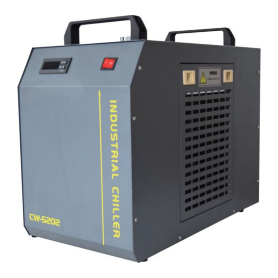
Page 5: Device Illustration
DEVICE ILLUSTRATION - 4 -... - Page 6 PROCEDURE Installing this industrial chiller is very simple. The first installation of a new machine can be carried out by following these steps: ①.OPEN THE PACKAGE TO CHECK IF THE MACHINE IS FIXED AND ALL NECESSARY ACCESSORIES ARE COMPLETE. ②.OPEN THE WATER SUPPLY INLET TO SUPPLY COOLING WATER (DON'T SPILL THE WATER OUT!).
-
Page 7: Parameter Adjustment
(3) The power supply is turned on, if the water temperature is lower than the set value, it is normal that the fan and other parts of the machine do not work. The temperature controller will automatically control the working state of compressor solenoid valves, fans and other components according to the set control parameters. -
Page 8: Display Panel And Buttons
except for factory parameter settings. DISPLAY PANEL AND BUTTONS (1) Display description: the data display area of the manual exercise board displays temperature, system parameters, alarm codes and other data; The blinking period for each field is 1 second; After powering on, the full display works normally after about 5 seconds. - Page 9 (3) Key definition description: KEYSTROKE NAME KEY FEATURES OK button to save and exit after RST key Determine the key setting data SET key Set the key Modify the parameter settings Numeric values/parameter entries are ▲key Dial up the key incremented Numeric value/parameter entry ▼key...
- Page 10 parameters. If no key is pressed within 20 seconds, the controller will automatically exit the parameter setting state and will not save the modified parameters. (When the parameter setting state, the system runs according to the original parameters) After holding the ▲▼ key at the same time, the thermostat is ▲+▼...
-
Page 11: Alarm Conditions
POWER-ON DISPLAY AND TEMPERATURE CORRECTION After power-on, the display panel should have 3 seconds flashing at the same time display indicator and digital tube (including D1, D2, — day. day), when the temperature value of the displayed room temperature and water temperature is different from the actual temperature, A4, A5 can be adjusted to correct the displayed temperature value. - Page 12 Concentrate: 1. E2 alarm is effective only after meeting the start-up alarm delay (A1) or entering the target temperature section (that is, between the set temperature and the set temperature + refrigeration return difference F2) after the thermostat is powered on 2.
-
Page 13: Menu Description
MENU DESCRIPTION DEFAULT CODE SET UP THE PROJECT RANGE REMARK VALUE Set the temperature 25.0 Smart temperature mode F9~F8/-20~ Thermostatic mode Temperature difference value -2.0 – 15~5 Refrigeration differential back Accuracy 0.1 degrees 0.1~3.0 Control mode 1 Smart, 0 Thermostat 0~1 Water temperature super 10.0... - Page 14 Traffic detection 1 input mode 00 = pulse amount 01 = 0~1 switching quantity Flow rate 1 factor 13.0 When set to 0 or 1 0.0~60.0 the coefficient has no effect Traffic detection 2 input mode 00 = pulse amount 01 = 0~1 switching quantity...
- Page 16 Technical Support and E-Warranty Certificate www.vevor.com/support...
Need help?
Do you have a question about the CW-5202 and is the answer not in the manual?
Questions and answers