Sign In
Upload
Download
Table of Contents
Contents
Add to my manuals
Delete from my manuals
Share
URL of this page:
HTML Link:
Bookmark this page
Add
Manual will be automatically added to "My Manuals"
Print this page
×
Bookmark added
×
Added to my manuals
Manuals
Brands
BSLBATT Manuals
Battery Pack
B-LFP48-52E
User manual
BSLBATT B-LFP48-52E User Manual
Rack battery pack
Hide thumbs
1
Table Of Contents
2
3
4
5
6
7
8
9
10
11
12
13
14
15
16
17
18
19
20
21
22
23
24
25
26
27
28
29
30
page
of
30
Go
/
30
Contents
Table of Contents
Bookmarks
Table of Contents
Table of Contents
Safety Precautions
Note before Installation
During Operation
System Application Introduction
PV Self-Use Surplus Power to Grid
Peak Shaving and Valley Filling
Standby Power Supply
Product Specification
Packing List
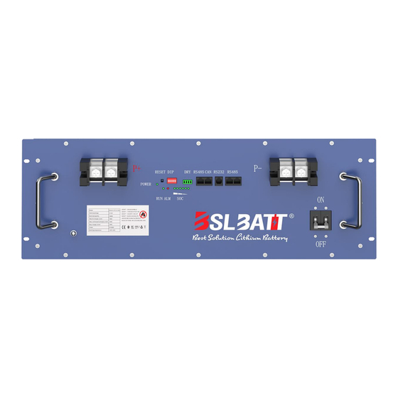
Battery Drawing
Interface Description
LED Display Definition
Battery Connection and Communication Instructions
Interface Diagram
Display Rendering
Battery Installation Instructions
Installation Location
Installation Tools
Installation Steps
Installing Battery Strings in Parallel
Appendix1
Appendix2
Appendix3
Advertisement
Quick Links
1
Battery Connection and Communication Instructions
Download this manual
Rack Battery Pack
User Manual
Product Name:
48V52/100/104/134/156/174/200/280/300Ah Battery
Model
No:
B-LFP48-52/100/104/134/156/174/200/280/300E
Version
No:
V2.4
Table of
Contents
Previous
Page
Next
Page
1
2
3
4
5
Advertisement
Table of Contents
Need help?
Do you have a question about the B-LFP48-52E and is the answer not in the manual?
Ask a question
Questions and answers
Related Manuals for BSLBATT B-LFP48-52E
Battery Pack BSLBATT B-LFP48-100E User Manual
(25 pages)
Battery Pack BSLBATT B-LFP12-100 User Manual
Lithium battery (10 pages)
Battery Pack BSLBATT B-LFP48-200E User Manual
Rack battery pack (30 pages)
Battery Pack BSLBATT B-LFP48-52PW User Manual
2.6/5/7/8/9/10/14/15kwh powerwall battery (27 pages)
Battery Pack BSLBATT Li-PRO Series User Manual
(26 pages)
Battery Pack BSLBATT ESS-GRID HV PACK Series User Manual
(60 pages)
Battery Pack BSLBATT ESS-GRID-P500E User Manual
Energy storage converter (100 pages)
Battery Pack BSLBATT PowerLine-5 Operating Instruction
Wall mounted lfp energy storage battery system (17 pages)
Battery Pack BSLBATT Powerline 5 Installation Manual
(23 pages)
Battery Pack BSLBATT MatchBox HVS Series Abridged User Manual
High voltage stacked battery system (51 pages)
Battery Pack BSLBATT PowerNest Series User Manual
Low voltage integrated ess (54 pages)
Battery Pack BSLBATT HV PACK 256/512V User Manual
Ups energy storage battery (10 pages)
This manual is also suitable for:
B-lfp48-100e
B-lfp48-104e
B-lfp48-134e
B-lfp48-156e
B-lfp48-174e
B-lfp48-200e
...
Show all
B-lfp48-280e
B-lfp48-300e
Table of Contents
Print
Rename the bookmark
Delete bookmark?
Delete from my manuals?
Login
Sign In
OR
Sign in with Facebook
Sign in with Google
Upload manual
Upload from disk
Upload from URL


Need help?
Do you have a question about the B-LFP48-52E and is the answer not in the manual?
Questions and answers