
Subscribe to Our Youtube Channel
Related Manuals for Wohler HDM Series


Summary of Contents for Wohler HDM Series
- Page 1 HDM Series • HDM-170-3G • HDM-215-3G Dual Input, LCD, Multi-Viewer Audio/ Video Monitors User Guide Part Number 821098, Revision A...
- Page 2 Wohler Technologies, Inc. reserves the right to change or improve our products at any time and without notice. In no event will Wohler Technologies, Inc. be liable for direct, indirect, special, incidental, or consequential damages resulting from any defect in the hardware, software, or its documentation, even if advised of the possibility of such damages.
-
Page 3: Table Of Contents
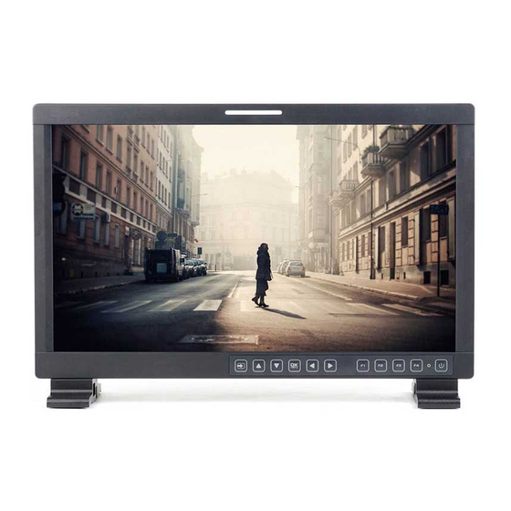
HDM Series Introduction Overview The HDM Series dual input, LCD video monitors are high- performance, professional LCD monitors that support advanced 10-bit digital processing technology with 3D comb filter and de-interlace, accurate scaling engine, GAMMA correction and color temperature adjustments to achieve the best possible image display. -
Page 4: Safety
Unplug the equipment during lightning storms or when unused for long periods of time. Use of a cart is neither recommended nor approved by Wohler. Refer all servicing to qualified service personnel. Servicing will be required under all of the following conditions: •... -
Page 5: Installation Recommendations
HDM Series I n s t a l la t io n R e c om m e n d a t io n s Safety Symbols WARNING: The symbol to the left warns of electric shock hazard inside the unit. -
Page 6: Unpacking And Installation
H D M Se r ie s U n p a ck in g a n d I n s t a ll a t io n Note: HDMI 1.3 or 1.4 cable lengths of 2m (6 feet) are guaranteed to work well. - Page 7 User guide CDROM • Warranty card Mounting The HDM Series monitors come standard with either a table top base (HDM-170-3G-TT and HDM-215-3G-TT) or rack ears (HDM-170-3G- RM). A standard VESA 100 pattern accomodates other user-supplied mountings, such as for walls.
- Page 8 H D M Se r ie s U n p a ck in g a n d I n s t a ll a t io n Place the monitor face down on a smooth surface and, as shown in Figure 1–1 on page 5, use a screwdriver and the supplied round head screws to fasten the bracket to the back of the monitor.
-
Page 9: Features
HDM Series F ea t u r e s Features The HDM Series monitors provide the following features: • 178° viewing angle • Multi-format analog and digital audio signals • Adjustment of the parameters for each channel • High-quality waveform or vector monitoring (as SUB input) •... -
Page 10: Front Panel Features
H D M Se r ie s F r o nt P a n el F e a t u r e s Front Panel Features The following feature descriptions refer to Figure 1–3 below. Figure 1–3 HDM Front Panel Status - Sub Status - Main LED Tally... - Page 11 HDM Series F r o n t P a n el F ea t u r e s • IMD: The 16 characters of the in-monitor display (IMD) can be displayed in red, green, yellow, or white. OSD CONFIG IMD , and define the static operation.
- Page 12 H D M Se r ie s F r o nt P a n el F e a t u r e s • Waveform/Vector: In PIP or PBP screen modes, the SUB window displays the waveform or vector, as defined in the Display Menu on page 20 Config Menu on page...
-
Page 13: Rear Panel Features
HDM Series R e a r P a n el F ea t u r e s Rear Panel Features Figure 1–5 HDM Complete Rear Panel Figure 1–6 HDM Rear Panel - Lower Right • (jack): Accepts power plug from the included 12 VDC DC IN power adapter. - Page 14 H D M Se r ie s Re a r Pa n e l F e a t u r es Figure 1–7 HDM Rear Panel - Upper Left (2 BNC) and (2 BNC): These inputs SDI Video Inputs SDI Outputs and outputs receive and regenerate the 3G/HD/SD-SDI signals.
- Page 15 HDM Series R e a r P a n el F ea t u r e s Figure 1–8 HDM Rear Panel - Lower Left • (2 BNC): CVBS composite analog video. Line 1 Input Output • (2 BNC) (2 BNC)
- Page 16 H D M Se r ie s Re a r Pa n e l F e a t u r es Table 1–1 GPI Pin Out Function GPI 1 GPI 2 GPI 3 GPI 4 GPI 5 GPI 6 Figure 1–9 RJ45 Connector Pin Map Table 1–2 RS485 Pin Out...
-
Page 17: Using The Menu System
U s i ng t h e M e n u S y s t e m Using the Menu System Configuring the HDM Series monitors is accomplished in the Menu . Each of the menus is explained on this and the following system pages. - Page 18 H D M Se r ie s U s in g t h e M en u S y s t e m Status Menu Note that none of the options displayed on the menu are STATUS editable. Table 1–3 Status Menu Default Parameters...
- Page 19 HDM Series U s i ng t h e M e n u S y s t e m Marker Menu Important: mode MARKER SCAN NATIVE is disabled when , or when the input signal is DVI or VGA. Table 1–5...
- Page 20 H D M Se r ie s U s in g t h e M en u S y s t e m Table 1–5 Marker Menu (Continued) Default Parameters Domain Range Value Sets the luminance (white level or brightness) to display safety, center, and area marker line, where: MARKER LEVEL •...
- Page 21 HDM Series U s i ng t h e M e n u S y s t e m Table 1–6 Audio Menu (Continued) Default Parameters Domain Range Value Select embedded audio for the right speaker/headphone/line output: SPEAK OUT R EBD CH1 •...
- Page 22 H D M Se r ie s U s in g t h e M en u S y s t e m Table 1–6 Audio Menu (Continued) Default Parameters Domain Range Value TOP (HORIZ) BOT (HORIZ) TOP LEFT (VERT) METER POSITION BOT LEFT BOT LEFT (VERT) BOT RIGHT (VERT)
- Page 23 HDM Series U s i ng t h e M e n u S y s t e m Table 1–7 Display Menu (Continued) Default Parameters Domain Range Value WAVE UNDER LIMIT • VITC • TIMECODE • D-VITC • Closed Caption Menu Table 1–8...
- Page 24 H D M Se r ie s U s in g t h e M en u S y s t e m Table 1–9 Config Menu (Continued) Default Parameters Domain Range Value • SMALL/LARGE PIP SIZE SMALL • TOP RIGHT •...
- Page 25 HDM Series U s i ng t h e M e n u S y s t e m Table 1–10 Color Temp Menu (Continued) Default Parameters Domain Range Value RED BIAS Presets Factory GREEN BIAS Calibrated BLUE BIAS When...
- Page 26 H D M Se r ie s U s in g t h e M en u S y s t e m Function Key Menu This menu lets you customize what you need each function key to do. Table 1–11 Function Key Menu Default Parameters...
- Page 27 HDM Series U s i ng t h e M e n u S y s t e m GPI Menu Table 1–12 GPI Menu Default Parameters Domain Range Value Select the function that each GPI will control. TALLY GPI 1 GREEN •...
- Page 28 H D M Se r ie s U s in g t h e M en u S y s t e m IMD Menu Table 1–13 IMD Menu Default Parameters Domain Range Value = Displays IMD DISPLAY = Does not display Select the color in which to display the IMD text: •...
- Page 29 HDM Series U s i ng t h e M e n u S y s t e m Table 1–13 IMD Menu Default Parameters Domain Range Value Select the communications baud rate: • 2400 • 4800 • 9600 9600 BAUD RATE •...
-
Page 30: Specifications
• = Inhibits all keys except KEY INHIBIT (to make POWER MENU setup changes) Specifications The general specifications of the HDM Series monitors are listed in Table 1–15 below. Table 1–15 HDM Specifications Specification HDM-170 HDM-215 12.5” H x 16.5” W x 14.6”... - Page 31 HDM Series S p e c if ic a t io n s Table 1–16 below lists the I/O specifications. Table 1–16 HDM Specifications Specification HDM Values • 6 BNCs: CVBS, S-Video, YPbPr, 3G/ HD/SD-SDI (supports embedded Video Inputs audio) •...
- Page 32 H D M Se r ie s Sp e ci fi ca t io n s Table 1–18 HDM CVBS I/O Specifications Specification HDM Values Differential Gain < 1% Differential Phase < 1.5° Table 1–19 below lists the specifications for SDI inputs. Table 1–19 HDM SDI Specifications Specification...
-
Page 33: Technical Function Overview
HDM Series T e ch n ic a l F u n ct io n O v e rv ie w Technical Function Overview Figure 1–10 below illustrates the overall functionality of the HDM Series monitors. Figure 1–10 HDM Block Diagram...
Need help?
Do you have a question about the HDM Series and is the answer not in the manual?
Questions and answers