Table of Contents
Advertisement
Quick Links
Download this manual
See also:
User Manual
Advertisement
Table of Contents

Related Manuals for Wohler AMP1-S8DA


Summary of Contents for Wohler AMP1-S8DA
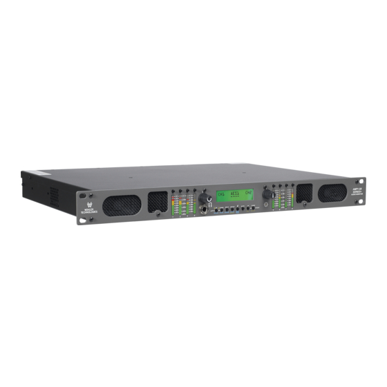
- Page 1 AMPx-S8 Series • AMP1-S8DA • AMP1-S8MDA-3G • AMP2-S8DA • AMP2-S8MDA-3G 8-Channel, Multi-Format, Analog/Digital Audio Monitors User Guide Part Number 821030, Revision E...
-
Page 2: Customer Support
Wohler Technologies, Inc. reserves the right to change or improve our products at any time and without notice. In no event will Wohler Technologies, Inc. be liable for direct, indirect, special, incidental, or consequential damages resulting from any defect in the hardware, software, or its documentation, even if advised of the possibility of such damages. -
Page 3: Table Of Contents
Table of Contents Preface ........vii Introduction .............. - Page 4 Installation ..............6 Intial Setup.............. 6 Power Up..............6 Chapter 2. System Overview ..... . . 7 Introduction..............7 Overview ..............7 Topics ..............
- Page 5 Analog Output Preference..........24 Monitoring and Mixing Modes .......... 25 Arbtrary Mixing ............25 Single ..............26 Pairs ..............26 Downmix..............27 Muting the Speakers ............29 Phase Correlation ............30 SDI Inputs ..............31 Selecting SDI Groups and Subgroups ......31 Configuring for SDI Delay ........
- Page 6 Chapter 5. Setup Menu ......43 Introduction..............43 Overview ..............43 Topics ..............43 Accessing Setup Mode............44 Analog Output Preference Mode........46 Recalling a Preset ............46 Saving a Preset .............47...
-
Page 7: Preface
Preface Introduction Overview The preface lists the new features and functionality for this release. Topics Topics Page What’s New viii Functionality Enhancements viii 8 2 1 0 3 0 : A M P x-S8 S e r i e s Us e r G u i d e ©... -
Page 8: What's New
Moreover, we are replacing some similar products as well that may also include other changes. New Version Replacement Old Version Suggestions AMP1-S8DA (PN 8101-0030) AMP1-S8DA (PN 8101-0110) AMP2-S8DA (PN 8103-0020) AMP2-S8DA (PN 8102-0060) Software Termination In this release, all terminations are no longer on the rear panel; they are now controlled by the software. -
Page 9: Rear Panel Connector Arrangements
Preface F u n c t i o n a l i t y E n h a n c e m e n t s Rear Panel Connector Arrangements Note that in the process of redesigning the AMPx-S8 Series monitors, we have rearranged the rear panels. -
Page 11: Chapter 1. Installation
CHAPTER 1 Installation Introduction Overview This chapter describes the front panel controls and the rear panel connectors in detail. It also describes how to use the front panel user interface for data display and system configuration. Configuration procedures are covered in detail in Chapter 3 on page Topics Topics... -
Page 12: Unpacking
Unpack the AMPx-S8 Series monitor and inspect for any apparent physical damage that may have occurred in transit. If the unit has been damaged, contact Wohler customer support for assistance. (Wohler’s contact information is on page ii of this document.) In addition to the monitor, the package should contain: •... -
Page 13: Safety Symbols
Unplug the equipment during lightning storms or when unused for long periods of time. Use of a cart is neither recommended nor approved by Wohler. Refer all servicing to qualified service personnel. Servicing will be required under all of the following conditions: •... -
Page 14: Installation Recommendations
C h a p t e r 1 I n st a l la t i o n I n s t a ll a t io n R e c o m m e n d a t i o n s instruction manual, may cause harmful interference to radio communications. -
Page 15: Mechanical Bracing
C h a p t e r 1 Installation I n s ta l la t i o n R e c o m me n d a t io n s use of thin card stock and/or felt or foam weather-stripping type materials between adjacent vibrating surfaces, or tying up loose cables, etc., may be required to stop vibrations external to the unit. -
Page 16: Power
C h a p t e r 1 I n st a l la t i o n I n s t a l l a t io n Power The unit comes with a standard 24VDC/3.0 A internal power supply and connects an A/C mains power source (65W, 100 to 240 VAC, 50/ 60Hz) through the IEC connector provided on the rear panel of the unit. -
Page 17: Chapter 2. System Overview
CHAPTER 2 System Overview Introduction Overview This chapter describes how to install the AMPx-S8 Series monitor into a standard 19”-rack and how to connect the audio cables. Topics Topics Page Introduction Front Panel Controls Rear Panel Connectors Monitoring Inputs Channel Selection and Mixing 8 2 1 0 3 0 : A M P x-S8 S e r i e s Us e r G u i d e ©... -
Page 18: Front Panel Controls
C h a p t e r 2 S y s te m O v e rv i e w F r o n t P a n e l C o n t r o l s Front Panel Controls Features and Simple Controls Refer to the images in Figure 2–1... - Page 19 C h a p t e r 2 System Overview F r o n t P a n e l C o n t r o l s Figure 2–1 The AMP1-S8 Series Front Panel Brightness Speaker Assign/ Presets Volume Headphones LCD Screen Balance...
-
Page 20: Lcd Screen
C h a p t e r 2 S y s te m O v e rv i e w F r o n t P a n e l C o n t r o l s • Level Meter Brightness (Potentiometers, Left and Right): Use a small slot screwdriver to adjust the brightness of the bar graph meters using these two recessed trim pot controls. -
Page 21: User Interface
C h a p t e r 2 System Overview F r o n t P a n e l C o n t r o l s then they will display as short dashes. Each dash (-) indicates a position for displaying the channel pairs available for monitoring from left to right: 1/2, 3/4, 5/6 and 7/8. -
Page 22: Menu Navigation
C h a p t e r 2 S y s te m O v e rv i e w F r o n t P a n e l C o n t r o l s Table 2–1 White Control Functionality (Continued) Button Setup Mode... -
Page 23: Rear Panel Connectors
Note: The pin-out for this connector is compatible with Tascam DB-25 to XLR cable assemblies. Contact your Wohler sales representative for availability. (Wohler’s contact information is on page ii of this document.) 8 2 1 0 3 0 : A M P x-S 8 S e r i e s U s e r G u i d e... - Page 24 C h a p t e r 2 System Overview R e a r P a n e l C o n n e c t o r s Figure 2–5 The AMP1-S8MDA-3G Rear Panel Standard Unbalanced AES Out (HD-15) can be replaced with Balanced AES Out from SDI (DB-25) shown.
-
Page 25: Output Connectors
C h a p t e r 2 System Overview R e a r P a n e l C o n n e c t o r s Figure 2–7 AES/PCM Input and Loop-Through DB-25 Pin-Out • 3G/HD/SD-SDI In (1 and 2, BNC-F): These inputs accept SDI video signals for the 3G models. - Page 26 The pin-out for this connector is compatible with Tascam DB-25 to XLR cable assemblies. Contact your Wohler sales representative for availability. (Wohler’s contact information is on page ii of this document.). 8 2 1 0 3 0 : A M P x-S8 S e r i e s U se r G u i d e ©...
- Page 27 C h a p t e r 2 System Overview R e a r P a n e l C o n n e c t o r s Figure 2–9 AES Balanced Out from SDI DB-25 Pin-Out • Selected Downmix/Analog Out (Left and Right, XLR-M): These connectors are balanced analog outputs of the speaker assign (or downmix) source as selected for the left and right speaker channels.
-
Page 28: Programming And Remote Access Connectors
(Status 1 through 4). Note: For more complete information about the functionality of Remote connector, contact your Wohler technical support representative and ask for the documents with part numbers 824016 and 824017. 8 2 1 0 3 0 : A M P x-S8 S e r i e s U se r G u i d e... -
Page 29: Rotary Switch Connectors
C h a p t e r 2 System Overview R e a r P a n e l C o n n e c t o r s Rotary Switch Connectors • OPT 2 (10-Position Rotary Switch): This recessed 10-position rotary switch allows for standard operation and software upgrades. -
Page 30: Monitoring Inputs
C h a p t e r 2 S y s te m O v e rv i e w M o n it o r in g I n p u ts Table 2–7 Reference Setting Values and Definitions Reference Level Function Position Analog (dBu) -
Page 31: Monitoring An Aes Input
C h a p t e r 2 System Overview M o n i t o r i n g I n p u t s Continue on to Channel Selection and Mixing on page Monitoring an AES Input To monitor an AES signal, do one or both of the following: •... -
Page 32: Channel Selection And Mixing
C h a p t e r 2 S y s te m O v e rv i e w C h a n n e l S e l e c t i o n a n d M i x i n g Continue on to Channel Selection and Mixing immediately below. -
Page 33: Chapter 3. Audio Configuration
CHAPTER 3 Audio Configuration Introduction Overview This chapter is the “how to” chapter. All topics listed below are sorted alphabetically for easy reference. For information about presets refer to Chapter Presets on page Topics Topics Page Introduction Analog Output Preference Monitoring and Mixing Modes Muting the Speakers Phase Correlation... -
Page 34: Analog Output Preference
C h a p t e r 3 A u d i o C o n f i g u r a ti o n A n a l o g O u t p u t P re f e re n c e Analog Output Preference The Analog Output Preference determines how the Selected/... -
Page 35: Monitoring And Mixing Modes
C h a p t e r 3 Audio Configuration M o n i t o r i n g a n d M i x i n g M o d e s Press either the Down arrow followed by the Enter button to change the setting, or press the... -
Page 36: Single
C h a p t e r 3 A u d i o C o n f i g u r a ti o n M o n it o r in g a n d M ix in g M o d e s Single This mode allows you to select one and only one signal for each speaker independently of the other speaker and is most useful when you are... -
Page 37: Downmix
C h a p t e r 3 Audio Configuration M o n i t o r i n g a n d M i x i n g M o d e s Downmix This mode is most useful when multiple signals need to be mixed together and monitored at the same time. - Page 38 C h a p t e r 3 A u d i o C o n f i g u r a ti o n M o n it o r in g a n d M ix in g M o d e s Figure 3–7 DM1 Mix Diagram •...
-
Page 39: Muting The Speakers
C h a p t e r 3 Audio Configuration M u t in g t h e S p e a k e r s • DM3: This downmix is the same as DM1 except that the surround level is fixed at –3 dB. DM3 is equivalent to the Japanese ARIB Set 3 downmix formula. -
Page 40: Phase Correlation
C h a p t e r 3 A u d i o C o n f i g u r a ti o n P h a s e C o r r e l a t i o n Pressing the Mute button allows you to step through three mute... -
Page 41: Sdi Inputs
C h a p t e r 3 Audio Configuration S D I I n p u t s With typical stereo program material, the moving block display is normal. If the signals to the speakers are completely independent, they will have a correlation result of 0, and the block will be stationary in the center of the screen. -
Page 42: Configuring For Sdi Delay
C h a p t e r 3 A u d i o C o n f i g u r a ti o n S D I I n p u t s Table 3–3 SDI Group Select Button Left Bar Graph Bank Right Bar Graph Bank Press... -
Page 43: Selecting The Input Signal
C h a p t e r 3 Audio Configuration S e l e c t in g t h e I n p u t S ig n al Figure 3–12 SDI Delay Setting -Setup- SDI Delay: 140 ms Press either the Down buttons to select the delay in... -
Page 44: Setting The Monitor's Startup Configuration
C h a p t e r 3 A u d i o C o n f i g u r a ti o n S e t ti n g t h e M o n it o r ’s S ta r tu p C o n f ig u ra t io n Setting the Monitor’s Startup Configuration You can configure the AMPx-S8 Series monitor to start up from a... -
Page 45: Terminating/Unterminating Inputs
C h a p t e r 3 Audio Configuration T e r m i n a t i n g / U n t e r m i n a t i n g I n p u t s Terminating/Unterminating Inputs Each of the AES and bitstream inputs on the AMPx-S8 may be terminated or unterminated independently of each other. - Page 46 C h a p t e r 3 A u d i o C o n f i g u r a ti o n T e r m in a ti n g / U n te r m i n a t in g I n p u ts Press the or the Down...
-
Page 47: Chapter 4. Presets
CHAPTER 4 Presets Introduction Overview This chapter describes how to create, recall, modify, and erase presets. It also discusses using Preset mode for fast system configuration. Topics Topics Page Introduction What are Presets? Methods of Accessing the Presets 8 2 1 0 3 0 : A M P x-S8 S e r i e s Us e r G u i d e ©... -
Page 48: What Are Presets
C h a p t e r 4 P re s e t s W h a t a r e P r e s e t s ? What are Presets? The AMP1-E8 is an incredibly flexible tool for monitoring multiple audio streams. -
Page 49: Enabling/Disabling Preset Mode
C h a p t e r 4 Presets M e t h o d s o f A c c e s s i n g t h e P r e s e t s Note: When this mode is enabled, you can no longer directly select the inputs by the input type (e.g., AES 1, SDI 2, analog, and so on). -
Page 50: Saving A Preset
C h a p t e r 4 P re s e t s M e th o d s o f Ac c e s s i n g th e P r e s e ts Saving a Preset Press Fn+Preset 1 If Preset 1 is currently empty, the system will prompt you to save... - Page 51 C h a p t e r 4 Presets M e t h o d s o f A c c e s s i n g t h e P r e s e t s Name the preset by using the Down arrow buttons to scroll through the available list of characters.
-
Page 53: Chapter 5. Setup Menu
CHAPTER 5 Setup Menu Introduction Overview This chapter explains the options in the Setup menu. Figure 5–1 on page provides a structural overview. Topics Topics Page Introduction Accessing Setup Mode Analog Output Preference Mode Recalling a Preset Saving a Preset Preset Mode Erasing a Preset SDI Delay... -
Page 54: Accessing Setup Mode
C h a p t e r 5 S e t u p M e n u A c c e s s i n g S e t u p M o d e Accessing Setup Mode Figure 5–1 Setup Menu Tree Normal Enter/Esc... - Page 55 C h a p t e r 5 Setup Menu A c c e s s i n g S e t u p M o d e Enable Setup mode by pressing and holding the button and then pressing the button.
-
Page 56: Analog Output Preference Mode
C h a p t e r 5 S e t u p M e n u A n a l o g O u t p u t P re f e re n c e M o d e To exit Setup Mode , press the... -
Page 57: Saving A Preset
C h a p t e r 5 Setup Menu S a v i n g a P r e s e t Figure 5–2 Recalling an Existing Preset Choose PresetNum Preset1: Off Air Press the Down buttons to scroll through the presets. In the example above (Figure 5–2), Preset 1 is called... -
Page 58: Creating A New Preset
C h a p t e r 5 S e t u p M e n u S a v in g a P r e s e t Creating a New Preset Note: To cancel the procedure at any time during this process, press the Escape button and the preset will not be saved... -
Page 59: Overwriting An Existing Preset
C h a p t e r 5 Setup Menu S a v i n g a P r e s e t Naming will automatically end after you select eight characters, or when you press the button when appears on the Enter _DONE_ display. - Page 60 C h a p t e r 5 S e t u p M e n u S a v in g a P r e s e t Pressing the Enter button keeps the old name for the new preset and returns the unit to normal operation.
-
Page 61: Preset Mode
C h a p t e r 5 Setup Menu P r e s e t M o d e Preset Mode For more information about presets Refer to Chapter Setup Menu on page To enable or disable Preset mode: Press Fn+Setup Use the... -
Page 62: Sdi Delay
Figure 5–11 Erasing a Preset - Confirmation Erase Preset? Preset1: Off Air Pressing the Enter button will erase that preset. Pressing the button will not erase that preset. In either case, control returns to the menu to choose another preset to erase. Figure 5–12 Erasing a Preset - Select the Preset to Erase... -
Page 63: Startup
C h a p t e r 5 Setup Menu S t a r t u p Startup entry within the Setup Menu determines the input used Startup by the unit at power up. When set to Used, the unit will power Last up the same way that the unit was before power was interrupted. -
Page 64: Bitstream Detection
Bitstream Detection The unit will now mute an input pair if it detects the presence of a non- PCM stream (such as a Dolby or DTS bitstream) on that pair. The unit detects bitstreams with two methods: Preamble detection Not-Audio AES Channel status flag is asserted In terms of Method A, encoded bitstreams contain key data sequences that identify the type of encoding used. -
Page 65: Phase Bits
C h a p t e r 5 Setup Menu P h as e B i t s Phase Bits For units with SDI de-embedder cards installed, there is a new menu item available, entitled Phase Bts, which stands for phase bits. These are bits that are embedded in SDI streams that allow the audio sample rate to be independent of the video pixel clock, and they are required by the latest SMPTE standards. - Page 66 C h a p t e r 5 S e t u p M e n u P h a s e B it s 8 2 1 0 3 0 : A M P x-S8 S e r i e s U se r G u i d e ©...
-
Page 67: Chapter 6. Features And Specifications
CHAPTER 6 Features and Specifications Introduction Overview This chapter details the features of each of the monitors in the series and provides the technical specifications. It also outlines the distinctions between models. Topics Topics Page Introduction Features Specifications Technical Functional Overview 8 2 1 0 3 0 : A M P x-S8 S e r i e s Us e r G u i d e ©... -
Page 68: Features
C h a p t e r 6 F e a t u r e s a n d S p e c i fi c a ti o n s F e a t u r e s Features Common Features The AMPx-S8 Series audio monitors provide a complete, exceptionally high-quality 3G/HD/SD-SDI, PCM and analog stereo audio... -
Page 69: Specifications
C h a p t e r 6 Features and Specifications S p e ci f i c a t i o n s Specifications Table 6–2 Specifications for the AMPx-S8 Series Monitors Specification Value Power Consumption 72 W max AC Mains Input 100 to 240 VAC, 50 to 60 Hz Analog Input Impedance... -
Page 70: Technical Functional Overview
• AES Bal In/Loop Out (DB-25) Other level meter scales are available at time of manufacture including BBC, DIN, and others. Contact Wohler for more information concerning alternate scales. Note: All features and specifications are subject to improvement without notice. - Page 71 C h a p te r 6 Features and Specifications T e c h n i c al F u n c ti o n al O v e r v ie w Figure 6–1 AMP1-S8DA Block Diagram LCD Display Group & Channel Switching Status 53-Segment RS-232 A uP Control / U.I.
- Page 72 C h a p t e r 6 Features and Specifications T e c h n i c a l F u n c t i o n a l O v e r v i e w Figure 6–2 AMP2-S8DA Block Diagram LCD Display Group &...
- Page 73 C h a p te r 6 Features and Specifications T e c h n i c al F u n c ti o n al O v e r v ie w Figure 6–3 AMP1-S8MDA-3G Block Diagram LCD Display Group &...
- Page 74 C h a p t e r 6 Features and Specifications T e c h n i c a l F u n c t i o n a l O v e r v i e w Figure 6–4 AMP2-S8MDA-3G Block Diagram LCD Display Group &...
Need help?
Do you have a question about the AMP1-S8DA and is the answer not in the manual?
Questions and answers